 English




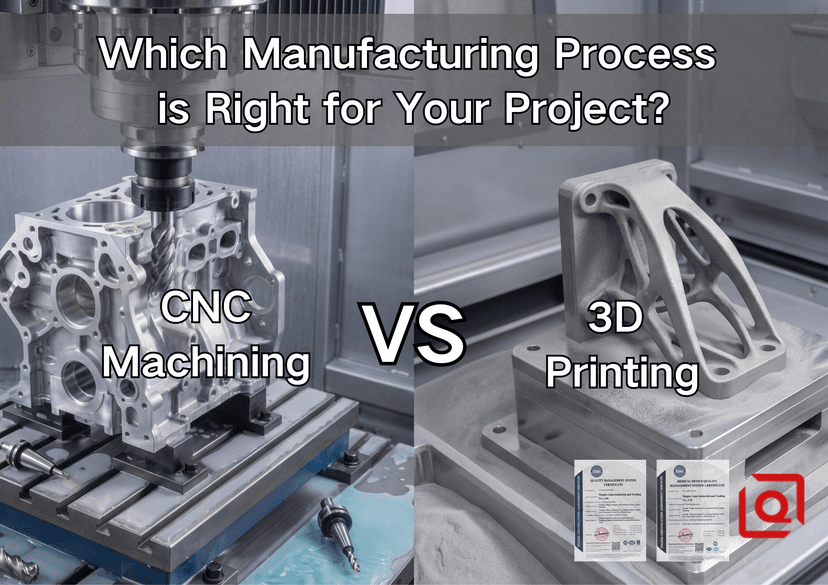
Last Tuesday, we scrapped a $3,400 batch of 7075-T6 aircraft brackets because a design team spec’d LPBF 3D printing for a high-fatigue hinge boss with a 0.8 µm Ra surface requirement without accounting for micro-porosity nucleation under 180 MPa cyclic shear. Stop defaulting to metal additive just because the CAD looks clean on a 4K monitor. When your thermal stress relief cycle in a vacuum furnace slumps a 0.4 mm cantilever overhang, or when your 5-axis G-code chatters across an unsupported rib wall at 12,000 RPM, the boundary between subtractive chip-making (DIN 8589) and powder bed fusion (ASTM F3055) stops being an academic debate and becomes a scrap bin full of oxidized titanium and spent carbide end mills.
1. Physics at the Interface: Material Integrity & Microstructure
Let's talk density and grain direction. You cannot dodge anisotropy.
In 5-axis CNC milling, you carve into wrought, extruded, or forged billet stock—materials like Alcoa Alca 5-7050 or wrought 316L (ASTM A276). Grain boundaries are continuous and aligned through previous thermo-mechanical rolling. When taking a 4 mm radial depth of cut(ap) with a 12 mm solid carbide 4-flute end mill at 450 m/min surface speed (Vc) and 0.08 mm/tooth feed (fz) under 70 bar high-pressure through-spindle coolant, the material's yield strength (Rp0.2) remains homogenous across X, Y, and Z axes. Yield stays at a rock-solid 505 MPa for 7075-T6.
Shop-Floor Warning: Moisture & Porosity Nucleation
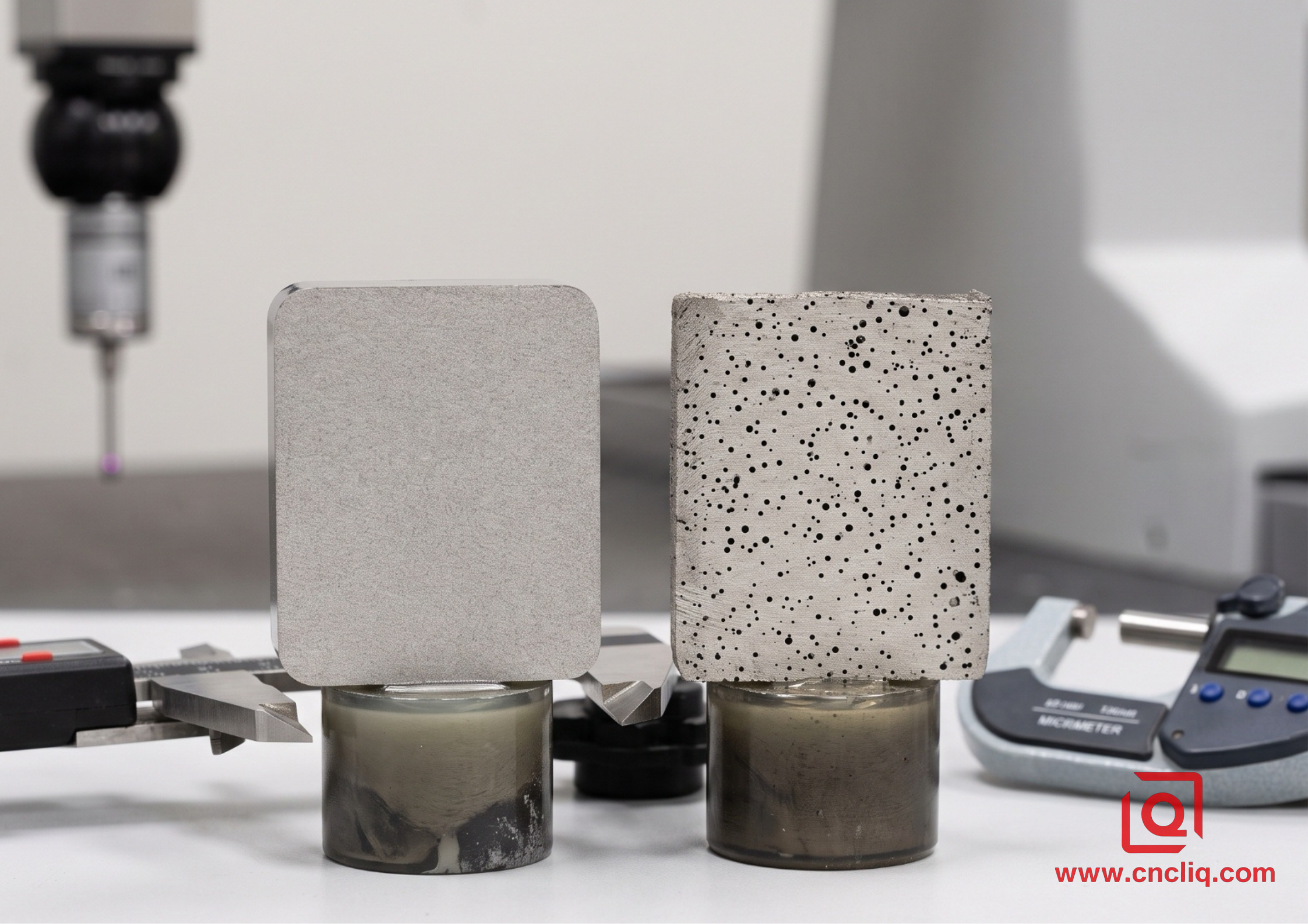
Switch over to Laser Powder Bed Fusion (LPBF) with Scalmalloy or Ti-6Al-4V Grade 23 powder (15–45 µm particle size distribution). If your virgin powder sits in an unsealed hopper at 65% relative humidity for over 3.5 hours, moisture pickup jumps from 0.02% to 0.14% by weight. During the 400W Yb-fiber laser scan pass (hatch distance 105 µm, layer thickness 30 µm, scan speed 1200 mm/s), trapped hydrogen gas expands within the molten pool. The result? Sub-surface spherical gas pores (20 to 85 µm diameter) that act as stress concentration risers, dropping your fatigue limit (N=10^7 cycles) from 510 MPa down to 290 MPa. You won't see this on your 3D CAD model, but your CMM and ultrasonic NDT inspector sure will.
2. Geometry, Tolerancing, and Surface Metrology
Tight tolerances are where budgets go to die. Know your numbers before sending STEP files.
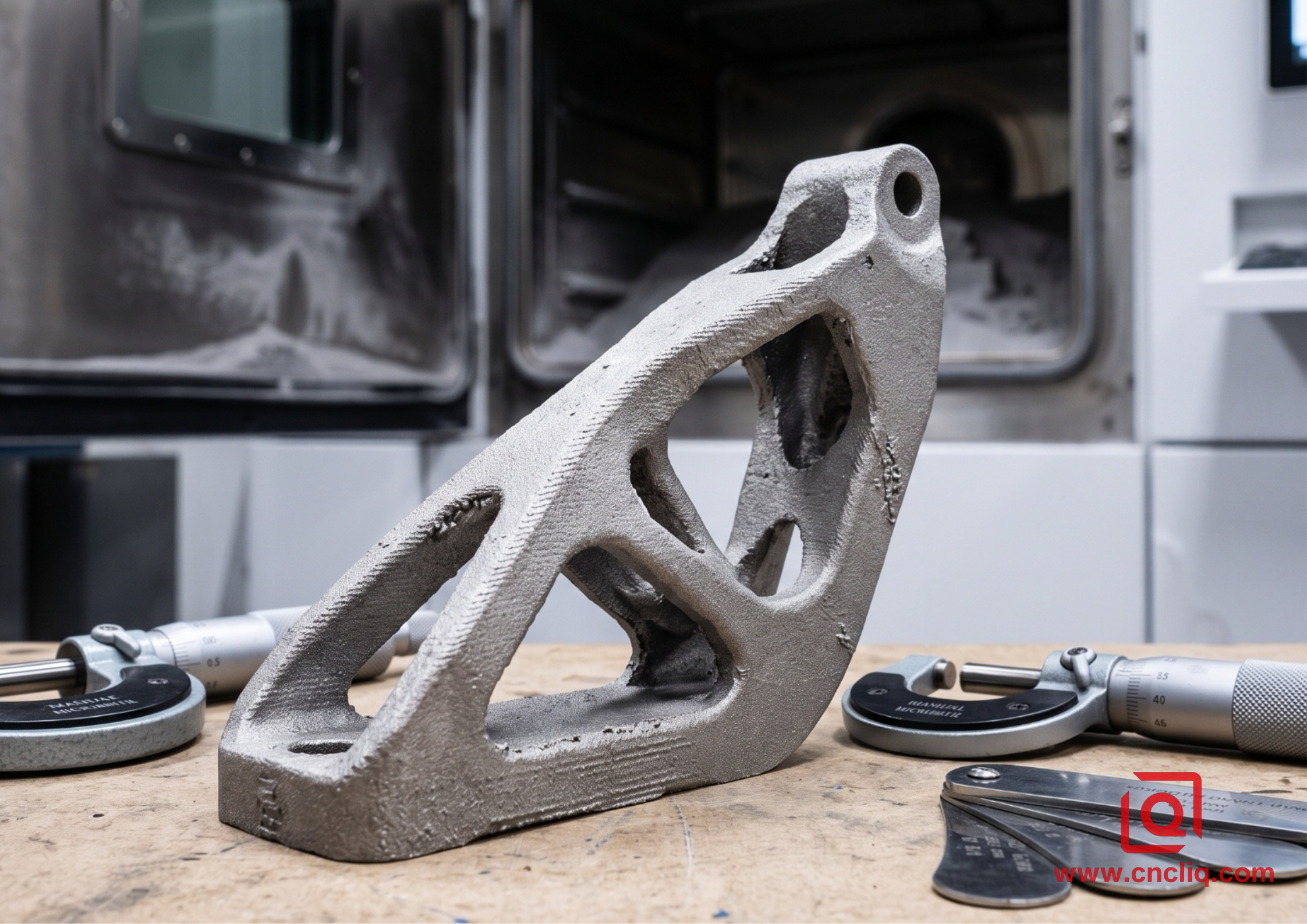
If your print calls for ISO 2768-m (Fine) with an H7 bore tolerance (+0.012/-0.000 mm on a Ø20 mm reamed hole), stop thinking about raw 3D printing immediately. LPBF thermal gradient mechanism (TGM) creates residual stress profiles up to 450 MPa in 17-4PH stainless steel. As the build platform lowers into the powder vat, unsupported geometries shrink unevenly. You get a stair-stepping effect with an arithmetic mean roughness (Ra) ranging from 8.5 µm to 15.2 µm. That requires downstream post-processing: wire EDM cutoff, heat treatment (H900 condition at 480°C for 1 hour), shot peening with Zirblast ceramic beads at 0.35 MPa, and secondary CNC milling or CNC cylindrical grinding to hit final drawing specs.
| Engineering Metric | 5-Axis CNC Milling / Turning | LPBF Metal 3D Printing | FDM / SLA Polymers |
| Standard Tolerances | ±0.005 mm to ±0.025 mm (ISO 2768-f) | ±0.100 mm to ±0.250 mm (ISO 2859) | ±0.15 mm (FDM) / ±0.05 mm (SLA) |
| As-Built Surface Roughness ($R_a$) | 0.4 µm – 1.6 µm (ASME B46.1) | 8.0 µm – 18.0 µm (as-printed) | 6.3 µm – 12.5 µm (layer-dependent) |
| Isotropic Mechanical Strength | 100% (Fully Isotropic) | 85%–92% Z-axis debit (Anisotropic) | 60%–75% Layer shear weakness |
| Min Wall Thickness | 0.5 mm (requires rigid fixturing) | 0.3 mm (self-supporting angles >45°) | 0.8 mm (FDM nozzle bound) |
| Machine Setup / Changeover Time | 1.5 to 4.0 Hours (CAM, Vise, G54) | 3.0 to 6.0 Hours (Sieving, Inert gas, leveling) | 0.2 to 0.5 Hours |
3. The Real-World Workflow: Step-by-Step Production Execution
A. CNC Machining Operational Sequence (Target: High-Precision 6061-T6 Manifold)
-
Raw Material Prep: Saw cut 6061-T6 extruded bar stock to 125×85×65mm. Face datum A on 3-axis VMC using a 50 mm indexable face mill with SEKT1204 inserts (n=4500RPM, f=1200mm/min).
-
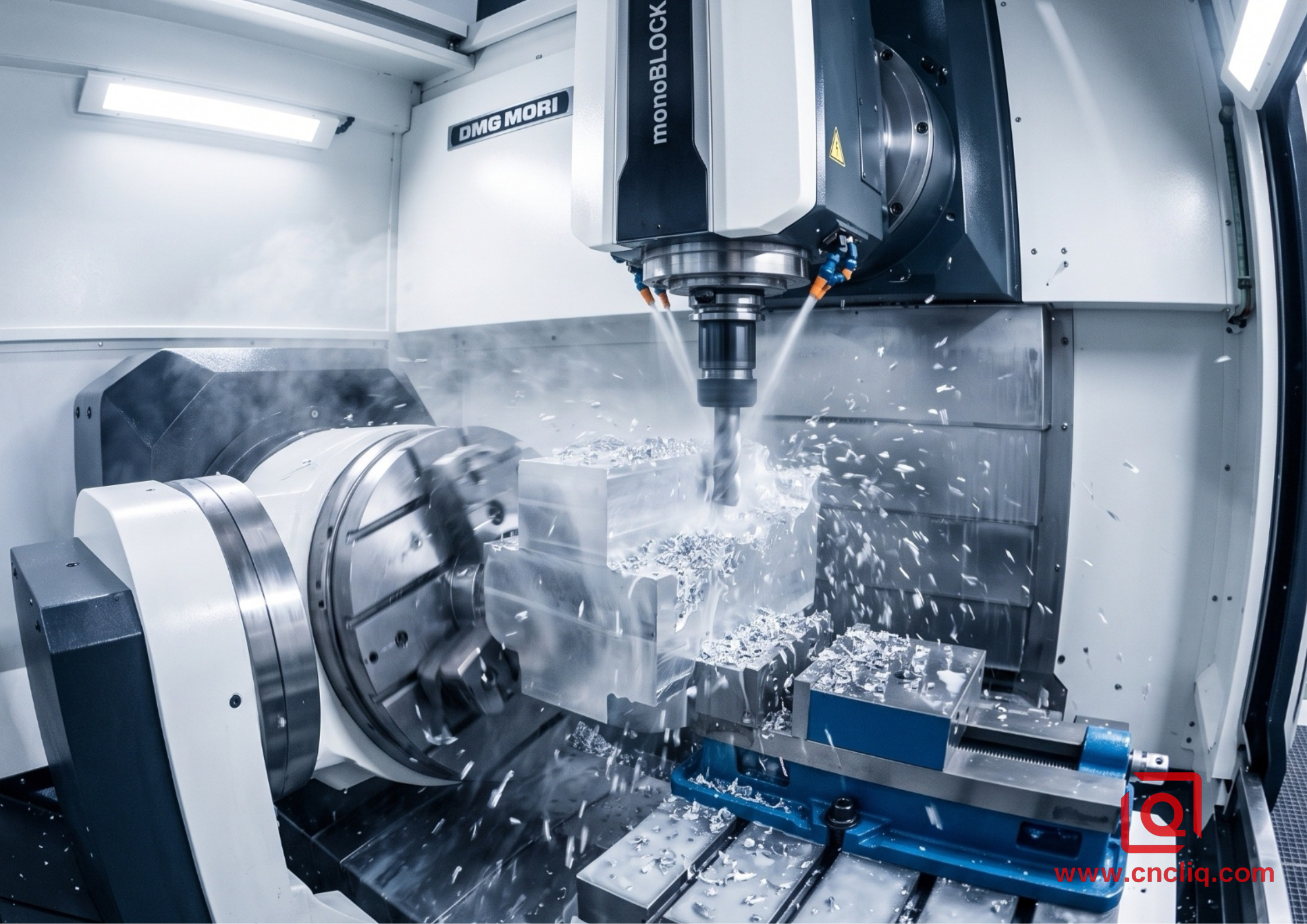
First Operation (Op 10): Clamp in soft jaws at 25 Nm torque. Rough pocketing with 10 mm carbide roughing end mill (3-flute, variable helix 37°/38°), trochoidal toolpath engagement (ae =1.5mm, ap =18mm. feed speed 3200mm/min).
-
Semi-Finishing & Boring: Bore valve cavities using precision micro-boring head to Ø22.008 mm (+0.005/-0.000 mm). Spray water-soluble synthetic coolant (8% concentration, pH 9.1).
-
Op 20 Flip & Deburr: Flip part to G55 offset, machine locating faces, chamfer edges with 90° carbide chamfer mill at 0.3mm×45°. Manual thermal deburring or high-pressure waterjet flush to clear internal chips.
B. LPBF Metal Additive Operational Sequence (Target: Lightweight Ti-6Al-4V Bracket)
-
Slicing & Support Generation: Import STEP into Materialise Magics. Set layer thickness to 30 µm. Apply block support structures to overhangs below 42° inclination. Export CLI build file.
-
Atmospheric Preparation: Purge EOS M 290 build chamber with Argon gas (99.999% purity) until O₂ concentration drops below 100 ppm (0.01%) to prevent titanium hydride embrittlement. Preheat build plate to 160°C.
-
Laser Sintering Process: Execute 14-hour print run (280W laser power, 1050 mm/s scan speed). Monitor melt-pool pyrometry in real-time for thermal hot-spots.
-
Post-Processing & EDM Wire Cut: Vacuum stress relief anneal at 730°C for 2 hours in Argon inert furnace. Wire EDM cutoff from build plate using 0.25 mm brass wire (pulse time 12 µs). Remove tree supports with pneumatic carbide rotary burr. Grit blast with Al₂O₃(120 mesh) at 0.4 MPa.
4. Total Cost Breakdown & Economic Breakeven Curve
Don't fall for "tooling-free means cheaper."
For a batch size of 1 to 15 parts with highly complex organic conformal cooling channels, LPBF 3D printing wins because zero custom workholding is required. Machine hourly rates for an EOS M 290 or TruPrint 3000 sit around $75–$120/hr, plus raw Ti-6Al-4V powder costs at $220/kg. However, as quantity scales to 100–500 units, CNC machining economics drastically pull ahead. A dual-pallet 5-axis machining center running a multi-cavity tombstone fixture drops cycle time per part from 6.5 hours (LPBF layer deposition) to 11.5 minutes (subtractive milling). Setup cost ($300 CAM programming + $400 custom fixture plate) amortizes to under $1.40 per part over 500 units.
5. DFM Golden Rules: Making the Final Engineering Call
-
Pick CNC Machining when: You need certified wrought material properties (ASTM/AMS specs), tight dimensional tolerances (<±0.01mm, Ra<0.8µm surface finish without manual grinding, or production runs exceeding 50 parts where per-unit cost must drop exponentially.
-
Pick Metal 3D Printing (LPBF/DMLS) when: You are producing topological-optimized structural parts with internal lattice infill, internal curved fluid channels that a deep-hole drill cannot physically reach, or urgent aerospace prototypes where weight reduction saves more money over the component lifespan than the upfront additive manufacturing cost.
FAQs
Q1: Can 3D printed metal parts achieve the same dimensional tolerances as 5-axis CNC machined components?
A: No, not as-printed. LPBF metal 3D printing yields as-built tolerances around ±0.100mm to ±0.250mm due to localized thermal gradients and powder sintering limits. To achieve tight fits like ISO H7/g6 or tolerances under ±0.010mm, the part must undergo post-process CNC milling, micro-boring, or cylindrical grinding on oversized critical features.
Q2: How does surface roughness (Ra) compare between raw LPBF prints and CNC milled parts?
A: As-printed LPBF titanium or stainless steel typically exhibits Ra between 8.0µm and 18.0µm due to partially fused powder particles. In contrast, standard 5-axis CNC milling routinely achieves 0.8µm to 1.6µm Ra out of the machine. Achieving Ra<0.8µm on 3D printed parts requires multi-stage media blasting, abrasive flow machining, or CNC secondary finishing.
Q3: Is metal 3D printing always more expensive than CNC machining for low-volume production?
A: Not for highly complex geometry. For 1 to 5 units of topological-optimized aerospace brackets or parts with internal conformal cooling channels, LPBF is often cheaper because it avoids $500–$2,000+ in custom 5-axis workholding fixtures and complex CAM multi-axis programming. However, once quantities exceed 20–50 units, CNC machining's short cycle time quickly undercuts additive costs.
Q4: Can we directly machine LPBF 3D printed metal parts without heat treatment?
A: We strongly advise against it. Rapid laser quenching creates massive internal residual stresses (up to 450MPa in 17-4PH or Inconel 718). Machining an as-printed part releases these stresses, causing immediate dimensional warping, tool chatter, or catastrophic stress-corrosion cracking. Always run a vacuum stress-relief anneal cycle before wire EDM cutoff or CNC finishing.
Q5: What file formats are required for DFM analysis?
A: STEP (.stp) or IGES (.igs) native 3D CAD files are required for both CNC toolpath simulation and LPBF layer slicing. For CNC, please include 2D PDF drawings detailing critical GD&T, thread pitch specs, and tolerance callouts.
Summary
Deciding between 5-axis CNC machining and LPBF metal 3D printing comes down to a strict engineering trade-off: geometry vs. structural integrity. LPBF excels at complex, topologically optimized geometries and internal channels, but suffers from anisotropic strength, micro-porosity risks, and rough as-printed finishes (Ra 8.0–18.0μm). CNC machining guarantees fully isotropic wrought mechanical properties, tight tolerances (±0.005mm), and unbeatable unit cost efficiency for production runs above 50 parts. Always evaluate load conditions, GD&T requirements, and production volume before freezing your CAD files.
Need Engineering Validation for Your Component Drawings?
Our engineering team performs full DFM audits, G-code simulations, and finite element stress analysis for both 5-axis CNC machining and metal additive manufacturing. Send your STEP/IGES CAD files today for a detailed manufacturing feasibility report and instant line-item quotation.
Contact Information
Disclaimer
The technical data and process parameters presented here are for reference only and do not constitute a binding guarantee. Actual tolerances, material properties, and surface finishes depend on specific part geometry, equipment setup, and post-processing. Buyers are responsible for verifying drawing requirements and engineering specs before placing orders.
Liqin Manufacturing Team
We are Ningbo Liqin Industrial & Trading Co., Ltd.,a professional manufacturer with over 18 years of experience in high-precision custom metal parts. We specialize in CNC machining, forging, die casting, and cold extrusion processes, serving industries such as automotive, medical, aerospace, electronics, and more. Our factory covers an area of 6,500 square meters and is equipped with 150+ advanced machines, including:
- CNC machining centers (4-axis, 5-axis)
- CNC lathes and turning-milling complexes
- Cold extrusion equipment (250T–650T)
- Die casting machines
We adhere to ISO9001, ISO13485: 2016, and IATF16949: 2016 standards, implementing end-to-end quality management: In-process quality control (IPQC), final quality control (FQC), outgoing quality control (OQC). CMM, projectors, hardness testers, and salt spray test equipment. Our products are exported to North America, Europe, Asia, and Oceania. We offer:
- One-stop service from design to delivery
- Quick response within 2 hours for quotes and technical support
- Custom solutions based on your drawings or samples
Welcome your inquiries and samples. Visit our website or contact us directly for a competitive quote!
