 English





The part left the machine with a clean thread. A week later it came back black, hard, and unwilling to take the very same screw. That awkward scene is familiar on an anodized-aluminum job, and the cutting tool is not always to blame. This guide follows the problem from print to inspection. It shows where the clearance went, why opening the tap drill is only half an answer, and when masking, an adjusted tap, a thread mill, or a later operation makes sense.
Here is the number worth writing beside the drawing. Oxide grows away from each flank, not straight across the hole. On a standard 60-degree form, one surface's outward growth is magnified about fourfold at pitch diameter. If a 50 micrometer film leaves 25 micrometers outside the original surface, the internal pitch diameter can close by about 100 micrometers. The entrance may look normal; the fit farther in can be gone.
Do not turn that arithmetic into a blanket shop note. Alloy, bath control, pretreatment, rack position, hole depth, and solution movement all have a say. A small tap may carry much less film than the witness face beside it. Treat the formula as a first cut, agree on the route with the finisher, and let coated first articles settle the final offset.
What Hardcoat Changes Inside an Internal Thread
Type III hardcoat under MIL-PRF-8625 is grown from the aluminum itself. The tank converts the surface to aluminum oxide; nothing is simply painted over it. Some oxide forms below the old surface and some stands proud of it. Shops often begin with a half-in and half-out estimate, then correct that estimate with their actual process data.
That distinction matters in a threaded hole. The oxide grows from both sloping flanks, from the crest region, and from the minor-diameter surface. The internal opening becomes smaller in three related but different ways.
1. The minor diameter may decrease by about twice the radial outward growth.
2. The effective pitch diameter of a 60-degree internal thread may decrease by about four times the radial outward growth.
3. The available clearance between the internal and external thread may disappear before a simple caliper or pin check reveals the problem.
The design information in MIL-PRF-8625F states that anodic coatings affect major, minor, and pitch diameters. For a 60-degree thread, pitch-diameter change is four times the surface growth. Precision Coating's Type III hardcoat technical guidance reports the same practical relationship and notes the approximately equal penetration and buildup commonly used for planning.
Liqin's related guide to MIL-PRF-8625 anodizing requirements explains Type, Class, sealing, thickness, and drawing-callout decisions in more detail. Use that specification context before selecting a thread allowance.
The 4x Pitch-Diameter Rule, With a Shop-Floor Calculation
Use the following variables for an early DFM estimate.
1. Let T be the specified total hardcoat thickness measured normal to the surface.
2. Give the outward portion a name, g. Half the film, or 0.5T, is a sensible first entry in the worksheet.
3. Beside pitch diameter on a 60-degree form, write 4g.
4. Estimate minor-diameter closure as 2g.
Take a job calling for 50 micrometers. Half of that film stands above the old surface, so put 25 in the g box. Four lots of 25 close the pitch diameter by 100 micrometers. Two lots close the minor diameter by 50. In inch language, start with 0.002 in of film, take 0.001 in at one face, and expect about 0.004 in at pitch diameter.
|
Total hardcoat T, micrometers |
Growth g, micrometers |
Bore or minor-diameter closure 2g, micrometers |
60-degree pitch-diameter closure 4g, micrometers |
|
25 |
12.5 |
25 |
50 |
|
40 |
20 |
40 |
80 |
|
50 |
25 |
50 |
100 |
|
0.002 in |
0.001 in |
0.002 in |
0.004 in |
This table gets the conversation started; it cannot accept a part. The order, thread standard, and qualified bath still decide what passes. MIL-PRF-8625F makes an awkward but important point: small and tapped holes may show anything from virtually no coating to the full normal film. A plug gauge on the coated first article tells you what the spreadsheet cannot.
Why Thread Pitch and Size Change the Risk
Metric and Unified threads share the 60-degree flank that produces the 4g relationship. Coarse or fine pitch does not change that geometry. It does change how the result feels in the part. With less thread depth available, a fine pitch feels the loss sooner. Small taps are troublesome in a different way. They are harder to plug, harder to rinse, and awkward to inspect.
A size-only rule usually fails. An open M6 x 1 cover hole is not the same job as a deep M6 x 0.75 adjuster, even though both say M6. Put that thread beside an oil gallery, or plan an insert, and a new set of cleaning and service questions appears.
The correct starting questions are functional.
1. Do the flanks actually need the oxide, or can they remain protected by location or another finish?
2. What will be screwed into the hole: aluminum, plated steel, stainless hardware, or an insert?
3. Is the final requirement ISO 6H, Unified 2B or 3B, a custom pitch-diameter window, or only free-running assembly?
4. Is the thread blind, through, vented, or connected to a fluid passage?
5. Will the customer accept a masked bare thread, and how will that bare aluminum be protected?
6. Does the drawing require final gauging after all finishing?
For a broader comparison of finish growth and protected features, see Liqin's OEM surface-finishing guide for CNC-milled aluminum. It places hardcoat, Type II anodizing, chemical film, and masking in one manufacturing decision.
Tap Drill Size Is Not the Same as Pitch-Diameter Allowance
This is the mistake we see most often in RFQs. A team expects a 50 micrometer hardcoat, so it chooses a larger tap drill and keeps the standard tap. The finished screw may still bind.
The tap drill mainly establishes the internal thread's minor diameter and thread percentage. The tap or thread mill establishes the flanks and pitch diameter. Enlarging the pilot hole can reduce crest interference and tapping torque, but it does not automatically move the pitch-diameter limits far enough to absorb coating on both flanks. If the finish allowance is a pitch-diameter problem, it must be addressed at the pitch diameter.

For production engineering, keep three dimensions separate on the control plan.
|
Feature being controlled |
Primarily created by |
Main hardcoat concern |
Appropriate verification |
|
Minor diameter |
Tap drill or pre-hole tool |
About 2g closure if fully coated |
Pin or bore method suited to the feature |
|
Pitch diameter |
Tap geometry or thread-mill radial path |
About 4g closure for a 60-degree thread |
GO and NO-GO thread plug gauges or an approved variable method |
|
Thread depth and bottom clearance |
Drill depth, tap lead, toolpath, relief |
Trapped chips, trapped chemistry, incomplete thread near bottom |
Depth check, visual inspection, cleaning verification |
|
Functional assembly |
Complete process route |
Friction, galling, contamination, torque scatter |
Approved mating fastener or controlled torque test in addition to gauges |
For a first run, I prefer the adjustability of CNC thread milling. A programmer can nudge the radial path after the coated sample comes back; no drawer full of near-duplicate taps is needed. Large diameters, short lots, and interrupted profiles also suit the method. Liqin's thread milling guide for aluminum goes deeper into cutter choice, pitch control, and finish allowance.
Once a repeat job has settled down, an oversize tap may be the cheaper tool. Buy it from the pre-coat pitch-diameter window, though, not from somebody's memory that H5 or H6 is “about right.” Tap limits are not finished-thread classes. Read the maker's limits, cut a sample, coat it, and let the final gauge settle the choice.
Four Practical Strategies for Hardcoated Internal Threads
1. Mask the Thread Before Anodizing
Masking preserves the machined thread size and avoids brittle oxide on the flanks. It is often the lowest-risk choice for small or fine threads, strict final classes, threaded electrical contacts, repairable assemblies, and designs where the coating inside the hole provides little functional value.
The tradeoff is an uncoated aluminum surface. That can matter in wet, corrosive, or wear-loaded service. The drawing should define the masking boundary, whether a conversion coating is permitted on the protected area, and whether slight edge transition is acceptable. Every plug also adds manual labor, especially when a part has many blind holes.

2. Pre-Machine an Oversize Pitch Diameter, Then Anodize
This route keeps oxide on the thread flanks while aiming for the final size after coating. It suits wear-exposed threads or parts where leaving bare aluminum is unacceptable. Thread milling is useful because the pre-coat pitch diameter can be adjusted from measured trial results.
Variation is the bill that comes with this route. A deep blind hole may build differently from the flat witness area, and the cleaning stages can remove metal before oxide starts growing. Run the sample on the real rack. Measure what is accessible, then put the final plug gauge into the actual hole. Liqin's Type III hardcoat DFM guide covers that handoff in more detail.
3. Machine or Chase the Thread After Anodizing
Running a tap after the tank will open the thread, but it also cuts away the surface just purchased. The oxide is hard on tools and can break at the edge of the cut. Use this route only when bare aluminum on the flanks is acceptable and shown on the process plan. It is a secondary operation, not a quiet way to rescue a rejected lot.
If post-machining is selected, state the protected surfaces, final thread requirement, deburring method, cleanliness requirement, and any approved follow-up protection. Do not assume a standard tap forced through a tight coated hole is a controlled process.
4. Add the Insert After Anodizing
A stainless or wire-thread insert installed after finishing can provide a durable service thread while keeping hardcoat on the surrounding component. This is useful for frequently serviced equipment, higher clamp loads, or designs that already use inserts. It adds operations and requires careful control of the insert-tap geometry, masking decision, locking method, and installation depth.
Choose this route during design, not after the hardcoat has closed an ordinary tapped hole. The boss wall, edge distance, and installation tooling must all be compatible with the insert system.
How to Put the Allowance on the Drawing
A useful drawing separates requirement from method. The customer should define the finished function and inspection basis. The supplier can then propose the most stable machining and finishing route.
A practical note might read:
"HARDCOAT ANODIZE PER MIL-PRF-8625F, TYPE III, CLASS 1; TARGET THICKNESS 0.040 mm AS SPECIFIED; FINAL M6 x 1 INTERNAL THREADS TO ACCEPT GO GAUGE AND REJECT NO-GO GAUGE AFTER ALL FINISHING; THREADS IDENTIFIED A SHALL BE MASKED; THREADS IDENTIFIED B SHALL BE ANODIZED; RACK CONTACT ONLY ON IDENTIFIED NONFUNCTIONAL SURFACE. ALL UNMARKED DIMENSIONS APPLY AFTER FINISH."
Treat the wording as a pattern only. Revision, class, film, seal, color, alloy, thread class, mask line, rack mark, and finished-size basis still belong to the individual job. Avoid placing "hard anodize" in the title block and leaving the finisher to guess everything else.
A useful RFQ arrives as a pair: the STEP model and the controlled print. Beside each thread, show size, pitch, useful depth, through or blind condition, final gauge, and coating route. Add alloy, temper, quantity, mating hardware, and any controlled torque. If a sample screw exists, send its specification too.
Inspection After Hardcoat: What Actually Proves the Thread Works
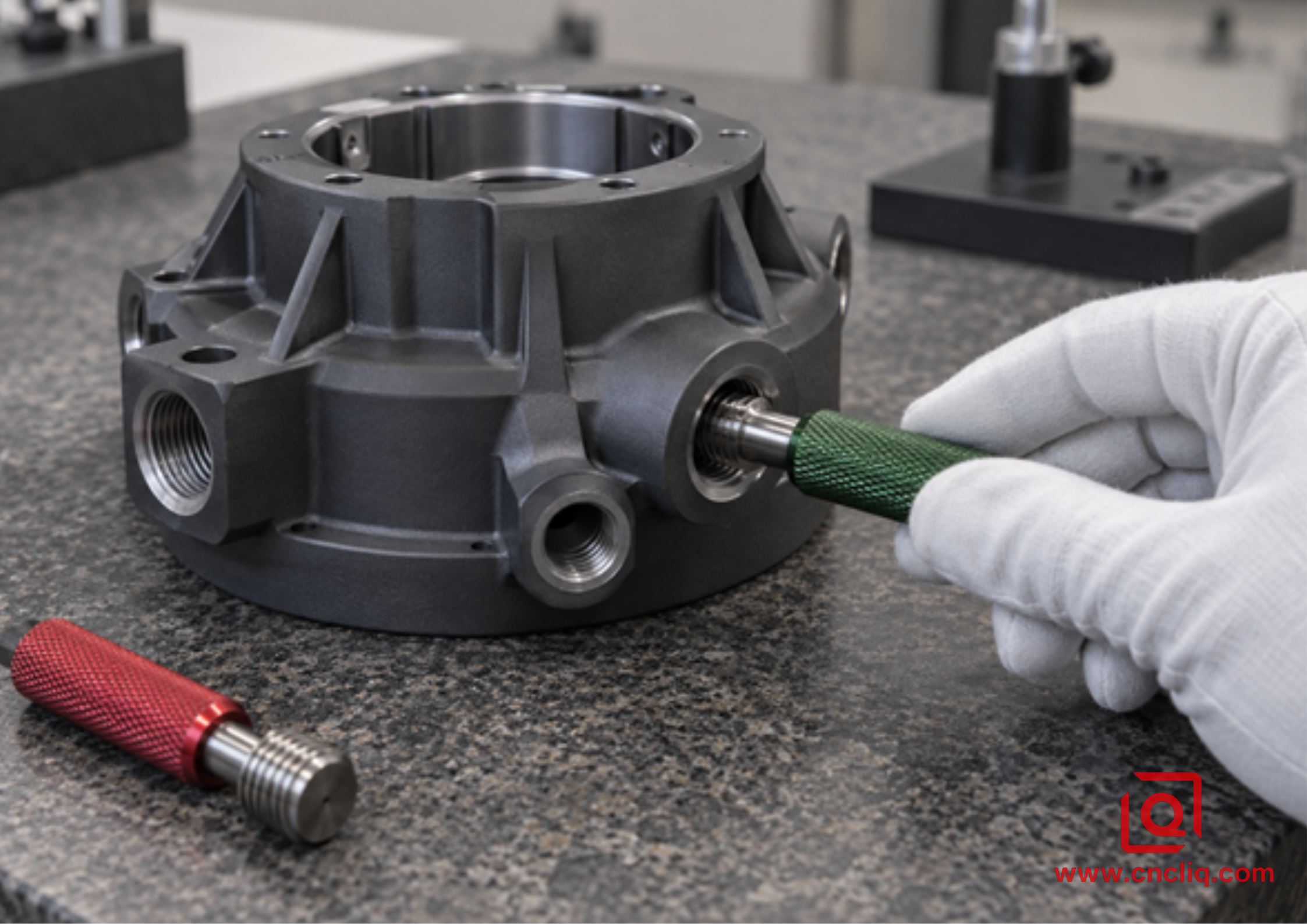
An outside thickness reading answers one question only. It says little about the oxide down a blind tap. Nor is a shop bolt a thread gauge; a loose example can turn while the specified screw later stalls. I like the checks below because each catches a different failure.
1. Before coating, gauge the planned oversize condition. Note the cutter or tap, its offset, and the material lot while the information is still at the machine.
2. At the finishing handoff, compare the certificate request with the mask drawing and rack orientation. Put a witness area where the coating can actually be measured.
3. Rinse, blow out, and inspect blind holes. A grain of blast media or dried chemistry can feel exactly like a tight thread today and become a corrosion site later.
4. Use the specified calibrated GO and NO-GO plugs after the last finish. Sampling belongs to the quality plan; a critical lot may call for every hole to be checked.
5. When friction or service life matters, finish with a controlled assembly or torque check. Record the screw finish. Stainless, bare steel, and zinc-plated hardware do not feel the same in an anodized thread.
A stopped GO plug is a stop sign, not a request for a longer wrench. Forcing it can flake oxide from the flank and make the next attempt look better for the wrong reason. Hold the lot. Check debris first, then the gauge, the raw-thread record, the coating result, and the usable depth before anyone discusses rework.
Anonymous Customer Case: Compact Robotic Actuator Housing
A customer in industrial automation brought us a compact 6061-T6 actuator housing. It carried twelve M6 x 1 taps, two bearing registers, and a 40 micrometer Type III callout. The print said 6H after finish but gave no clue which holes were to be plugged or cut loose beforehand. The first sample told the story: the screws tightened early, and the bearing fits had lost room as well.
The answer was not one oversized tool. Eight cover screws lived inside a sealed cavity, so we plugged those holes and drew the mask edge. Four mounting holes faced the working environment; their flanks needed oxide, so we thread milled them larger. The 40 micrometer film suggested 20 micrometers of outward growth and an 80 micrometer pitch-diameter shift. We used that figure to cut the trial, not to release production.
Those trial pieces went through on the rack intended for production. Back at inspection, the four coated taps met the final plugs and a nearby witness area confirmed the bath. One small radial correction went into the thread-mill path. The drill stayed where it was. We handled each bearing register under a separate diameter allowance instead of mixing the two problems.
What mattered was the route left behind. Cover taps had a mask plan. Exposed taps had a proven tool offset. Both were checked after finish, and nobody chased parts by hand at assembly. The same split works on valve blocks, optical bodies, pneumatic manifolds, and communication hardware. Liqin's documented 6061-T6 CNC-machined aluminum component shows the related material, machining, finishing, and inspection scope.
RFQ Checklist for Internal Threads and Hardcoat Anodizing
1. Supply the native STEP model and the controlled 2D drawing revision.
2. State the aluminum alloy and temper, not only "aluminum."
3. Specify MIL-PRF-8625 Type, Class, coating thickness, sealing condition, and color if applicable.
4. Identify every internal thread by standard, size, pitch, class, engagement length, and blind or through condition.
5. State whether each thread is masked, anodized with pre-compensation, machined after coating, or fitted with an insert.
6. Define whether dimensions and thread gauges apply before or after finishing.
7. Mark masking boundaries, acceptable rack-contact areas, protected bores, sealing faces, and electrical contacts.
8. Provide mating-fastener material and finish, controlled torque, annual volume, inspection reports, and any sample hardware.
If the print already carries those notes, include it with the model. If not, let us mark the risky features before price and lead time are fixed. Ten minutes spent on the mask and gauge plan is cheaper than sorting a finished rack. Send Liqin the drawing and hardcoat callout for DFM feedback and a quotation.
FAQs
1. How much should I oversize an internal thread before 50 micrometer hardcoat anodizing?
Start the worksheet with 25 micrometers of outward growth, which points to about 100 micrometers at pitch diameter on a 60-degree form. Then stop and check the real job. Work backward from the final thread limits, allow for the coating window and pretreatment, and measure a production-style first article. The calculated 100 micrometers is an opening bid, not an automatic tool offset.
2. Can I use a larger tap drill instead of an oversize tap?
Not by itself. A larger tap drill mainly increases minor diameter and reduces thread percentage; it does not reliably create the pitch-diameter allowance needed for coating on both flanks. Use a selected oversize tap or an adjusted thread-mill path when pitch diameter must move, then verify the finished thread with the required GO and NO-GO gauges.
3. Should small internal threads be masked before Type III anodizing?
Often, yes. I lean toward a plug when the tap is fine, deep, difficult to rinse, electrically active, or held to a tight finished class. The catch is easy to miss: the protected flanks are bare aluminum. Balance that exposure against wear, corrosion, service frequency, plug labor, and any permitted conversion coating. Make the choice hole by hole.
4. Is it acceptable to re-tap a thread after hardcoat anodizing?
Yes, but only as a named operation on an approved route. The tap will expose aluminum and work against an abrasive oxide edge; chips and small flakes must be removed afterward. Call out the final gauge, cleaning, and any local protection. If a fitter reaches for a tap only because the batch binds, the process has already failed.
5. What should I send for an accurate hardcoat-thread quotation?
Send a STEP model, controlled 2D drawing, alloy and temper, thread standard and class, finished gauge requirement, coating specification and thickness, mask map, rack-contact restrictions, mating-fastener details, quantities, and required reports. Mark which dimensions apply after finishing. Those details let the supplier price tooling, masking, first-article trials, inspection, and risk without hiding assumptions in the quote.
Summary
The useful lesson is simple: hardcoat steals room at the flanks, and the tap drill cannot give all of it back. Use 4g as the opening estimate for a 60-degree pitch diameter. After that, trust the qualified bath and the coated sample. Keep minor diameter, pitch diameter, masking, and final gauging as separate decisions. Do that work on the print, and the assembly bench should hold no surprises.
Contact Information
Company: Ningbo Liqin Industry Co., Ltd.Daily customer maintenance & after-sales support:service@shturl. zhuwanying@cncliq.com
New inquiry, quotation & order discussion:business@shturl. zhouli@chinaliqin.com
Hotline: +86 18757148656
Disclaimer
All technical articles, material specifications, machining recommendations, and surface treatment details published on this blog are for informational and reference purposes only. Please note that general blog insights do not replace signed technical agreements. Because custom parts vary by material heat numbers, machine calibrations, and specific tolerances, binding quality specs are governed solely by your approved CAD drawings, signed contracts, and formal quality plans.
All customer case studies featured on this blog have been thoroughly anonymized and sanitized. The performance metrics, manufacturing workflows, and imagery displayed serve solely to demonstrate our custom machining capabilities and do not represent a single universal standard for all orders.
Liqin Manufacturing Team
Built on 18 years of precision engineering experience, Ningbo Liqin Industry manufactures high-tolerance metal components for demanding global markets. We operate out of a 6,500 m² production hub equipped with over 150 machines, running 4-axis and 5-axis CNC machining, mill-turn machining, cold extrusion, and pressure die casting under one roof. This setup allows us to manage projects seamlessly, taking parts from initial CAD concepts directly to finalized shipments.
We handle quality control with zero compromise. We treat tight tolerances with the engineering discipline they require. Backed by ISO 9001, ISO 13485, and IATF 16949 certifications, our QA engineers run strict IPQC, FQC, and OQC checks on every single production batch. From CMM dimensional mapping and optical profiling to hardness and salt-spray testing, we validate your critical specs upfront—so you receive drop-in ready components with zero assembly headaches or costly line stoppages. On top of manufacturing, you can rely on us for two-hour response times on new RFQs, direct support for prototype sampling, and smooth export shipping across Europe, North America, Asia, and Oceania.
Welcome your inquiries and samples. Visit our website or contact us directly for a competitive quote!
