 English




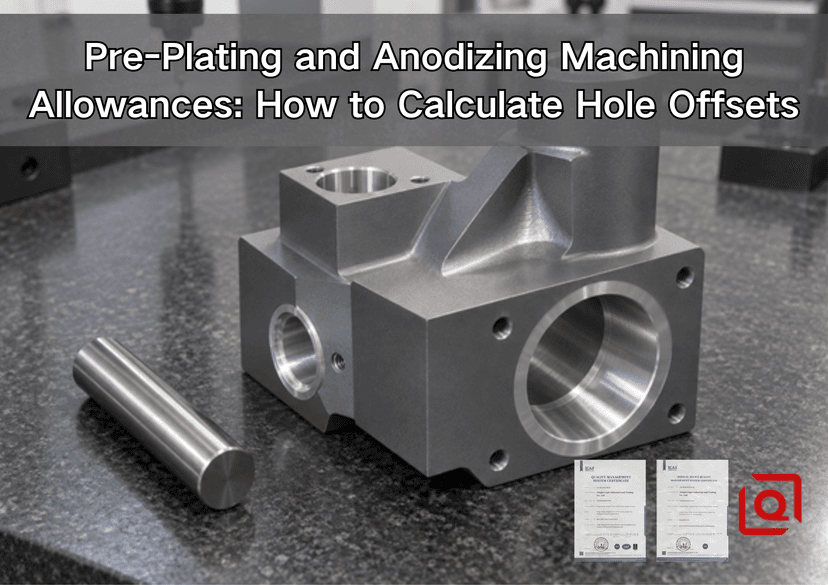
A bore checks good at the machine. A day later it comes back from anodizing and the pin stops at the entrance. It is a familiar sort of rejection. Nothing mysterious occurred: the cut size passed, but the finish used up the assembly clearance. Below is the calculation I would put on the job traveler. After that comes the information missing drawings often leave for the finishing shop to guess.
My first mark on a coated-part print is usually beside the finished bore. I write down its acceptable size after the last tank, rinse, and seal. The prefinish dimension comes afterward, by working the numbers in reverse. That backward check has four inputs: finished fit, coating inside the bore, metal lost in preparation, and the way inspection will be made.
1. The quick answer: allow for both sides of the hole
For a round hole receiving a uniform deposited coating, the starting rule is:
Machined hole diameter = required finished diameter + twice the coating thickness on one wall.
Write 10.000 mm under “after plating.” Beside it, note the local deposit: 0.010 mm. Two coated sides together consume 0.020 mm across the opening. With no measurable preparation loss, the machine must leave 10.020 mm. Written two ways, that is 0.020 mm on diameter and 0.010 mm on radius. Mixing up those two columns has spoiled more than one close fit.
Anodizing needs a different input. Some oxide replaces aluminum below the former surface. The portion that matters to bore closure is the part growing above that surface. A bore has two opposing walls, so the outward-growth allowance appears twice. Oxide lying below the old metal line does not narrow the opening beyond that. Think of the signs physically: etch makes the opening wider; buildup makes it narrower.
These rules describe size changes. They do not automatically specify a CNC control offset. A boring program may use diameter values while another tool compensation field uses radius values. Confirm the programming convention before entering the calculated correction.
2. Plating thickness and anodizing growth are different
Electroless nickel grows on top of the prepared base. An electroplated layer does as well, although its distribution can be quite different. Anodizing is a conversion process: some parent aluminum at the boundary ends up as oxide. Using a plating allowance for an anodized bore, or the reverse, is therefore a bad shortcut.
|
Process |
Useful allowance input |
Shop-floor question |
|
Electroless nickel plating |
Local deposited thickness on each bore wall |
Can fresh solution circulate through the full bore? |
|
Electroplating |
Local deposited thickness, including variation |
How does thickness at the mouth compare with the bore interior? |
|
Type II sulfuric acid anodizing |
Actual outward growth plus preparation loss |
What growth allowance has this alloy and process demonstrated? |
|
Type III hardcoat anodizing |
Outward growth; about half the total film is a common planning assumption |
Is the specified thickness achievable on this internal surface? |
Anoplate's dimensional guide gives about one-third outward growth for Type II and about 45 percent for Type III. On a loose clearance that difference may disappear in the tolerance. On a bearing seat it may use most of the available room. Put the chosen fraction in the finishing review and tie it to the alloy, pretreatment, and bore geometry. Published ratios are planning clues, not inspection limits. A universal “50 percent growth” rule for every anodized part is too crude for a tight bore.
For Type III, NASA JSC PRC-5006, Revision D uses approximately equal penetration and outward buildup as typical Type III behavior. It warns that holes and small openings may receive thinner coating. An external thickness reading therefore does not, by itself, prove the allowance inside a deep bore.
Liqin's anodizing machining tolerances guide provides the broader drawing and fit context. Here, we focus on converting that design intent into a measurable bore size.
3. Put pretreatment into the same calculation
In the lines below, Dm means the bore recorded after machining. Df is the size inspection must accept after finishing. For either wall, e represents metal lost during preparation; b represents coating that projects into the bore. Before touching the calculator, put all four values in one unit.
Df = Dm + 2e - 2b
Dm = Df + 2b - 2e
For deposited plating, b is the deposited thickness. With anodizing, obtain b by multiplying the local oxide thickness by the agreed outward-growth fraction. There is one trap here. Be careful with actual before-and-after data. Because that reading spans the whole route, the preparation effect is already inside it. Leave e out when using such net data.
For reference, 1 µm converts to 0.001 mm. On that basis, 25 µm is written 0.025 mm. Putting the conversion on the traveler is a small habit, but it has caught misplaced decimals before a tool was offset.
Here is a plating example. The drawing asks for 12.000 mm finished, local nickel is 12 µm per wall, and the agreed preparation loss is 2 µm per wall. The arithmetic on the traveler would read 12.000 + 0.024 - 0.004. The answer is 12.020 mm before plating. Without preparation loss, it would be 12.024 mm. That 2 µm figure belongs only to this example. Do not carry it onto another job as though it were a process constant.
Now take a print calling for a 20.000 mm bore after 40 µm Type III hardcoat. With the one-half factor used here, the coat takes 20 µm of radius. This example assigns no additional loss to preparation. Across the bore the change totals 0.040 mm; the machining box should therefore show 20.040 mm nominal. If someone doubled the entire film instead, the instruction would read 20.080 mm. Under the stated assumptions, the finished hole would then be too large.
No reliable value for process loss? Put a representative trial through the finisher and measure it. Do not choose a convenient etch number to make the arithmetic fit the drawing.
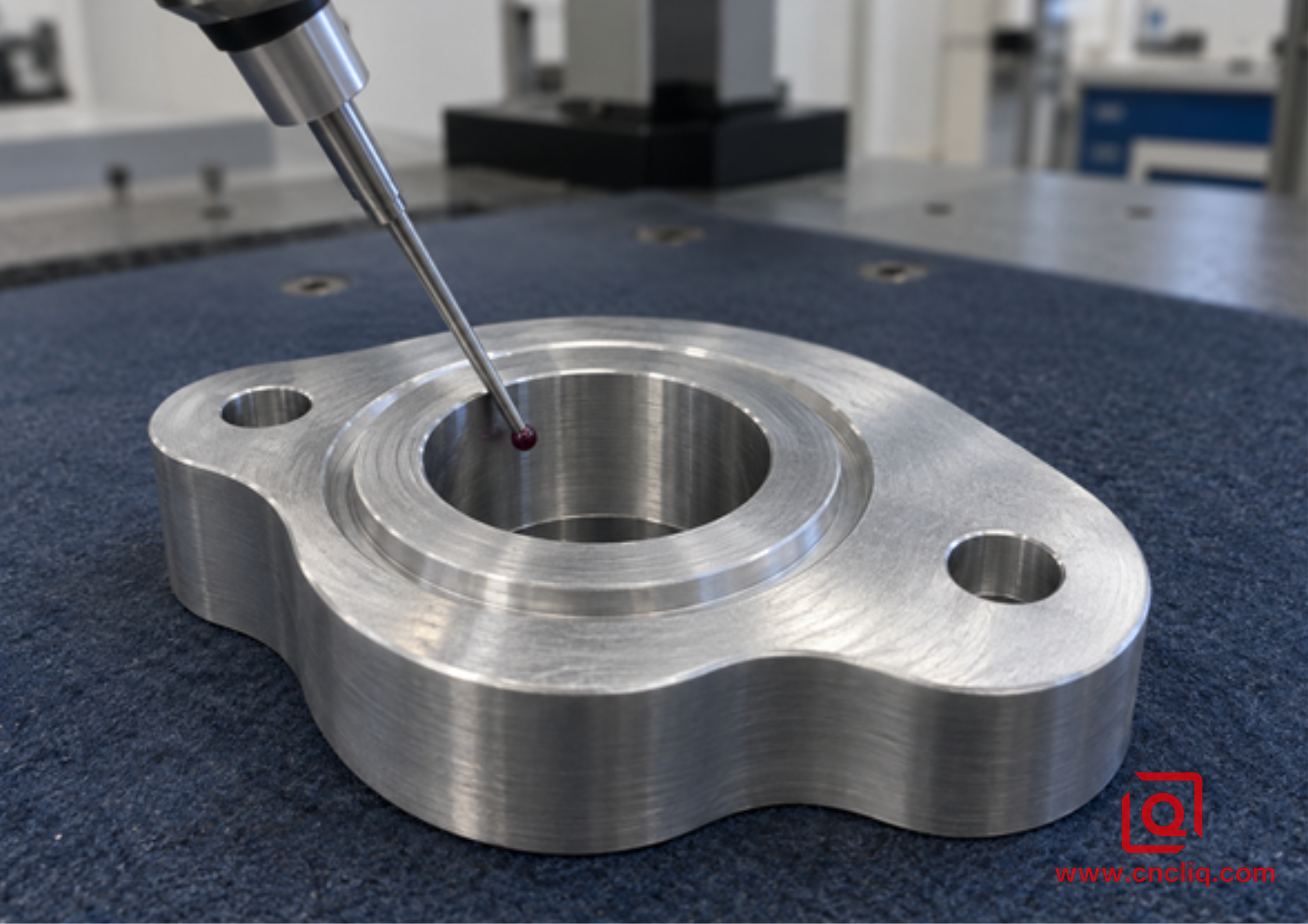
Measure the bore at defined depths before finishing so the allowance can be checked against the finished result.
4. Check both limits before settling on a target
A nominal offset can be correct while the production plan still fails. Real batches carry variation from machining and from coating. The smallest and largest finished bores still have to land inside the drawing limits.
Use 10.000 to 10.020 mm as the finished range for this check. The finisher's agreed local deposit is 0.008 to 0.012 mm on each wall. For this first example, preparation loss is negligible and opposite walls have the same stated limits.
|
Calculation |
Result |
Meaning |
|
10.000 + twice 0.012 |
10.024 mm |
Minimum permitted machined diameter |
|
10.020 + twice 0.008 |
10.036 mm |
Maximum permitted machined diameter |
|
Midpoint of those limits |
10.030 mm |
Nominal machining target |
|
Remaining machining window |
0.012 mm total |
Equivalent to plus or minus 0.006 mm before additional reserves |
Check the worst cases. At the lower corner, subtract the 0.024 mm diametral deposit from a 10.024 mm machined hole. The result is exactly 10.000 mm. For the upper corner, 10.036 mm minus the 0.016 mm diametral deposit gives 10.020 mm. Those answers just touch the acceptance limits. There is no spare room in them for gauge uncertainty, taper, or another unlisted source of spread.
More generally, the lower machining limit equals the lower finished limit plus twice the maximum buildup, minus twice the minimum preparation removal. The upper machining limit equals the upper finished limit plus twice the minimum buildup, minus twice the maximum preparation removal. Sometimes the two calculated limits cross. When that happens, shifting the boring target cannot rescue the plan; its assumed process window is impossible.
It is worth doing this check before sending a “hold it tighter” note to machining. The coating may already have spent the tolerance. The remaining choices are process choices: reduce the local coating range, mask the feature, approve sizing after treatment, or revisit the fit. If the two sides do not coat alike, enter each wall separately and add them. Doubling an average can hide the worst condition.
5. Turn the calculation into a usable drawing
On the drawing, place “dimension applies after finish” beside the critical bore rather than leaving it in an email. The same release package should name the alloy and temper, finish specification with revision, local thickness band, seal or other post-treatment, and every masked surface.
Do not confuse the acceptance size with the shop's internal prefinish target. They serve different purposes. The finished bore belongs on the controlled product drawing. The calculated pre-finish range can sit on an approved operation drawing or control plan, with revision control linking the two, unless the governing specification requires both on the product drawing.
Include the mating component. A shaft that also receives plating grows while its hole shrinks. The assembly loses clearance from both changes. Consider both mating pieces coated by 10 µm per surface. The hole loses 20 µm on diameter, while the shaft gains 20 µm. The assembly has therefore surrendered 40 µm of diametral clearance.
Material substitutions need review, too. The shop discussion should also name the alloy. The behavior covered in our 6061-versus-7075 anodizing article is one reason that line on the print matters. A previous report can be useful. Before copying its offset, compare the alloy, pretreatment, rack setup, finish callout, and bore shape one by one. If those changed, the old offset is evidence, not a setting.
For quotation, I would send five things together: model, controlled print, mating limits, batch quantity, and any existing measurements taken before and after finishing. The reply should state two ranges, one for machining and one for final acceptance. If the ranges are absent, there is probably still an assumption to settle.
6. Coat it, mask it, or size it later?
On a sliding or exposed surface, the bore coating may be doing real work against wear or corrosion. A dowel hole or bearing seat may have a different priority; adding film there can introduce variation without adding useful function. Decide by function before asking the shop to compensate every hole automatically.
|
Route |
When it can help |
What must be agreed |
|
Coat the bore and pre-compensate |
The coating is required on the working surface |
Local thickness, finished size, and inspection access |
|
Mask the precision bore |
Bare aluminum is acceptable at the fit |
Mask boundary, edge condition, and corrosion protection |
|
Machine after finishing |
The design permits exposed substrate at the resized surface |
Remaining coating coverage, burr control, and final acceptance |
|
Use a designed insert or bushing |
The assembly needs a separately controlled bearing surface |
Installation method, retention, and material compatibility |
The masking note has to follow the feature through preparation as well as coating, with the boundary shown on the print. For example, installing a plug after etching protects the anodizing step only. The earlier metal loss remains. Mark the boundary too. The bore edge, chamfer, and any counterbore should not be left to the masker's interpretation.
A reamer used after anodizing cuts through the oxide along the corrected surface. The gauge size may be recovered, yet the surface protection is no longer the one shown by a fully coated bore. Get that route approved before production, especially when the drawing requires full coating coverage.
Hardcoat thickness should follow the service requirement rather than a “thicker is always better” assumption. Liqin's recent Type III hardcoat wear and hardness guide supports that discussion. A fit problem is easier to solve when coating coverage and wear requirements are decided together.
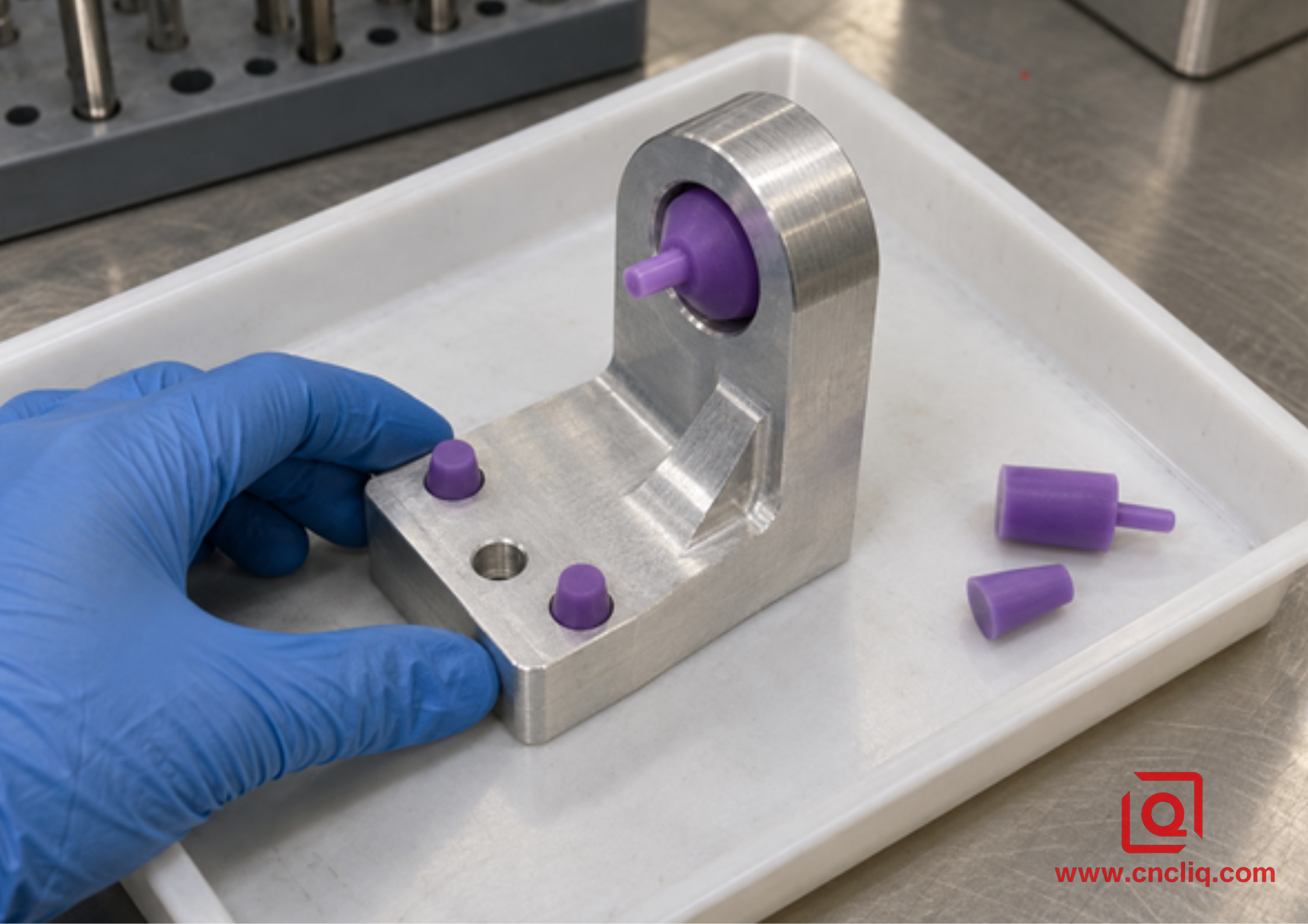
Define the masking boundary, including chamfers and counterbores, before the batch reaches surface treatment.
7. Watch deep bores, threads, and bore position
Electroless nickel can follow complicated shapes well, provided active solution can reach and leave the surface. That condition appears in the published scope of ASTM B733: uniformity is associated with free circulation of plating solution. A blind pocket can trap gas or stagnant solution, so it belongs on the finisher's review list. With electroplating there is also current distribution to consider. An open edge and a deep recess seldom see identical conditions.
Ask where thickness will be checked. A flat witness coupon may confirm bath behavior without reproducing the conditions inside a long narrow passage. For difficult geometry, agree on representative trials, accessible measurement locations, or sacrificial sections where justified.
Threads need their own calculation. As illustrated in Micron Coatings' nickel thickness guide, a symmetrical 60-degree thread has a pitch-diameter change of approximately four times the deposited thickness measured normal to the flank. Internal pitch diameter decreases; external pitch diameter increases. This differs from the two-wall rule for a plain bore. Confirm the thread class, tap allowance, coating condition, and final gauging.
Do not shift a hole center merely because its diameter needs compensation. An equal amount on opposite walls closes the bore symmetrically; it does not, by itself, relocate the axis. Size and location are still two separate results on the report. A heavy side, a distorted part, or a damaged datum may shift the functional relationship even when the size looks acceptable.
8. An illustrative customer case: an anodized manifold body
The following anonymous scenario is a constructed engineering example, not a documented customer order. It builds on the ported geometry and custom machining route shown in Liqin's anodized hydraulic manifold product. The guide bore, Type III requirement, and dimensions below are selected for this example; they are not specifications claimed for that catalog product.
The example print has a 0.020 mm acceptance band after Type III treatment: lower limit 20.000 mm, upper limit 20.020 mm. For teaching purposes, local film is taken as 36–44 µm. The calculation uses one-half outward growth and assigns no separate preparation removal. The 36 µm film case removes 0.036 mm from the opening. The 44 µm case removes 0.044 mm.
Add the worst closure to the lower finished limit and the lightest closure to the upper limit. The resulting pre-anodize range is 20.044–20.056 mm. Its midpoint is 20.050 mm and the available machine window is 0.012 mm. Any reserve for measurement or another source of spread must come out of that window. If the shop bored straight to 20.010 mm and ignored growth, the treated bore would fall below the specified range in this model.
A sensible route machines the body and its passages first. The guide feature is finish-bored afterward. Next, clear the burrs at intersecting passages and clean the channels. Record the bore at each agreed depth before it leaves for finishing. Process a representative trial through anodizing and inspect the finished bore. The operation plan should also identify the threaded ports and locating surfaces that need approved masking.
If trials do not support the assumed internal growth range, revise the process before releasing the batch. A different allowance cannot fix uncontrolled coating variation. Quoting machining and finishing together makes the fit discussion happen while the process can still be changed.
9. Inspect where the fit actually works
Choose the inspection depths in advance and reuse them after treatment. Readings taken at unrelated positions cannot show the actual change. The entrance reading is only one point on a long bore. Read near each end and at useful points through the working length to see taper or local buildup. Let feature access and allowed error drive gauge selection. A bore gauge may suit an open feature; an air gauge or another validated method may suit a different one.
A calibrated limit plug is useful on the floor because the operator gets a simple pass/fail check of functional size. It says nothing about lobing, cylindricity, or where the bore axis sits relative to the datums. Call out separate measurements when those geometric controls matter. Let the part and gauge reach the agreed measurement temperature, and keep the bore clean before judging the fit.

Verify the finished bore and the mating component under the agreed inspection conditions.
The first accepted lot should leave a usable record: drawing revision, material, route, local thickness evidence, bore readings, and mask boundaries. Attach that record to the operation sheet. On the next lot, changes in material or finishing will then be visible instead of buried in email. For a new quotation, mark the bores that must assemble as finished and send Liqin the controlled critical-fit drawing.
FAQ
1. What pre-plating allowance should I add to a bore?
Begin with the deposit specified at the bore wall. Add the two walls, then correct for verified preparation loss and check the full permitted thickness band. Add the walls directly: 10 µm + 10 µm = 20 µm less bore diameter. Base the figure on coating in that bore; a reading from an easy outside face may describe a different condition.
2. How much bore closure comes from a 50 µm hardcoat?
No. Under the stated 50/50 model, 25 µm of a 50 µm film sits outside the former metal line. Two sides at 25 µm produce 50 µm of bore closure. Preparation, if separately verified, is applied afterward. The finisher should verify the local response on a representative feature or trial part. Use that fraction to size the first trial, then judge production against the agreed drawing and measured process data.
3. Is an H7 bore practical after anodizing?
Potentially, but the answer depends on nominal diameter, the applicable H7 limits, local growth variation, machining capability, and inspection uncertainty. Specify the fit after finishing. When coating spread consumes the H7 window, a nominal offset will not solve it. Review masking, local process control, or an approved sizing route.
4. Should this feature be masked, or cut to size after anodizing?
Neither route wins on every part. Masking brings labor and handling; post-finish cutting brings another setup, more inspection, and a risk to nearby coating. Quantity, geometry, mask access, and coverage requirements determine the better route. If both routes meet the print, quote them against the same quantity and acceptance criteria.
5. What information makes a finishing RFQ useful?
Send the model and controlled print, then list alloy and temper, finished bore limits, mating size, coating callout, local thickness band, mask boundaries, quantity, and inspection method. Identify whether dimensions apply before or after treatment. Previous measurement data is especially helpful when replacing a supplier or troubleshooting a fit.
Summary
Calculate hole offsets from the required finished fit. For plating, count the deposit on both bore walls. For anodizing, use outward growth. Keep verified preparation loss as its own term. Finally, run the worst corners of the tolerance, settle coating coverage and inspection locations, and put the decisions in the RFQ. Machining and finishing can then aim at one agreed result.
Contact Information
Company: Ningbo Liqin Industry Co., Ltd.
Daily customer maintenance & after-sales support: service@shturl. zhuwanying@cncliq.com
New inquiry, quotation & order discussion: business@shturl. zhouli@chinaliqin.com
Hotline: +86 18757148656
Disclaimer
All technical articles, material specifications, machining recommendations, and surface treatment details published on this blog are for informational and reference purposes only. Please note that general blog insights do not replace signed technical agreements. Because custom parts vary by material heat numbers, machine calibrations, and specific tolerances, binding quality specs are governed solely by your approved CAD drawings, signed contracts, and formal quality plans.
All customer case studies featured on this blog have been thoroughly anonymized and sanitized. The performance metrics, manufacturing workflows, and imagery displayed serve solely to demonstrate our custom machining capabilities and do not represent a single universal standard for all orders.
Liqin Manufacturing Team
Built on 18 years of precision engineering experience, Ningbo Liqin Industry manufactures high-tolerance metal components for demanding global markets. We operate out of a 6,500 m² production hub equipped with over 150 machines, running 4-axis and 5-axis CNC machining, mill-turn machining, cold extrusion, and pressure die casting under one roof. This setup allows us to manage projects seamlessly, taking parts from initial CAD concepts directly to finalized shipments.
We handle quality control with zero compromise. We treat tight tolerances with the engineering discipline they require. Backed by ISO 9001, ISO 13485, and IATF 16949 certifications, our QA engineers run strict IPQC, FQC, and OQC checks on every single production batch. From CMM dimensional mapping and optical profiling to hardness and salt-spray testing, we validate your critical specs upfront—so you receive drop-in ready components with zero assembly headaches or costly line stoppages. On top of manufacturing, you can rely on us for two-hour response times on new RFQs, direct support for prototype sampling, and smooth export shipping across Europe, North America, Asia, and Oceania.
Welcome your inquiries and samples. Visit our website or contact us directly for a competitive quote!
