 English




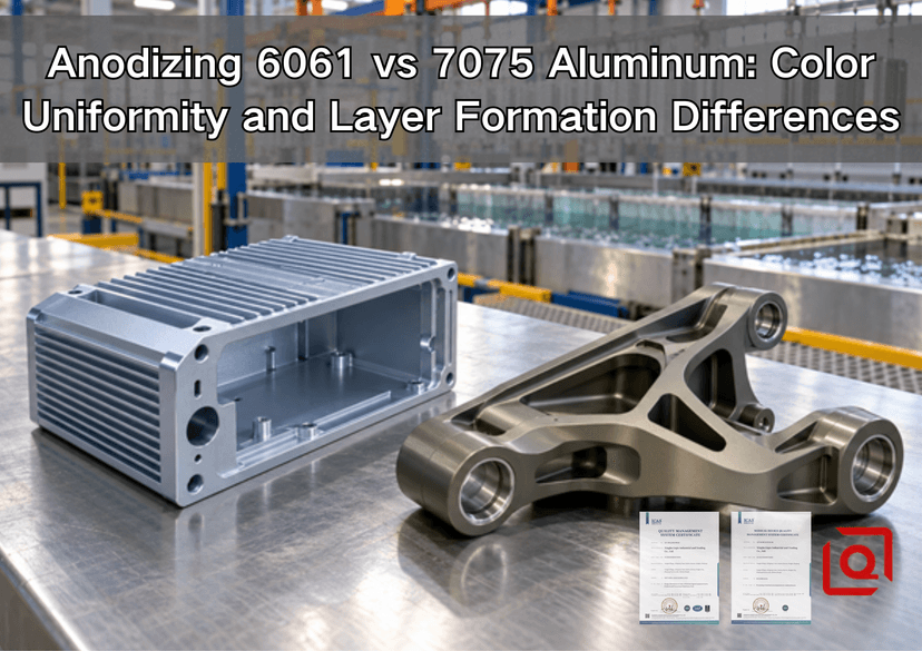
Have you ever approved a sample, opened the production carton, and then found a silver 6061 housing beside a bronze-tinted 7075 link? It is frustrating, but it is not random. This guide follows the part from machined metal to sealed oxide, showing where color, film build, and fit can drift. It also gives buyers a drawing and RFQ framework that a machine shop and anodizer can use without guesswork.
For appearance-led work, most teams begin with 6061. Hold the stock lot, surface preparation, film thickness, dye, and seal step steady, and its color is easier to predict. 7075 accepts Type III hardcoat too, yet its zinc and copper make the reaction more sensitive. A clear film may look darker or warmer; black can carry an undertone. Choose 7075 for the load case, not simply because you want it to resemble 6061.
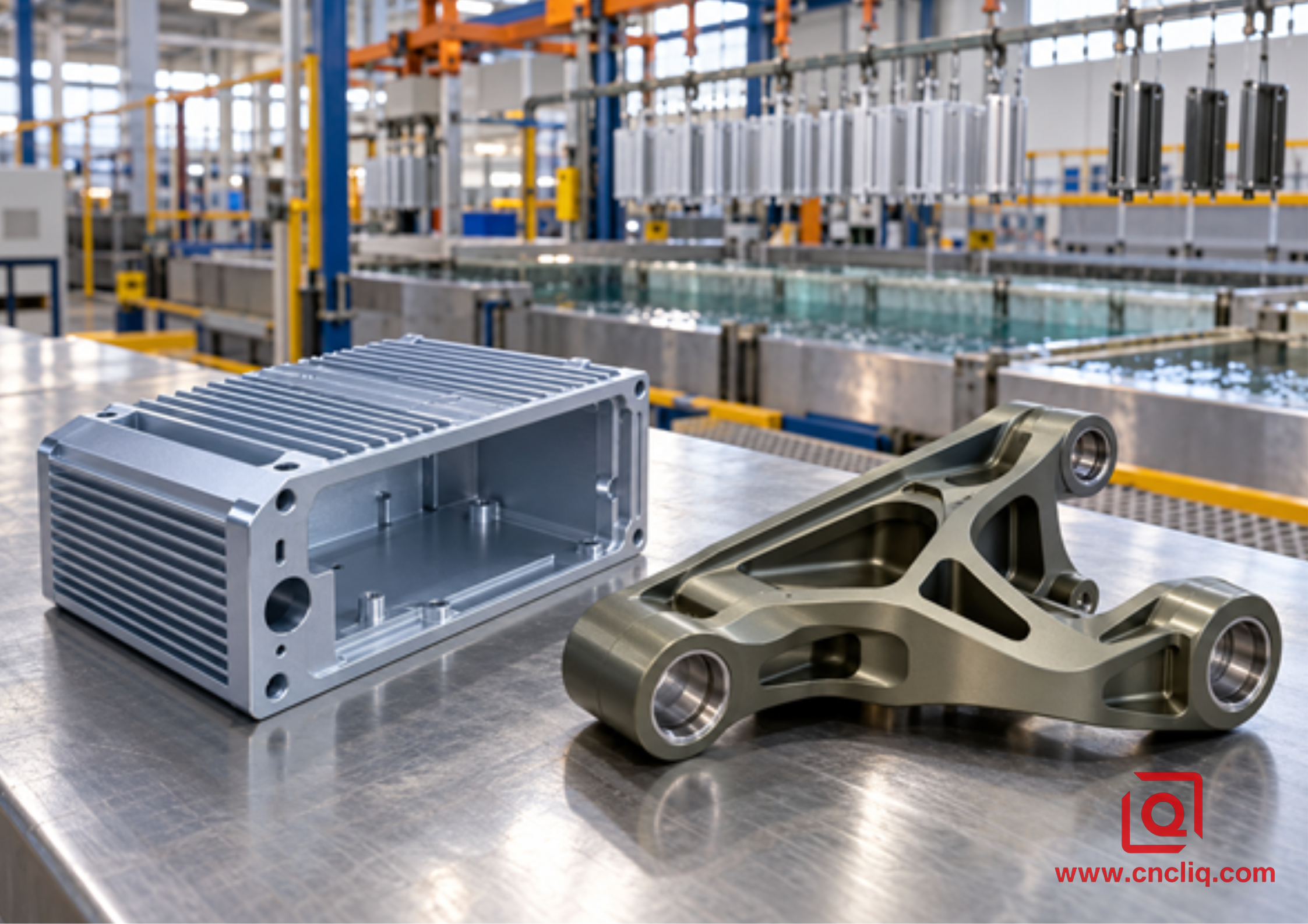
Cover image: newly designed 6061 enclosure and 7075 linkage beside an anodizing line
Quick Comparison: 6061 vs 7075 After Anodizing
|
Engineering question |
6061 aluminum |
7075 aluminum |
Practical decision |
|
Main alloying system |
Magnesium and silicon |
Zinc, magnesium, and copper |
Chemistry changes the natural oxide tone and dye response |
|
Typical natural Type II appearance |
Clear silver to light gray |
Gray, yellow-brown, bronze, or olive-gray |
Do not approve color from an alloy name alone |
|
Dyed color consistency |
Generally easier to control |
More likely to look muted or shift between lots |
Use production-alloy limit samples for cosmetic work |
|
Type III hardcoat appearance |
Dark gray, thickness dependent |
Darker gray, bronze, or olive, often more variable |
Treat natural hardcoat as a functional finish, not a fixed color |
|
Layer-building behavior |
Usually stable across a qualified process window |
More sensitive to current density, temperature, local chemistry, and microstructure |
Run alloy-specific process settings and witness coupons |
|
Best fit |
Housings, brackets, panels, general precision parts |
Highly loaded links, fixtures, structural parts, aerospace-style hardware |
Select alloy for mechanical duty first, then engineer the finish |
|
Main purchasing risk |
Lot-to-lot shade or texture drift |
Color drift plus greater risk of nonuniform appearance |
Separate functional acceptance from cosmetic acceptance |
No comparison table can promise a shade. The Aluminum Anodizers Council identifies alloy, temper, gloss, surface structure, and coloring method as appearance variables. It also notes the generally good anodizing response of 6xxx alloys and the blue-gray to mottled brown-black tones possible on 7xxx stock. Use that guidance as a starting point, never as a color chip.
1. Why Alloy Chemistry Changes the Anodized Surface
Think of anodizing as converting the skin of a part, not painting over it. The aluminum becomes the anode; current travels through the electrolyte, and surface metal converts to aluminum oxide. The unsealed layer contains pores. Dye enters those pores, then sealing closes or stabilizes them. Since the film grows from the metal itself, the condition underneath still matters.
Magnesium and silicon do most of the alloying work in 6061. The result balances strength, machinability, corrosion behavior, and a surface that normally behaves well in the tank. That combination explains its use in housings, covers, frames, and brackets. Even so, 6061 is not a color guarantee. Temper, extrusion history, billet heat, grain direction, cutter tracks, and hand blending can all remain visible after finishing.
Now look at 7075. Zinc is the main alloying element, supported by magnesium and copper. Published limits commonly place zinc at 5.1 to 6.1 percent and copper at 1.2 to 2.0 percent, although the certificate for the purchased heat controls the job. These elements do not occupy one perfectly uniform phase. During cleaning, deoxidizing, and anodizing, particle-rich areas can dissolve or leave smut differently from nearby aluminum. The coating may pass a thickness check and still scatter light unevenly. Many 7075 color complaints begin there.
You notice the difference when the pieces meet at assembly. One cutter produced both faces. One batch of media blasted them. They even shared a dye bath. Still, the 6061 panel appears neutral and the 7075 arm looks warmer. The recipe did not change; the starting metals did.
The public Aluminum Association overview of alloy series confirms the basic metallurgy: 6xxx alloys use magnesium and silicon, while zinc is the primary alloying agent in 7xxx alloys. For finishing behavior, the Aluminum Anodizers Council alloy-and-temper guidance is more direct about 6xxx response and the variable gray-to-brown appearance of 7xxx material.
2. The Layer Forms in the Same General Sequence, but Not at the Same Rate
A traveler can show the same seven process boxes for both alloys. Inside those boxes, however, their response begins to separate.
1. Cleaning comes first. Coolant mist, polishing compound, fingerprints, and shop dust all have to leave the part. A film that is almost invisible at the bench can return later as a patch in the dye.
2. Etching removes a small amount of metal and knocks down the shine. More time is not automatically better. If the etch is too strong or too long, it can soften edges, increase material loss, and expose differences within the alloy.
3. Deoxidizing and desmutting clear away what etching leaves behind. With copper-bearing material or stock rich in zinc, this is more than a rinse. Residue left on the surface can disturb oxide formation before the main anodizing step even begins.
4. A rack has two jobs: hold the part and carry current. Let a contact loosen in the bath and resistance rises; a thin or burned patch may follow. The contact will also leave a witness mark. Decide where that mark belongs before the load reaches the tank.
5. On the line, acid strength, bath temperature, current density, voltage, agitation, and time operate as one system. When the bath drifts, turning a single dial rarely puts the process back on track.
6. For a Class 2 finish, dye enters while the pores remain open. The shade depends on far more than a dye name. Pore structure matters. Film thickness matters. So do pH, temperature, concentration, and dwell time.
7. Sealing closes the sequence. Too little sealing can reduce stain and corrosion resistance.Excess heat or unstable chemistry can shift gloss and color. Poor rinsing creates another risk: trapped chemistry may not show itself until later.
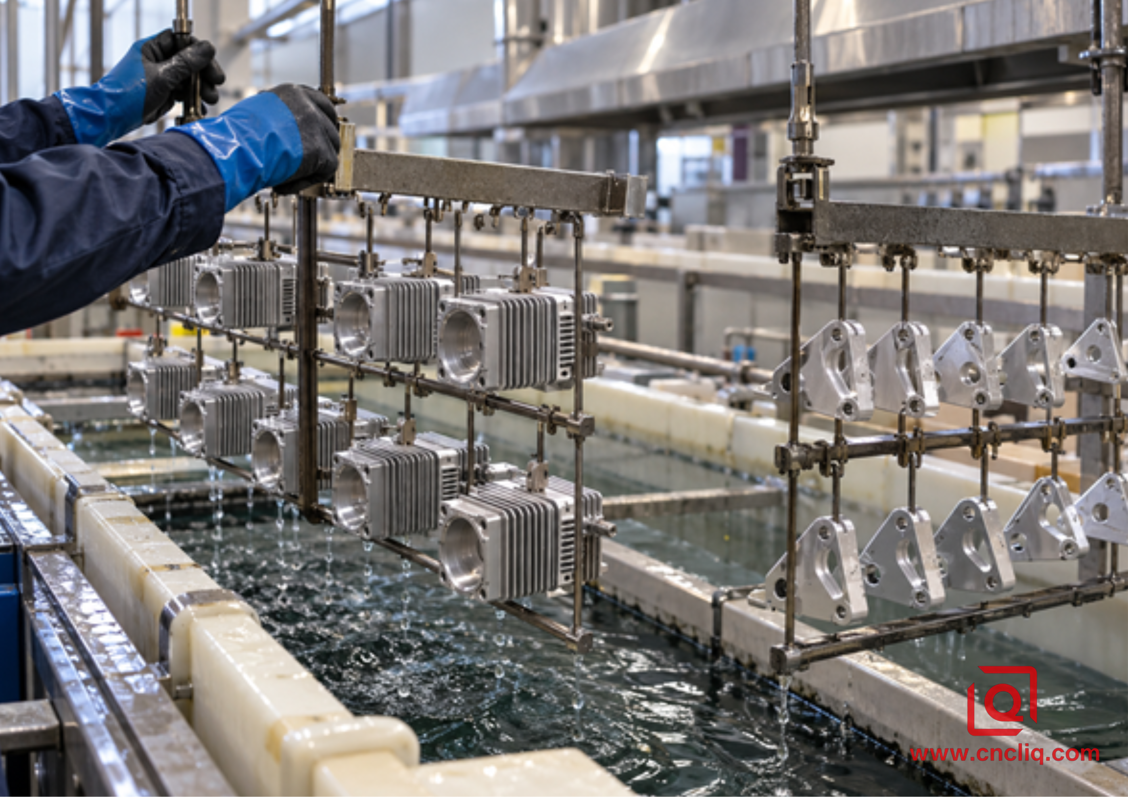
Process image: unique 6061 housings and 7075 clevis brackets being racked at an anodizing line
The NASA/JSC PRC-5006 process specification gives two useful lessons for buyers. First, Class 1 means non-dyed and Class 2 means dyed; the required Class 2 color belongs in the drawing note. Second, surface texture is replicated rather than leveled, so a smooth glossy finish must start smooth, while a matte finish requires a defined mechanical preparation. Anodizing will not hide tool marks, weld variation, scratches, or an uneven bead blast.
For a broader comparison of finish routes, Liqin’s guide to surface finishes for custom aluminum OEM parts places anodizing beside other practical options. If the real requirement is an exact color across dissimilar alloys, powder coating versus anodizing is also worth reviewing before the drawing is frozen.
3. Type II and Type III Do Different Jobs
MIL-PRF-8625 is an active U.S. performance specification covering anodic coatings for non-architectural aluminum applications. In its terminology, Type II is conventional sulfuric acid anodizing and Type III is hard anodizing. Class 1 is non-dyed; Class 2 is dyed. Those labels define the route, not a guaranteed shade.
|
Item |
Type II sulfuric anodize |
Type III hardcoat anodize |
|
Main purpose |
Corrosion protection, appearance, dyeing, general service |
Wear resistance, thicker functional oxide, dielectric or sliding service |
|
Common commercial planning range |
Often about 5 to 25 micrometers, subject to drawing and supplier capability |
Commonly 25 to 50 micrometers, with thicker builds possible only by agreement |
|
Color behavior on 6061 |
Clear silver to gray; broad dyed-color capability |
Gray to dark gray as thickness rises |
|
Color behavior on 7075 |
Yellow-gray, bronze, or olive undertone may appear |
Natural dark bronze-gray or olive tone is common; black can be less neutral |
|
Dimensional concern |
Fits, threads, bores, sealing faces |
Stronger effect on close fits, threads, sharp edges, and fatigue-sensitive geometry |
|
Buyer action |
State alloy, pretreatment, thickness, color, seal, masking, and inspection |
Add final-dimension strategy, edge radii, rack zones, and alloy-specific sample approval |
These are planning ranges for the shop, not automatic MIL-PRF-8625 rules. The controlled drawing, purchase specification, and qualified supplier process establish the actual target. A note that says only clear anodize or black hardcoat leaves too much open. Name the governing specification and revision, Type, Class, thickness target or range, color, seal, masking, permitted rack zones, and required tests.
Oxide grows both into the substrate and above the original surface. For early DFM, industry commonly estimates about 50 percent penetration and 50 percent outward buildup per surface. The AAC reference guide presents that split as a generally accepted rule, while warning that alloy and process change the result. With a 20-micrometer film, roughly 10 micrometers may build outward on each bore wall, taking about 20 micrometers from the diameter. That is enough to disturb a dowel fit or bearing seat.
Use the estimate for early tolerance planning, then replace it with data from the actual supplier, alloy, thickness, and geometry. Liqin’s Type III anodizing DFM guide covers masking, coating allowance, and close-fit planning in more detail.
4. What Actually Controls Color Uniformity
Color problems seldom begin in the dye tank. By the time a rack reaches dye, choices about stock, texture, cleaning, and setup may already have decided the outcome.
Hold the Alloy, Temper, and Material Lot
Start with the stock; it is the foundation. Asking one dye to make 6061 and 7075 identical is asking chemistry to solve a metallurgy problem. When cosmetic limits are tight, keep the temper and heat lot consistent within each grade. Link the mill certificate to the traveler, mark mating parts as a set, and move that set through preparation and finishing together.
Define the Starting Texture
Next, lock down the texture. A turned ring reflects light differently from a milled plate, and vibratory finishing does not look like brushing or bead blasting. Name the preparation and protect it between operations. In the blast cabinet, media type and cleanliness matter alongside pressure, distance, angle, and dwell. Dirty media or too much time in one spot can leave a visible patch.
Control Pretreatment by Alloy
Pretreatment must follow the alloy, not shop habit. A long alkaline etch may give one job a clean matte surface and streak the next. On 7075, deoxidizing and desmutting must remove zinc- and copper-bearing residue without attacking the part unnecessarily. Find that process window on a production-alloy coupon, not on the full batch.
Keep Electrical Contact Stable
We check the rack plan before release. The contact has to carry the required current without heating or working loose, and it will leave a mark. Put an allowed, hidden contact zone on the drawing. If the print gives the rack nowhere to touch, the shop still has to choose a face, and it may be cosmetic.
Approve a Physical Range, Not a Screen Image
We never approve color from a phone screen. Cameras alter white balance, monitors add another shift, and room lighting finishes the distortion. Use a signed physical master, with light and dark boundary samples where needed. Record the lamp, viewing distance, and angle. L*, a*, b* readings help, but Delta E is not a universal pass value. Agree on the instrument, geometry, locations, and numerical window.
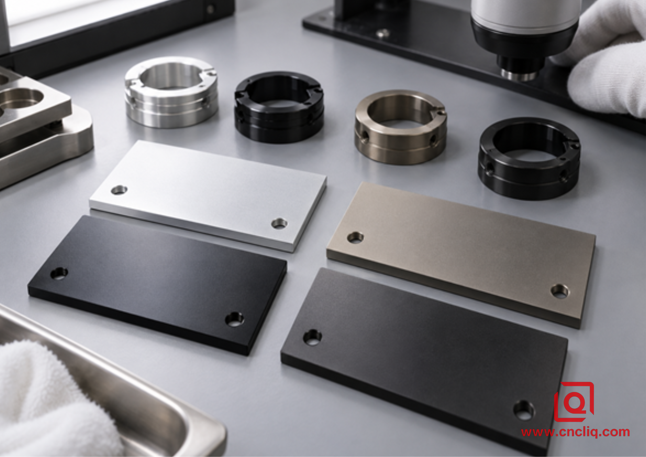
Inspection image: unmarked 6061 and 7075 anodized coupons under controlled neutral light
Liqin’s clear anodize versus black anodize guide explains why clear only means non-dyed and why black dye does not turn alloy variation into an identical substrate. For alloy selection before machining, see CNC milling 6061, 7075, or 5052 aluminum.
5. A Drawing Note That Prevents Expensive Guesswork
Use the next table as an RFQ checklist, not a block of text to paste unchanged onto every drawing. Adapt each field to the actual part.
|
Drawing or RFQ field |
What to state |
Why it matters |
|
Base material |
Exact alloy, temper, product form, and certificate requirement |
Confirms the substrate that will form the oxide |
|
Governing specification |
MIL-PRF-8625 or another applicable standard, including revision policy |
Aligns process and acceptance language |
|
Type and Class |
Type II or III; Class 1 or 2 |
Separates coating duty from dye choice |
|
Thickness |
Target or allowable range and measurement method |
Controls wear, color depth, and dimensional growth |
|
Pretreatment |
As-machined, brushed, polished, or controlled bead blast |
Establishes texture and gloss |
|
Color acceptance |
Named color plus approved physical samples and viewing method |
Reduces subjective rejection |
|
Critical dimensions |
Final-after-finish dimensions, masked features, or pre-compensation plan |
Protects bores, threads, datums, and seals |
|
Rack locations |
Allowed contact zones |
Prevents visible or functional witness marks |
|
Seal and tests |
Seal route plus required thickness, corrosion, wear, or adhesion checks |
Matches inspection to the actual service risk |
|
Traceability |
Material heat, traveler lot, sample status, and inspection report |
Makes repeat orders easier to reproduce |
For quoting, send the 3D model, controlled 2D drawing, quantities, finish target, cosmetic map, functional faces, and mating-part details. If alloy selection remains open, share the load, environment, and assembly conditions rather than choosing the stronger grade by reflex. Liqin can then review machining and finishing as one process before stock is cut.
6. Choosing the Alloy by Function, Not by Color Alone
Choose 6061 when the part needs balanced strength, good corrosion behavior, practical cost, reliable machining, and a repeatable cosmetic anodized finish. It is a strong default for instrument housings, heat-sink bodies, motor covers, optical mounts, automation brackets, and telecom hardware. Liqin’s verified 6061-T6 5G surge-arrester electrode shows the company’s scope in cold extrusion, precision CNC finishing, deburring, inspection, and surface treatment for compact aluminum components.
Choose 7075 when structural strength, thread retention, stiffness, or weight reduction justifies the higher material and finishing risk. Typical candidates include highly loaded clevises, robotic links, aerospace-style brackets, fixture elements, and prosthetic hardware. Liqin’s 7075 prosthetic flange locking T-nut is a relevant product example because it combines high-strength stock, precision multi-axis machining, deburring, and anodizing requirements.
If two visible parts must match perfectly, using one alloy and one material lot is the cleanest strategy. If mechanical requirements force a 6061 and 7075 combination, approve different natural tones, select an opaque coating system, or define a realistic range after production-alloy trials. The aluminum product category provides additional examples of the material and process scope available for custom work.
7. Anonymous Customer Case: Mixed-Alloy Optical Positioning Assembly
One anonymous optical-positioning project makes the risk easy to see. The assembly used a 6061-T6 controller housing and two short 7075-T651 load links. Its print called for Type II Class 2 black everywhere and asked the assembled parts to look uniform. Close dowel bores and two ground pads were shown, but rack zones, masking, after-finish dimensions, blast texture, and a workable color limit were missing.
Review uncovered three conflicts. The two alloys did not take black in the same way. Replacing the links with 6061 would require a fresh load check. And the all-over anodize note clashed with both the dowel fits and electrical pads. One short finish callout was being asked to satisfy incompatible needs.
The revised route kept each alloy where the design needed it. All visible faces received one controlled satin blast, and coupons from both production heats went through trials. The customer accepted a slightly warmer black range for 7075. Dowel bores, selected threads, and one ground pad were masked. Only after coupon data showed actual growth did the machinist adjust pre-anodize dimensions. Rack contacts moved to hidden faces.
Final inspection ran in two lanes. CMM results answered the assembly question; coating readings checked the agreed points. Appearance was judged under one specified light against alloy-specific boundary samples. Nobody claimed that the substrates had become identical. Instead, the team turned a vague visual demand into a repeatable acceptance method.
8. Inspection That Connects Finish Quality to Assembly Risk
Each inspection should answer one risk. A color reading tells you nothing about a bearing fit, and a thickness reading cannot prove that two covers look alike.
1. Verify material certificates and lot traceability before machining.
2. Record the approved mechanical finish and inspect cosmetic faces before anodizing.
3. Check final critical dimensions after finishing, especially bores, threads, datums, sealing lands, and electrical contacts.
4. Measure coating thickness using the method agreed in the specification. ASTM B244 or ISO 2360 may be appropriate for eddy-current measurement on nonconductive coatings over nonmagnetic conductive substrates, subject to geometry and calibration.
5. Inspect rack marks and masking transitions at the exact drawing locations.
6. Judge appearance under controlled lighting against physical standards, not a phone photograph.
7. Perform corrosion, seal-quality, abrasion, dielectric, or other tests only when the service requirement and governing specification call for them.
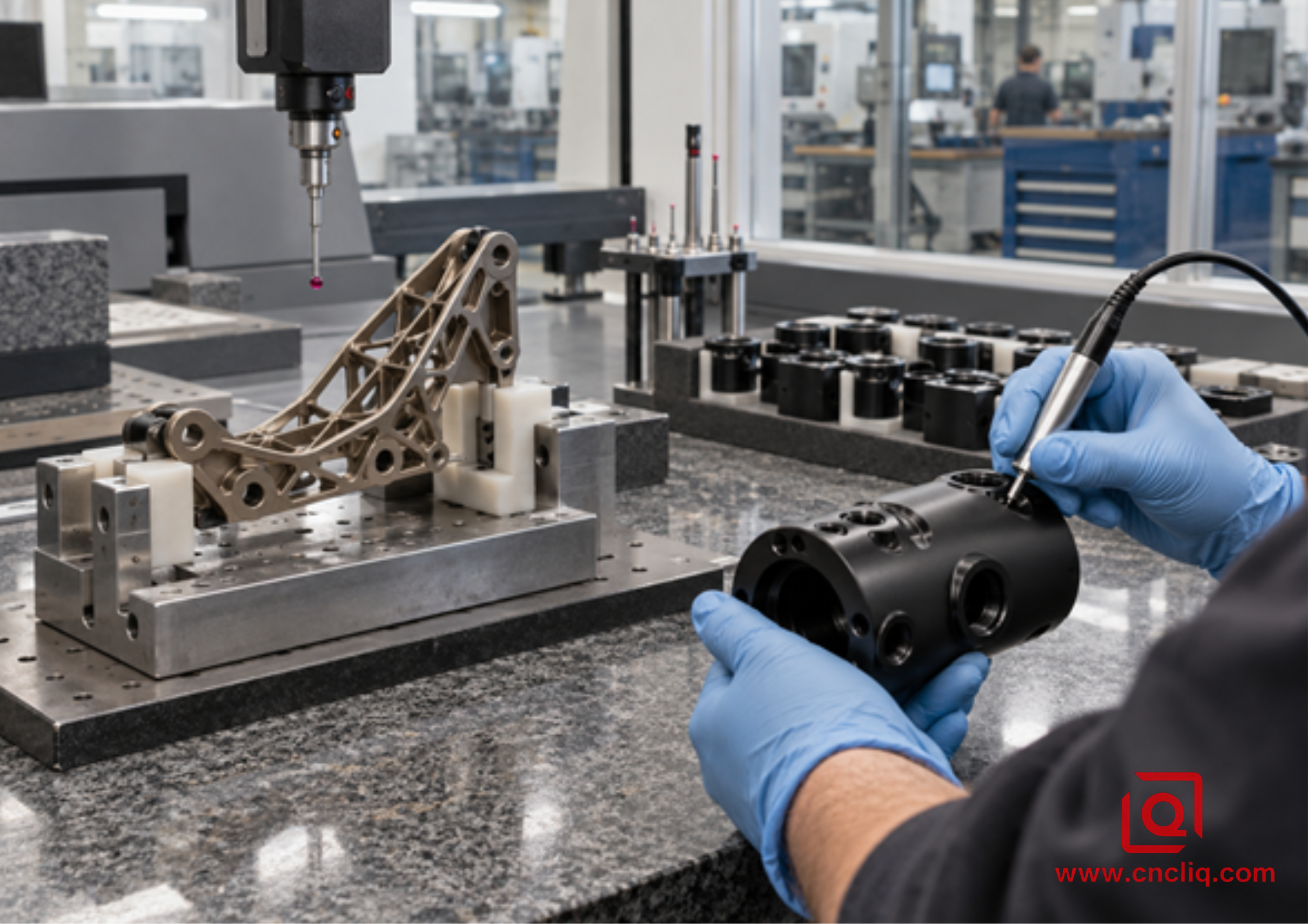
Quality image: coating-thickness and CMM inspection of distinct anodized components
The AAC specification guidance lists coating thickness, density, and seal integrity as distinct quality characteristics and points specifiers toward appropriate ASTM and ISO methods. That separation matters.A beautiful part can fail function, while a dimensionally correct part can still miss an agreed cosmetic window.
9. What to Send for a Fast, Reliable Quotation
A good RFQ lets an engineer see finishing risk at a glance. Include alloy and temper, CAD and 2D files, Type and Class, target film, color basis, texture, cosmetic and masked zones, rack contacts, final dimensions, reports, quantity, destination, and required date. A loose bracket may forgive one missing item. A matched housing with close fits may not.
For matched assemblies, also state whether components must be processed as a set and whether different alloys are present. If the acceptable appearance is difficult to describe, request sample coupons from the actual production stock. To discuss a new custom 6061 or 7075 project, send the drawings through Liqin’s contact page and ask for a machining-plus-anodizing DFM review.
FAQs
1. Will clear anodized 6061 and 7075 look the same?
Usually not. The word clear causes much of the confusion: it means no dye was added, not that the oxide is colorless. A 6061 part often stays silver or light gray, while the same nominal process can leave 7075 yellow, bronze, gray, or olive. For a cosmetic assembly, approve samples made from both production alloys.
2. Can black dye hide the difference between 6061 and 7075?
Black narrows the gap, but it cannot change the metal underneath. A 7075 component may still look warmer or less deep than its 6061 neighbor. Hold material lots, starting texture, film build, dye conditions, and sealing as steady as possible. If both alloys remain visible, approve a separate limit range for each.
3. Is 7075 unsuitable for Type III hardcoat anodizing?
No. Shops hardcoat 7075 whenever the strong substrate and wear-resistant surface justify the choice. The job simply needs a better planning discussion around film build, edge condition, masking, fatigue-sensitive areas, and natural color. Qualify the actual alloy and geometry. A generic black coupon does not represent every part.
4. How much should I compensate a bore for anodizing?
Begin with an estimate, not a universal allowance copied from an old job. For early DFM, treat about half of the film as outward growth; a coated bore may lose roughly one coating thickness in diameter. The true split depends on alloy and process. Obtain the finisher's data, then verify the fit on representative parts.
5. What is the best way to specify anodized color uniformity?
Write the color-acceptance method as carefully as the finish callout. State alloy, temper, lot rule, preparation, Type, Class, thickness, dye, seal, and cosmetic zones. Add a signed master with light and dark limits. If a colorimeter controls acceptance, define the color space, illuminant, geometry, reading locations, and numerical window. An email photograph is not a color standard.
Summary
For cosmetic work, 6061 is normally easier to keep consistent. Choose 7075 when the load case needs it, then plan for a different surface response. Stock, texture, pretreatment, electrical contact, bath control, film thickness, dye, and sealing all influence the final look. Keep fit criteria separate from color criteria. Trial both alloys. Give the supplier enough information to plan machining and anodizing together.
Contact Information
Company: Ningbo Liqin Industry Co., Ltd.Daily customer maintenance & after-sales support:service@shturl. zhuwanying@cncliq.com
New inquiry, quotation & order discussion:business@shturl. zhouli@chinaliqin.com
Hotline: +86 18757148656
Disclaimer
All technical articles, material specifications, machining recommendations, and surface treatment details published on this blog are for informational and reference purposes only. Please note that general blog insights do not replace signed technical agreements. Because custom parts vary by material heat numbers, machine calibrations, and specific tolerances, binding quality specs are governed solely by your approved CAD drawings, signed contracts, and formal quality plans.
All customer case studies featured on this blog have been thoroughly anonymized and sanitized. The performance metrics, manufacturing workflows, and imagery displayed serve solely to demonstrate our custom machining capabilities and do not represent a single universal standard for all orders.
Liqin Manufacturing Team
Built on 18 years of precision engineering experience, Ningbo Liqin Industry manufactures high-tolerance metal components for demanding global markets. We operate out of a 6,500 m² production hub equipped with over 150 machines, running 4-axis and 5-axis CNC machining, mill-turn machining, cold extrusion, and pressure die casting under one roof. This setup allows us to manage projects seamlessly, taking parts from initial CAD concepts directly to finalized shipments.
We handle quality control with zero compromise. We treat tight tolerances with the engineering discipline they require. Backed by ISO 9001, ISO 13485, and IATF 16949 certifications, our QA engineers run strict IPQC, FQC, and OQC checks on every single production batch. From CMM dimensional mapping and optical profiling to hardness and salt-spray testing, we validate your critical specs upfront—so you receive drop-in ready components with zero assembly headaches or costly line stoppages. On top of manufacturing, you can rely on us for two-hour response times on new RFQs, direct support for prototype sampling, and smooth export shipping across Europe, North America, Asia, and Oceania.
Welcome your inquiries and samples. Visit our website or contact us directly for a competitive quote!
