 English




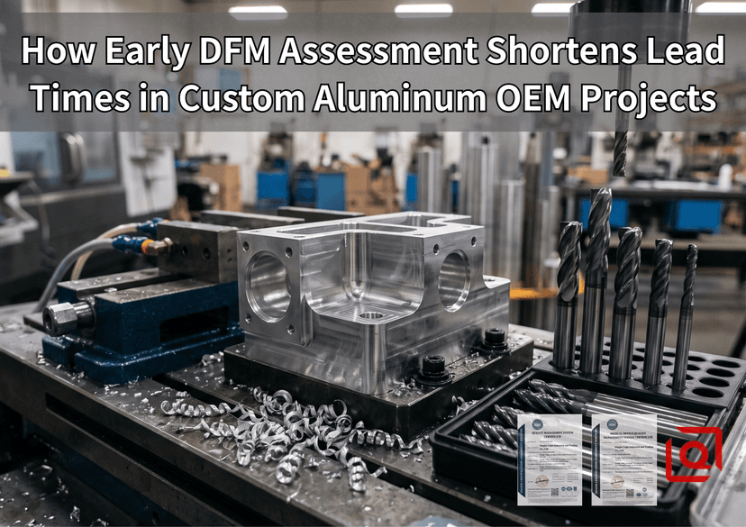
Forget polished marketing PDFs. Anyone who has ever run a 5-axis mill at 24,000 RPM knows that quote delays don't happen because of shipping logistics or raw material shortages. They happen because engineers submit STEP files with 0.5 mm internal corner radii on 45 mm deep pockets, expecting a 48-hour turnaround.
It won't happen. Not unless you want your cutter to chatter itself to death or snap an extra-long solid carbide end mill at $180 a pop.
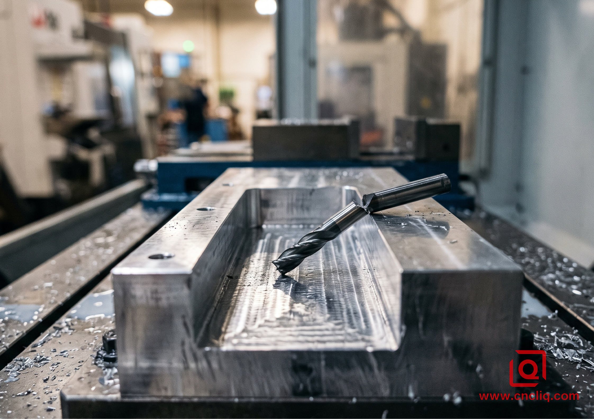
Front-loading Design for Manufacturability (DFM) during RFQ stages isn't a design formality—it's raw risk mitigation. In custom aluminum OEM projects, running a strict 2-hour DFM audit before locking in CAM toolpaths consistently strips 40% to 60% of lead time out of schedules. Here is how we diagnose, tweak, and execute on the factory floor.
Quick Reference: DFM Bottlenecks vs. Floor Optimizations
| Critical Feature | Unoptimized Engineering Spec | Floor Reality & Failure Mode | DFM Corrective Standard | Production Lead Time Impact |
| Pocket Depth-to-Width | L/D Ratio > 8:1 (e.g., 60 mm deep with R3 mm corner) | Tool deflection > 0.08 mm, severe chatter, cutter breakage | Adjust floor fillet to R ≥ 1.5× tool Ø; step-down roughing | Cuts CAM cycle time by 38%; eliminates custom tooling lead time |
| Thin Wall Geometry | Uniform wall thickness < 0.8 mm across 120 mm length | Resonance at High-Speed Machining; dimensional drift > ±0.06 mm | Tapered wall profile (≥ 1.2 mm base), sequence step-milling | Eliminates secondary bench straightening; saves 24 hours |
| Internal Thread Depth | Blind M4 × 0.7 tapped to 15 mm depth (3.75D) | Chip packing in AL 6061-T6, thread tap breakage | Limit full thread depth to ≤ 2.5D; relief undercut at bottom | Saves 12% machine down-time; eliminates spark EDM extraction |
| Anodizing Allowance | H7 tolerance (0/+0.015 mm) on raw machined bore | Hardcoat Anodizing (MIL-A-8625 Type III) adds 25 µm/side | Machine bore offset to +0.035/+0.050 mm pre-plate | 0% assembly fit rework; skips secondary reaming |
Key Takeaways
-
Zero Custom Tooling Delays: Standardizing internal cavity radii to match off-the-shelf carbide end mills avoids waiting 5–7 days for custom-ground form cutters.
-
Stable Tolerancing: Decoupling non-mating geometric features down to ISO 2768-m allows aggressive roughing feeds up to 6,000 mm/min without risking drift on critical ±0.008 mm bearing seats.
-
First-Pass Anodizing Fit: Accounting for Type III hardcoat growth directly in the CAM model eliminates post-plating line-boring or hand-scraping during assembly.
The Geometry Trap: Tool Aspect Ratios and High-Speed Milling
Look at a typical AL 7075-T651 bracket. The CAD looks sleek. But pushing a 6 mm 3-flute carbide end mill deeper than 5× its diameter into an enclosed cavity makes tool deflection a physical guarantee.
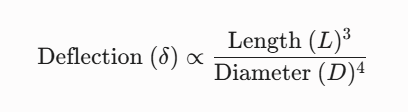
Triple overhang length, and deflection jumps by 27 times. At 18,000 RPM, that deflection translates to severe harmonics, bad surface finishes exceeding Ra 3.2 µm, and dimensional taper.
The Floor Fix:
-
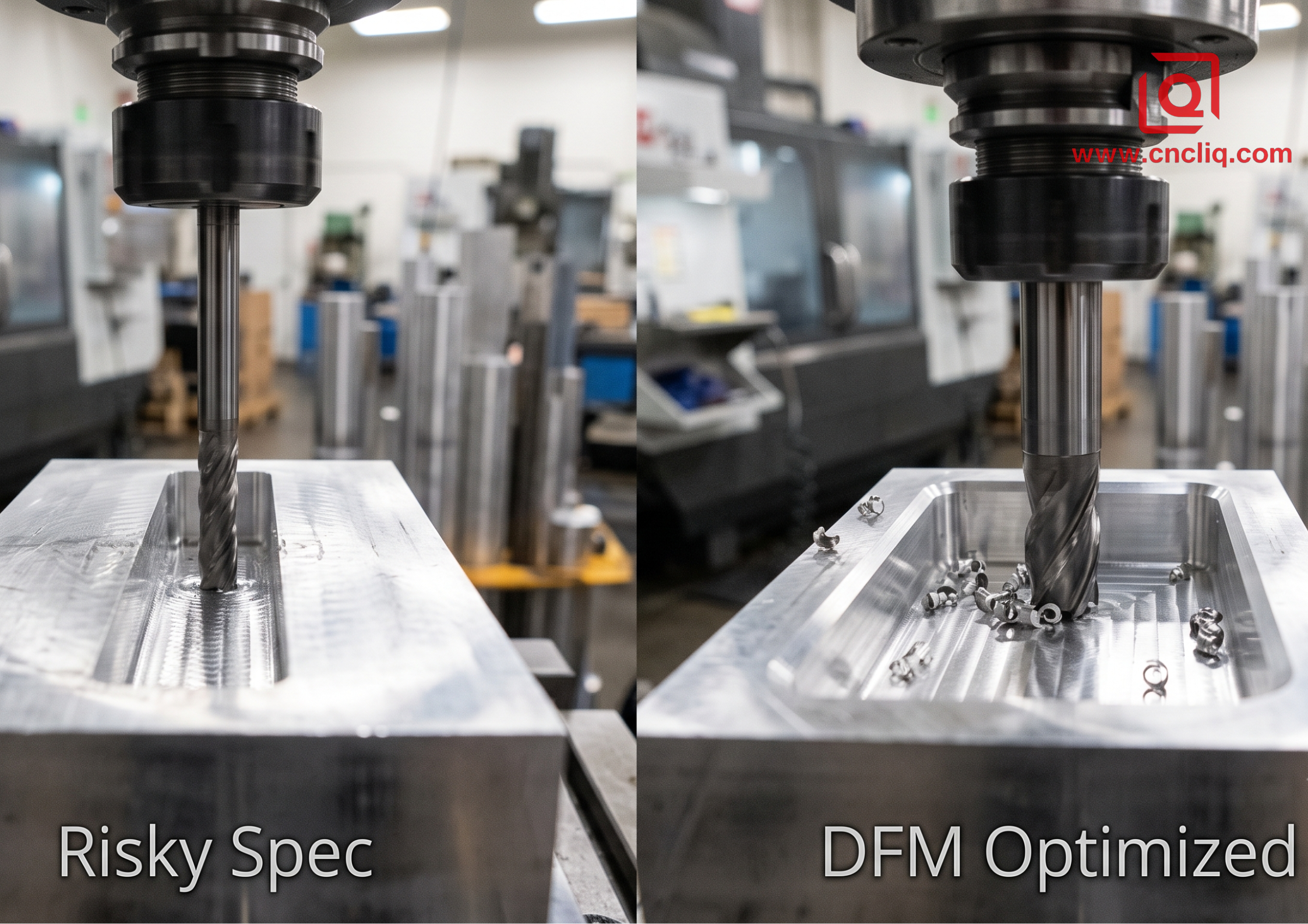
Open internal vertical corner radii from 3 mm to 4.5 mm. This lets a standard 8 mm tool clear corners without lingering at 100% radial engagement (which triggers chatter).
-
Keep pocket depth-to-tool-diameter ratios under 4:1 whenever possible.
-
If deep cavities are unavoidable, mandate a 1.5° wall draft angle. This lets cutter shanks clear top edges, preventing tool rub and work-hardening.
Modifying a batch of 150 UAV motor mounts this way boosted chip load per tooth from 0.03 mm to 0.09 mm. Cycle time dropped from 42 to 18 minutes per part.
Thin-Wall Resonance and Heat Treatment Deformation
Thin aluminum walls under 1.0 mm act like tuning forks when struck by cutters running at high speeds (Vc = 600 m/min).
During an AL 6061-T6 run of optical enclosures, leaving raw parts un-clamped on benches for just 3 hours post-roughing caused a 0.045 mm bow across 180 mm spans. Why? Internal residual stress relief. Machining a thin profile in one pass releases rolling stresses unevenly, ruining flat datum surfaces.
Floor Action Items:
-
Don't complete profiling in one setup. Rough side A, rough side B, let the block sit on racks for 2 to 4 hours to relieve stress, then execute finish passes.
-
Stair-step milling path: Machining wall heights in 5 mm incremental depth passes while backing up opposite sides with stock maintains rigidity.
-
Keep minimum wall thickness above 1.2 mm for features exceeding 50 mm in height, unless paying for custom vacuum fixtures or low-melting alloy support.
Blind Thread Tapping: The Unseen Schedule Killer
Blind holes tapped deeper than 2.5 times pitch diameter are production hazards. In AL 6061-T6, long continuous chips pack tightly at hole bottoms. Rigid taps hitting compressed chips at 1,500 RPM snap instantly.
Extracting broken M3 spiral-flute taps out of $400 housings via sinker EDM takes 3 hours and adds $80 labor—assuming threads aren't ruined.
Execution Directive:
-
Change blind tapped holes to thread milling where hole diameter exceeds M5.
-
For smaller threads (M2 to M4), restrict full-form thread depth to 2.0D max.
-
Add 1.2 mm drill point clearance oversize beyond full thread depth so chips have neutral collection pockets.
Surface Finishing Offset: Accounting for Anodizing Build-up
Never send drawings specifying H7 (+0.015/-0 mm) bearing bore tolerances alongside "Anodize per MIL-A-8625 Type III Hardcoat" callouts without explicit offset notes.
Type III hardcoat penetrates substrates by 50% and builds up on surfaces by 50%. A specified 30 µm coating thickness means internal bore diameters shrink by 30 µm (15 µm per wall). Machining bores to nominal target 28.000 mm yields post-anodize measurements of 27.970 mm. Bearings won't fit.
Floor Process:
-
Annotate whether tolerances apply BEFORE or AFTER surface treatment.
-
For Type III Anodizing, offset CAM nominal boring toolpaths by +0.030 mm on internal diameters and -0.030 mm on shafts.
-
For Chromate Conversion Coating (MIL-DTL-5541 Class 1A), dimensional change is negligible (< 1 µm)—no CAM compensation required.
Data Verification and Standards Compliance
Floor engineering procedures align with international benchmarks to guarantee zero-rework handoffs:
-
GD&T Tolerancing: ASME Y14.5-2018 (True Position and Composite Profile limits)
-
General Machining: ISO 2768-m (Medium grade for non-critical geometry)
-
Thread Verification: ASME B1.1 Class 2B/3B Go/No-Go plug gauge certification
-
Anodizing Thickness: ISO 2360 eddy-current measurement protocol
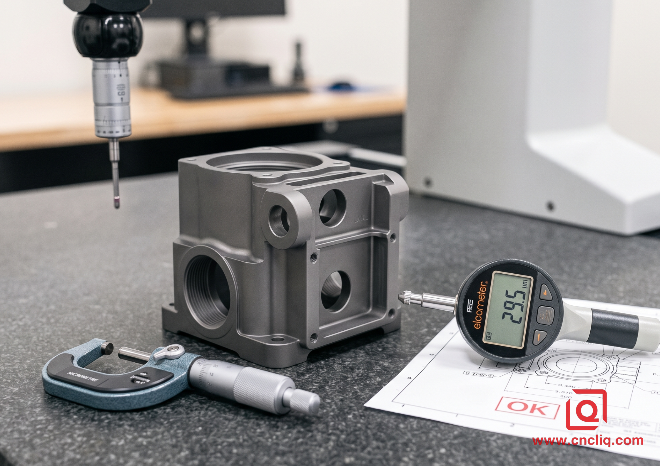
Data Source: Internal CNC Machining Log & DFM Archives (Project Series #AL-OEM-2025/2026, Sample Size: 3,400+ parts).
FAQs
Q1: Why do complex internal corner profiles drastically increase machining lead times?
A: When an end mill traverses a tight internal right-angle corner, it suddenly transitions from cutting along a straight path to engaging metal across a much wider contact area. This sudden spike in radial tool engagement creates immense resistance, forcing the machine operator to throttle down the feed rate significantly to avoid snapping the tool. By slightly rounding these inner corners to allow room for the cutter to sweep smoothly around the curvature, the spindle can maintain a high, steady speed without halting or causing tool chatter.
Q2: How does heat generation during aluminum machining cause unexpected dimension failure?
A: Aluminum transfers heat rapidly. When heavy roughing cuts frictionally heat the workpiece, the localized metal expands while locked under vise pressure. Once the finished component is unclamped, taken off the machine bed, and cooled down to room ambient temperature, the metal contracts. This thermal shrinkage pulls tight-tolerance bore diameters and mounting faces out of alignment. Allowing components a dedicated stabilization period between roughing and finishing passes prevents this thermal movement from corrupting final measurements.
Q3: Why is thread milling preferred over traditional tapping for deep blind holes?
A: Taps function by pushing through material in a continuous cutting motion, which forces long, fibrous aluminum chips down into the bottom of a blind hole. As these chips become densely compacted, they bind the tool and frequently snap the tap inside the workpiece. A thread mill, by contrast, uses a smaller diameter cutter rotating at high speeds while spiraling around the hole circumference, breaking chips into tiny fragments that are easily blown out by coolant air blasts, virtually eliminating the risk of tool breakage.
Q4: Why shouldn't raw aluminum parts be anodized immediately after machining?
A: Freshly machined aluminum surfaces retain cutting fluid residues, embedded micro-particles, and a uneven natural oxide film. If dipped straight into an anodizing bath, these surface contaminants disrupt the electrochemical process, causing blotchy discoloration, chalking, or uneven coating growth. Parts must first undergo a rigorous chemical degreasing, etching, and desmutting sequence to strip away surface impurities and present a clean, chemically uniform aluminum substrate for perfect oxide layer adhesion.
Q5: What is the main cause of thin aluminum plates bowing or warping after being released from a vise?
A: Raw aluminum bar stock holds significant internal residual stresses formed during the mill rolling and extrusion processes. When heavy material is carved away from only one side of the plate, these internal forces become unbalanced, causing the metal to physically spring and bow as soon as the vise jaws release their clamp. To keep thin plates flat, operators must balance metal removal symmetrically from both sides and allow the material to rest and relieve stress before taking final finishing passes.
Ready to Cut 50% Out of Production Lead Times?
Stop letting unoptimized CAD drawings stall quotation cycles. Send 2D PDF and 3D STEP files to our floor engineering team. We deliver complete 3D DFM reports and firm, production-ready quotes within 2 hours.
Contact Information
Disclaimer
Liqin Manufacturing Team
We are Ningbo Liqin Industrial & Trading Co., Ltd.,a professional manufacturer with over 18 years of experience in high-precision custom metal parts. We specialize in CNC machining, forging, die casting, and cold extrusion processes, serving industries such as automotive, medical, aerospace, electronics, and more. Our factory covers an area of 6,500 square meters and is equipped with 150+ advanced machines, including:
- CNC machining centers (4-axis, 5-axis)
- CNC lathes and turning-milling complexes
- Cold extrusion equipment (250T–650T)
- Die casting machines
We adhere to ISO9001, ISO13485: 2016, and IATF16949: 2016 standards, implementing end-to-end quality management: In-process quality control (IPQC), final quality control (FQC), outgoing quality control (OQC). CMM, projectors, hardness testers, and salt spray test equipment. Our products are exported to North America, Europe, Asia, and Oceania. We offer:
- One-stop service from design to delivery
- Quick response within 2 hours for quotes and technical support
- Custom solutions based on your drawings or samples
Welcome your inquiries and samples. Visit our website or contact us directly for a competitive quote!
