 English




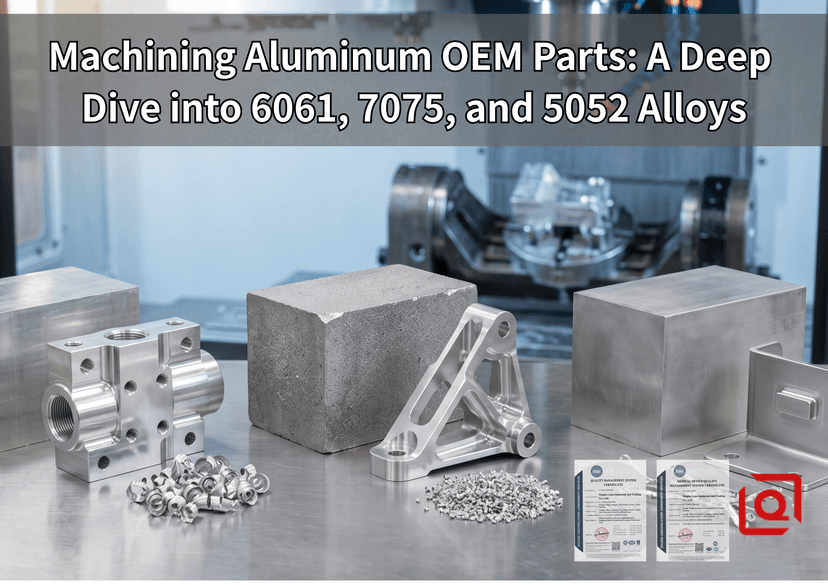
If you run an engineering desk or handle custom component procurement, you have seen this pattern: a print calls out aluminum without specifying the temper, or worse, specifies an aerospace alloy for an enclosure that simply needs clean sheet bending and salt-spray resistance. Selecting raw stock is never just about yield strength numbers on a material data sheet. On the shop floor, alloy chemistry dictates your tooling wear, your feed rates, whether your chips break into crisp curls or wrap around your spindle like bird nests, and how much dimensional drift you fight after releasing the vise jaws.
Let’s bypass the textbook generalities. In everyday OEM custom part milling, 6061, 7075, and 5052 account for almost 85% of our shop traveler sheets. Put them on the table, and they cut, take an anodized finish, and hold down in fixtures quite differently under a carbide tool.
1. Quick Technical Comparison & Material Standards
Before discussing shop-floor behavior, let's map these three workhorses against manufacturing baselines and testing protocols.
| Engineering Parameter / Standard | 6061-T6 / T651 | 7075-T6 / T651 | 5052-H32 |
| Primary Industry Standards | ASTM B221, AMS 4027, MIL-STD-1537 | ASTM B209, AMS 4045, AMS-QQ-A-225/9 | ASTM B209, AMS 4016, QQ-A-250/8 |
| Major Alloying Elements | 0.8–1.2% Mg, 0.4–0.8% Si, 0.15–0.4% Cu | 5.1–6.1% Zn, 2.1–2.9% Mg, 1.2–2.0% Cu | 2.2–2.8% Mg, 0.15–0.35% Cr, <0.25% Si |
| Tensile Strength (Yield / Ultimate) | 276 MPa / 310 MPa | 503 MPa / 572 MPa | 193 MPa / 228 MPa |
| Brinell Hardness (HBW, 500kg, 10mm) | 95 HBW | 150 HBW | 60 HBW |
| Machinability Index (2011-T3 = 100) | 80% (Crisp chip fracture) | 70% (Very rigid, low edge buildup) | 40% (Gummy, long stringy chips) |
| Recommended Surface Speed ($V_c$) | 350 – 750 m/min | 250 – 600 m/min | 200 – 450 m/min |
| Standard Anodizing Suitability | Excellent for Type II & Type III Hardcoat | Good for Type II; yields bronze-grey tone under Type III | Excellent for Clear Anodize; poor for deep dye uniformity |
| Cold Formability / Bending | Moderate (min bend radius 2.5t–3t) | Poor (susceptible to micro-cracking) | Outstanding (min bend radius 1t–1.5t) |
2. Alloy Profiles: Machine Performance, Tooling, and Chip Dynamics
     6061-T651                  7075-T651                   5052-H32
┌──────────────────┐       ┌──────────────────┐       ┌──────────────────┐
│  All-Rounder     │       │  Rigid / Aero    │       │  Sheet / Marine  │
│  Balanced Speed  │       │  High Shear Load │       │  Gummy Cut       │
│  Crisp Chips     │       │  Short Granular  │       │  Waxy Swarf      │
└────────┬─────────┘       └────────┬─────────┘       └────────┬─────────┘
         │                          │                          │
   General CNC            High-Stress Brackets         Formed Enclosures
   Optics / Manifolds     Spars & Gear Mounts          Brackets & Chassis
6061-T651: The OEM Workhorse
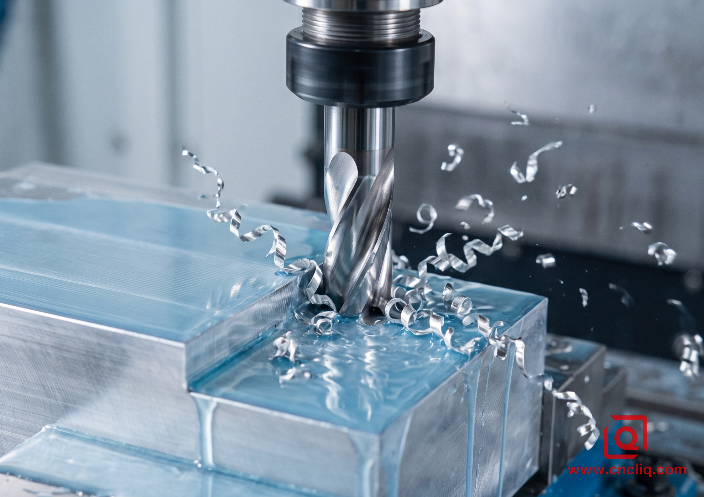
6061 is the standard default for good reason. Silicon and magnesium combine into magnesium silicide (Mg₂Si), giving it balanced mechanical properties, dependable chip fracture, and moderate tool wear.
Cutting Parameters & Setup Rules:
- Roughing: Run a 3-flute, bright micro-grain solid carbide cutter at 40° to 45° helix for full-depth slotting or profiling. Feed it aggressively up to 500 m/min surface speed, dialing chip load around 0.12 mm/tooth.
- Coolant: Keep soluble trim at 8% to 10% mix. Flooding the tool path stops built-up edge cold before it smears your final wall passes.
- Fixturing & Warpage: Even with pre-stretched 6061-T651 stock, deep pocketing will unleash unbalanced skin tension. Face-mill both sides clean to equalize residual load before you touch your finishing tools or lock in tight datum holes.
7075-T651: High Shear Strength, Low BUE, High Internal Stress
7075 swaps silicon for zinc, magnesium, and copper. It cuts cleanly—the chips shatter into small commas, leaving near-mirror milled surfaces without edge galling. However, that cutting satisfaction comes with mechanical resistance and internal stress.
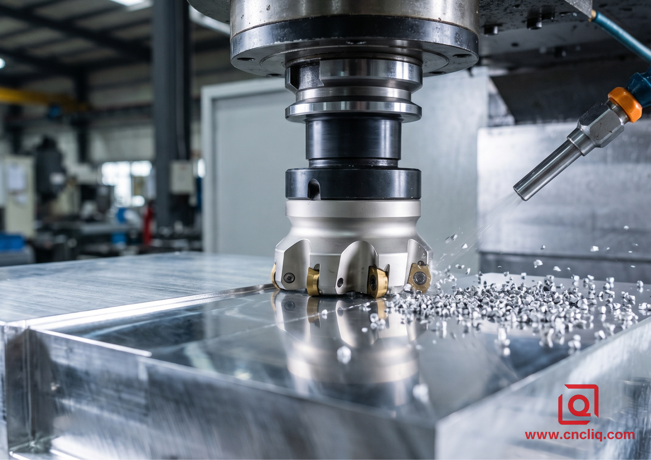
Face Milling 7075-T651:
Tool: 50mm Face Mill (PCD / Polished Carbide Inserts)
Speed: 450 m/min  |  Feed: 0.15 mm/tooth  |  Stepover: 70%  |  Air/Mist Blast
Result: Minimal edge tearing, high dimensional stability on stout walls.
Cutting Parameters & Strategies:
-
Cutter Selection: Use positive rake inserts with polished flutes or Diamond-Like Carbon (DLC) coatings to handle higher cutting forces without thermal loading.
-
Tool Push-off: At 150 HBW, this alloy fights long-reach cutters hard. On deep cavity walls, pull your stepover (ae) back to 15–20% of tool diameter. That keeps tool flex in check and nails your ±0.01 mm perpendicularity callout.
-
Stress Traps: Hogging out 70% of uneven billet volume invites parts to banana. Always order T651 stretched plate per AMS 4045, then run rough-settle-finish steps so heat and trapped tensions bleed off prior to shaving final tolerances on tight datums.
5052-H32: Marine-Grade Ductility and Gummy Machining
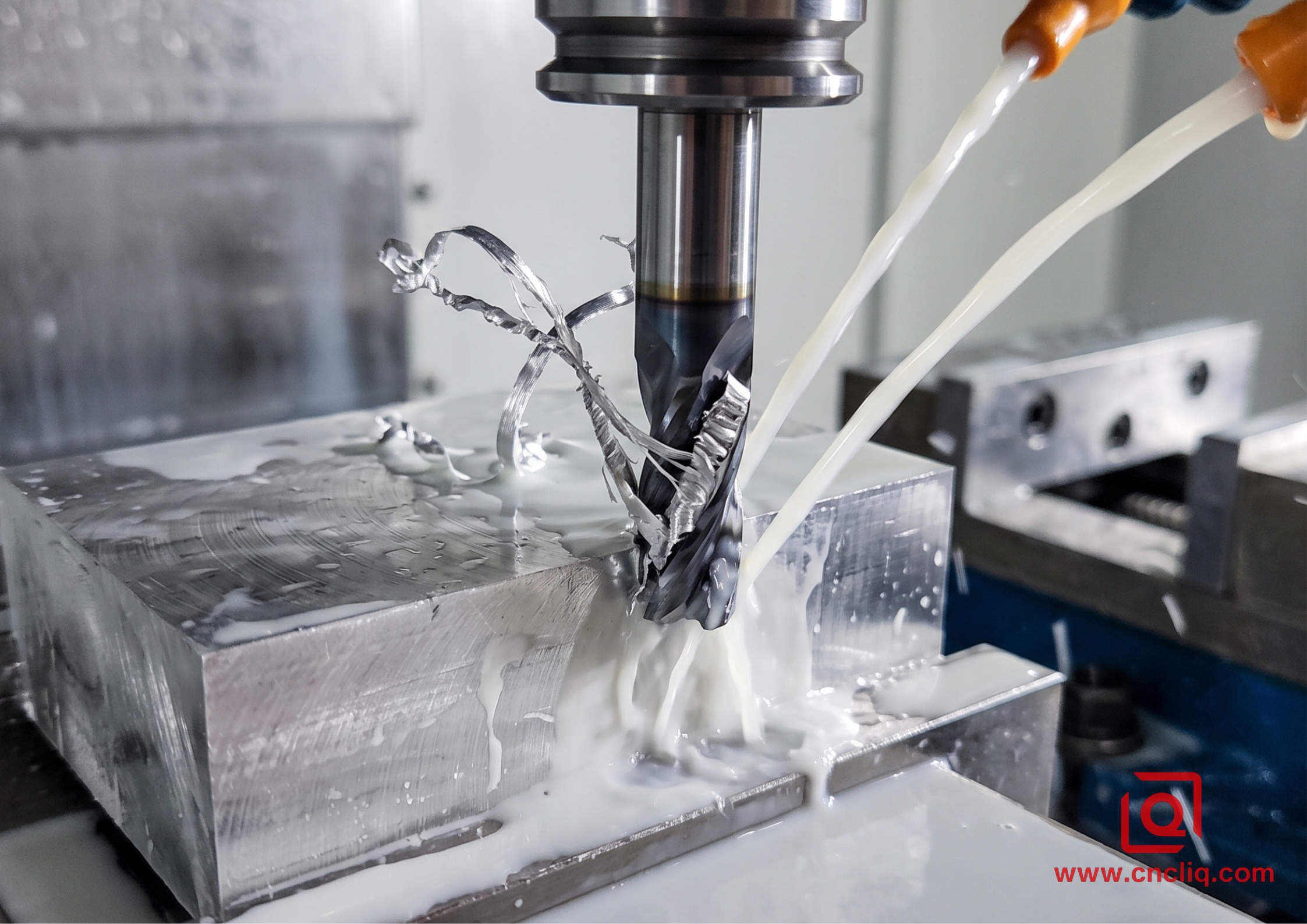
5052 is non-heat-treatable, relying on magnesium solution hardening and cold working. It excels at sheet metal fabrication, deep drawing, and salt-spray resistance. When customers request milling features on 5052 billets or bent bracket bosses, cutting mechanics change completely.
Cutting Parameters & Strategies:
-
The Gummy Chip Challenge: 5052 lacks copper and silicon precipitations. Chips smear and weld onto tool cutting edges.
-
Tooling: Switch down to single or 2-flute mirror-ground end mills. Push the chip load up (fz = 0.15 to 0.20 mm/tooth) so the keen edge bites clean underneath the shear plane instead of smearing and work-hardening the stock.
-
Lubrication: Flood the cut with focused high-pressure coolant (at least 15 bar) or run fatty-alcohol MQL to clear gummy ribbons from deep cavities and keep the flute gullets from packing.
3. Real-World Field Case: Hydraulic Test Manifold
A customer supplying fluid power components ordered custom test manifolds with 12 intersecting cross-bores, flat seal faces, and thread ports.
Design Requirements:
- Flatness: 0.015 mm over 200 mm
- Bore Diameters: 18.00 mm (+0.018/-0.000 mm)
- Operating Pressure: 160 bar
- Finish: MIL-A-8625 Type II Clear Anodize
Production Routing:
[Saw Cut 6061-T651] -> [Face Top/Bottom (0.5mm stock)] -> [Rough Cavities]
        │
        ▼
[Rest 12h for Stress Dissipation] -> [Semi-Finish Pockets] -> [Deep Drilling]
        │
        ▼
[High-Pressure Flush 30 bar] -> [Final Ream Bores] -> [Thread Milling]
        │
        ▼
[CMM Inspection] -> [Type II Anodize with Bore Masking] -> [Final Pack]
           HYDRAULIC MANIFOLD INTERNAL BORE CROSS-SECTION
 ┌──────────────────────────────────────────────────────────────┐
 │                      O-Ring Seal Face (Ra 0.4)               │
 │                 ▼▼▼▼▼▼▼▼▼▼▼▼▼▼▼▼▼▼▼▼▼▼▼▼▼▼▼                  │
 │      ┌──┐                                        ┌──┐        │
 │      │  │◄── Threaded Port (UNF 7/16-20)         │  │        │
 │      │  │                                        │  │        │
 │   ┌──┘  └──┐                                  ┌──┘  └──┐     │
 │   │        │                                  │        │     │
 │   │  Bore  │════════ Intersecting ════════════│  Bore  │     │
 │   │   #1   │       Cross-Drill (Ø6.5mm)       │   #2   │     │
 │   │        │══════════════════════════════════│        │     │
 │   └──┐  ┌──┘                                  └──┐  ┌──┘     │
 │      │  │                                        │  │        │
 │      └──┘                                        └──┘        │
 │                                                              │
 └──────────────────────────────────────────────────────────────┘
Machining Execution & Observations:
-
Material Confirmation: We picked 6061-T651 stock under ASTM B221; full MTRs checked out with a 285 MPa yield and 14% elongation.
-
Deformation Control: First test cuts on extruded bar warped the seal face by 0.04 mm right after popping it out of standard 6-inch vise jaws. To solve the warp, we shifted to pre-stretched T651 plate stock, roughed both faces while holding 0.5 mm finish stock, dialed hydraulic vise pressure down from 4.5 bar to 1.8 bar using contoured soft jaws, and let the billet rest for 12 hours. For the final skin cut, we ran an 80 mm face mill tipped with mirror-polished PCD inserts (Vc = 850 m/min, fz = 0.08 mm/tooth) across the sealing deck. The surface settled flat at 0.008 mm.
-
Deep Cross-Drill Deburring: Intersecting cross-holes at 90° created heavy entry/exit burrs inside the 18.00 mm bore. We avoided hand deburring scrapers, which cause micro-scratches on internal fluid seals. Instead, we used a reverse-chamfer micro-tool on the 5-axis center at 6,000 RPM, followed by 30-bar high-pressure coolant flushing to guarantee zero trapped aluminum slivers.
-
Anodizing Pre-Compensation: Because the part required MIL-A-8625 Type II Class 1 clear anodize, the coating adds approximately 0.005–0.010 mm total diametrical buildup on bore walls. We pre-machined internal precision ports to 18.012 mm, allowing the coating to build back precisely into the customer's +0.018/-0.000 mm design window.
4. OEM Engineering Cheat Sheet: Selecting the Right Stock
                              OEM SELECTION FLOW
                                      │
               Is high structural strength / fatigue life the top priority?
                                ├──► YES ──► Select 7075-T651 (Specify AMS 4045)
                                │
               Is severe sheet bending or marine salt-spray exposure needed?
                                ├──► YES ──► Select 5052-H32 (Specify ASTM B209)
                                │
               Need balanced CNC machining, weldability, and crisp anodizing?
                                └──► YES ──► Select 6061-T651 (The OEM Baseline)
-
Run 6061-T651 as the standard stock for motor housings, sensor mounts, pneumatic manifolds, and automation framing. It cuts clean, takes TIG passes without blowing out, and builds a tough hard-anodize layer for rub wear.
- Spec 7075-T651 for high-load pivot links, airframe hardpoints, steering knuckles, and heavy-duty assembly fixtures. Just ensure your vendor steps toolpaths evenly to tame trapped core tension.
-
Reserve 5052-H32 for electronics enclosures, sea-going instrument lids, reservoirs, and bent-and-milled weld assemblies. It wins whenever salt-spray survival and sharp form radii outweigh rapid cycle times on the spindle.
FAQs
Q1: Why call out 6061-T651 cast/rolled plate over basic extruded 6061-T6 bar for precision housings?
Extruded 6061-T6 traps heavy, uneven quench tension right from the die press. Hog out deep pockets or clear past 50% raw material, and that trapped stress springs loose—warping your parts 0.05 mm to 0.20 mm the second vises loosen. Specifying the T651 temper means mills pull the stock through 1.5% to 3.0% mechanical stretching post-solution treat. That pulls the internal stress straight out, locking flatness well within 0.010 mm across wide faces.
Q2: How do you adjust CNC machining tolerances to account for Type 2 vs. Type 3 anodizing thickness?
Anodize runs on a straightforward rule of thumb: the film digs inward halfway into the raw stock while pushing outward the rest of the way. When running typical MIL-A-8625 Type 2 sulfuric tanks, this outward buildup deposits a thin shell across every exposed wall, shrinking internal bore diameters by about 0.010 mm to 0.016 mm. Switch gears to a heavy-duty Type 3 Hardcoat, and that hole closure swells up to 0.050 mm. We dial this in at the CAM station by opening up dowel locations, bearing fits, and tapped threads beforehand. That deliberate overcutting offsets the plating buildup, ensuring features hit nominal right out of the dip.
Q3: Can 7075-T6 be welded reliably if an OEM assembly requires both CNC milling and frame welding?
Because 7075 packs high shear resistance (with yield strength topping 503 MPa), long-reach cutters easily flex and push away from deep cavity walls. When carving thin structural ribs taller than an 8:1 aspect ratio, never attempt a full-depth finish pass. Hog out the pocket volume with dynamic trochoidal clearing, leaving just a skim of stock along the ribs. For the finish contour, step down the sidewall with an anti-harmonic carbide tool; take feather-light radial cuts along the rib to knock out resonance and hold true vertical within 0.010 mm.
Q4: Why does 5052-H32 clog cutting tools so quickly, and how do machinists prevent built-up edge (BUE)?
5052 runs exceptionally soft and gummy, without the brittle silicon phases needed to snap stringy ribbons into clean chips. Heat buildup makes the ductile stock smear and gall against the cutting flute, loading up the tool until small end mills snap. To keep chips flowing clear, machinists toss standard multi-flute cutters in favor of mirror-polished 1-flute or 2-flute carbide end mills with wide gullets, step up the feed to take a heavier chip load of 0.15 mm/tooth, and blast high-pressure coolant right at the shear point.
Q5: What documentation should I demand from an aluminum OEM supplier to verify genuine raw stock?
Ask for a batch-matched Mill Test Report (MTR) tied to the raw bar or billet heat number before running any spindles. A genuine material test report backs the melt chemistry against ASTM B209/B221, along with actual tensile pull figures for yield strength, ultimate load, and percent elongation. For aero or defense contracts, always demand complete lot traceability meeting AMS-QQ-A specs, paired with AMS-STD-2154 ultrasonic inspection to confirm the billet core has zero subsurface porosity or voids.
Summary
Matching the right aluminum grade to custom OEM hardware boils down to pairing raw stock physics with actual machining dynamics. 6061 remains the go-to workhorse for tight-tolerance milling and clean anodized finishes, whereas 7075 delivers raw load capacity for flight-critical frames despite its heavy locked-in residual stress. On the flip side, 5052 rules sheet metal bending and saltwater use, though its gummy chip flow requires razor-sharp cutters. Accounting for these raw behaviors through rigid fixturing, thermal stress-relief runs, and anodize build-up offsets guarantees parts hit print specs consistently without post-machining warp.
Contact Information
Disclaimer
All technical articles, material specifications, machining recommendations, and surface treatment details published on this blog are for informational and reference purposes only. Please note that general blog insights do not replace signed technical agreements. Because custom parts vary by material heat numbers, machine calibrations, and specific tolerances, binding quality specs are governed solely by your approved CAD drawings, signed contracts, and formal quality plans.
All customer case studies featured on this blog have been thoroughly anonymized and sanitized. The performance metrics, manufacturing workflows, and imagery displayed serve solely to demonstrate our custom machining capabilities and do not represent a single universal standard for all orders.
Liqin Manufacturing Team
Built on 18 years of precision engineering experience, Ningbo Liqin Industry manufactures high-tolerance metal components for demanding global markets. We operate out of a 6,500 m² production hub equipped with over 150 machines, running 4-axis and 5-axis CNC machining, mill-turn machining, cold extrusion, and pressure die casting under one roof. This setup allows us to manage projects seamlessly, taking parts from initial CAD concepts directly to finalized shipments.
We handle quality control with zero compromise. We treat tight tolerances with the engineering discipline they require. Backed by ISO 9001, ISO 13485, and IATF 16949 certifications, our QA engineers run strict IPQC, FQC, and OQC checks on every single production batch. From CMM dimensional mapping and optical profiling to hardness and salt-spray testing, we validate your critical specs upfront—so you receive drop-in ready components with zero assembly headaches or costly line stoppages. On top of manufacturing, you can rely on us for two-hour response times on new RFQs, direct support for prototype sampling, and smooth export shipping across Europe, North America, Asia, and Oceania.
Welcome your inquiries and samples. Visit our website or contact us directly for a competitive quote!
