 English




Field Notes & Shop Rules
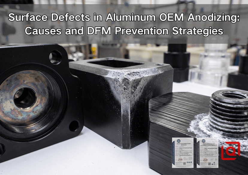
The Pretreatment Trap: Better than 70% of anodizing surface scrap traces back to the CNC setup—alkaline bath etching (50g/L NaOH at 55℃) pulls tool chatter and micro-tears into plain view instead of hiding them.
Alloy-Specific Current Scaling: Swap a run from 6061-T6 to zinc-rich 7075-T6 without trimming voltage or dialing in amperage (1.5 A/dm² vs 2.2 A/dm²), and you’ll fry the edges during MIL-A-8625 Type III hardcoat.
Dimensional Growth Math: Oxide layer buildup goes both ways—half expands outward. A 20 μm Type II coat adds 10 μm per wall, which blows right through Class 2B/6H thread pitch limits if you don't offset CAD geometry upstream.
The Anodizer’s Dilemma: When Machining Flaws Become Surface Disasters
A batch of 350 pump housings machined from 6061-T6 extruded stock hits the inspection bench after MIL-A-8625 Type II Class 2 black anodizing. Under 5000-Lux inspection lighting, an unsightly, mottled iridescent pattern runs along the bored cavities, accompanied by white chalky blooms haloing the internal M4×0.7 blind threads. The anodizing shop blames the machine shop’s coolant residue and heat-lot segregation. The machine shop blames bath contamination and improper sealing.
This blame game bleeds OEM budgets dry with scrapped stock and blown line schedules. Anodizing isn’t some spray-on skin—it never just sits on the metal like powder coat or electroplating. Instead, it converts the aluminum itself into an integrated lattice of hexagonal Al2O3 cells. Leave a smeared, work-hardened layer on your mill, mix 6061 stock from two batches with mismatched silicon phases, or forget vent holes on deep cavities, and that bath will brutalize your parts with zero pity.
Forensic Breakdown of 4 Fatal OEM Anodizing Defects
  +-----------------------------------------------------------------------+
  |                   ANODIZING LAYER GROWTH STRUCTURE                   |
  |                                                                       |
  |  Original Surface Line -- -- -- -- -- -- -- -- -- -- -- -- -- -- --   |
  |                            ^                     |                    |
  |                            | 50% Penetration     | 50% Outward        |
  |                            v                     v Growth             |
  |  ===================================================================  |
  |  ||  Barrier Layer  ||  Hexagonal Oxide Cells  || Film Thickness (t)  |
  |  ===================================================================  |
  |  Aluminum Base Metal Substrate                                        |
  +-----------------------------------------------------------------------+
1. Color Shift and Mottled Blotching
Variations in dye absorption occur when pore diameters fluctuate across the same rack. In sulfuric acid anodizing (180-200g/L H₂SO₄), pore cell morphology is strictly governed by bath temperature (19-21℃) and dissolved aluminum content (12-18 g/L).
A mere ±1.5℃ temperature swing shifts pore diameters from 12 nm to over 18 nm. Dip those parts in organic black dye (Sanodal Black MLW at 8 g/L, pH 5.5, 60℃), and wider pores suck up dye molecules twice as fast—leaving dark splotches next to faded gray zones on bottom-racked parts.
Worse yet, racking 6061-T6 (loaded with Mg₂Si precipitates) alongside 7075-T6 (high Zn/Mg phases) on one titanium tree throws current distribution way off. The lower-resistance 7075 hogs the amperage, starving your 6061 components.
2. Thermal Burning and Edge Dissolution
During MIL-A-8625 Type III Hardcoating (0–2℃, 160 g/L H₂SO₄, 3.2–3.8 A/dm²), exothermic heat builds up fast right at the oxidation boundary.
If air agitation fails to sweep the bath at 0.45 m/s or better around high-current hot spots—like sharp outside corners under R0.4 mm—local electrolyte temps jump past 35℃. Acid dissolution outpaces coat formation in a flash. That triggers severe burning: you get soft, powdery, pitted crusts, or totally washed-out corner profiles where the bare metal just melts into the tank.
3. Shadowing and Amplified Machining Chatter
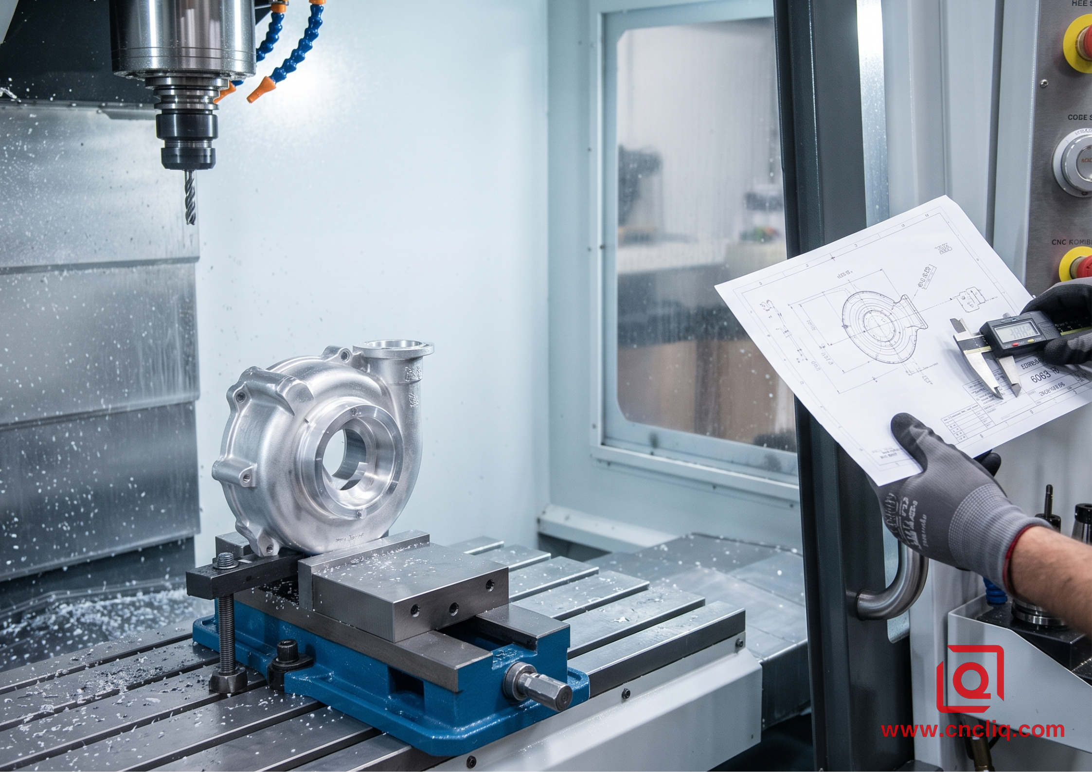
Engineers often assume that a 5-minute immersion in a caustic etching tank (50 g/L NaOH, 55℃, 2.5% dissolved Al) will melt away minor milling marks. It does the exact opposite.
Caustic soda attacks aluminum along grain boundaries and areas of high localized strain. If a dull 3-flute carbide endmill (vc > 300 m/min, feed per tooth fz < 0.02 mm) smearing the metal surface rather than shearing it cleanly, it creates a micro-strained surface layer. The NaOH bath etches the work-hardened micro-grooves faster than the stress-free substrate, transforming subtle Ra 0.8μm cutter chatter into severe Ra 3.2μm visual banding post-anodizing.
4. Post-Seal Acid Bleed-Out and Corrosion Blooming
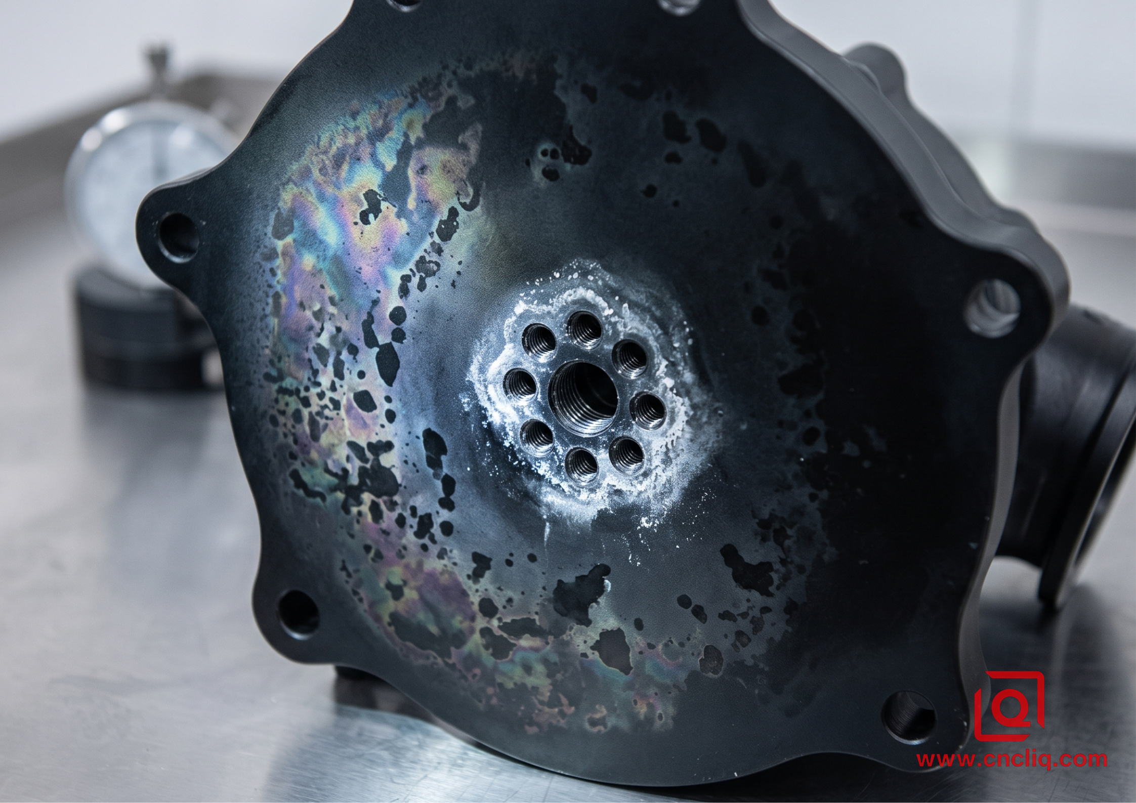
Blind tapped holes (M3–M6) and press-fit pin bores act as nasty acid traps for 180 g/L sulfuric electrolyte.
When post-anodize rinsing uses stagnant tap water instead of counter-current ultrasonic spray tanks over 40℃, capillary action seals residual acid tight inside those blind pockets. Once parts hit the hot nickel acetate seal bath (95℃, 2 g/L, pH 5.6), that trapped bath liquid expands and boils out over the threads. It kills the nickel seal locally, reacts with ambient humidity over 48 hours, and spews out a chalky, white aluminum sulfate bloom that eats away at mating screws.
Technical Comparison of Anodizing Defect Profiles
| Defect Manifestation | Root Cause Mechanism | Critical Process Parameter Exceeded | DFM & Shop-Floor Corrective Action |
| Pitted "Burning" on Sharp Edges | Localized thermal runaway during Type III hardcoat due to current concentration. | Current density > 3.5 A/dm²; Air agitation < 0.4 m/s. | Break all sharp crests to R≥ 0.8 mm; ramp up current over 8 minutes. |
| White Chalky Thread Blooming | Trapped H₂SO₄ boiling out during hot nickel acetate seal. | Blind hole depth > 3×Diameter; Rinse tank total dissolved solids > 450 ppm. | Mandate cross-drilled relief ports or force ultrasonic DI water rinse (> 50℃). |
| Ghost Tooling Lines / Banding | Caustic etch preferentially attacking work-hardened, smeared surface grain boundaries. | Milling feed rate fz < 0.02 mm; NaOH etch time > 6 mins. | Replace dull endmills; replace heavy chemical etching with #150 glass bead blasting (0.35MPa). |
| Color Mismatch Across Lot | Pore cell diameter variance caused by bath temperature drift or mixed metal heat-lots. | Tank temperature drift >±1.5℃; Racking mixed 6061 and 7075 alloys. | Enforce strict lot segregation; calibrate bath chillers to ±0.5℃; standardize dye tank pH to 5.5 ±0.2. |
DFM Rules for Machining Engineers Prior to Anodizing
                   CORRECT VS INCORRECT CORNER DFM

         INCORRECT (Sharp Corner)                CORRECT (Radiused Corner)

         High Current Density Peak                Uniform Field Lines
             \   |   /                                \   |   /
              \  |  /                                  \  |  /
               v v v                                    v v v
             +-------+                               +-------+
             |       |                               |      /  R >= 0.8mm
             |       |                               |     (   Prevents dielectric
             |       |                               |      \  breakdown
             +-------+                               +-------+
Rule 1: Apply the 50/50 Coating Growth Formula to Tolerances
Never design your CNC turning or milling dimensions to middle-of-spec without adjusting for oxide growth.
For a required 20 μm Type II coating according to ISO 7599, the oxide layer penetrates 10μm into the aluminum substrate and grows 10 μm outward per side.
-
Precision Shafts: Machine outer diameters (OD) 20μm undersized prior to plating.
-
Precision Bores: Machine internal diameters (ID) 20μm oversized.
-
Internal Threads: Use an GH3 or 6H oversized tap to prevent thread bind after Type III hardcoating (50μm thick coat = 25 μm growth per flank, consuming 100μm of pitch diameter clearance!).
Rule 2: Eliminate Sharp External Crests
Dielectric breakdown occurs at sharp apexes. Always radius external corners to a minimum of R 0.8 mm (R 1.5 mm preferred for Type III hardcoat above 40 μm). This maintains uniform electrical field lines across the geometry, preventing current crowding, localized overheating, and edge spalling.
Rule 3: Specify Racking Contact Zones on 2D Drawings
Anodizing requires firm mechanical contact using titanium or spring-aluminum racks to supply 12-24 V DC. The contact point leaves a bare, un-anodized mark (1.5-3 mm wide).
Do not let the anodizing operator decide where to clamp your part. Explicitly state on the engineering drawing:
"Racking contact permitted ONLY on non-functional internal face [Feature B]. No rack marks allowed on sealing surface [Feature A]."
Rule 4: Ban Blind Threads Deeper Than 3×D Without Relief
If blind holes cannot be avoided, add a 1.0mm cross-drilled bleed hole at the bottom of the cavity. This allows bath fluids to drain during flight-bar transfer between process tanks, stopping chemical drag-out and eliminating post-seal acid bleed-out.
Verification Protocols: Ensuring Coating Integrity
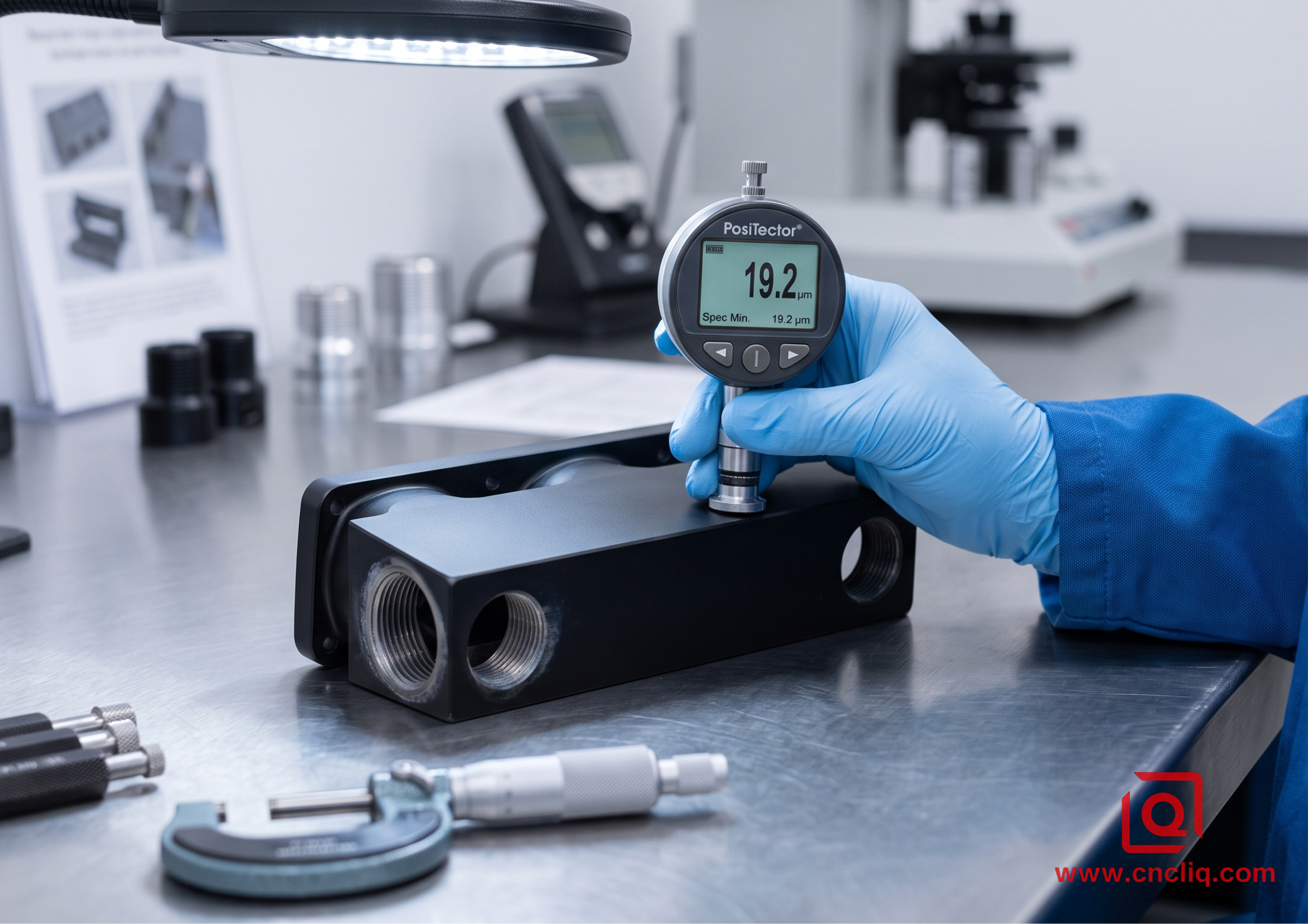
Do not ship anodized OEM parts based on visual inspection alone. Enforce a three-stage quality verification protocol in your Quality Control department:
  +-----------------------------------------------------------------------+
  |                   QUALITY CONTROL INSPECTION WORKFLOW                 |
  |                                                                       |
  |  +-------------------+    +--------------------+    +--------------+  |
  |  | Eddy-Current Gauge| -> | Nitric Acid Spot   | -> | ASTM B117    |  |
  |  | Thickness Test    |    | Seal Integrity Test|    | Salt Spray   |  |
  |  +-------------------+    +--------------------+    +--------------+  |
  |   ISO 2360 /             ASTM B136                 5% NaCl Fog @    |
  |   MIL-A-8625             2-min Spot Test           35°C (336 hrs)   |
  +-----------------------------------------------------------------------+
- Thickness Measurement (ISO 2360 / ASTM B244): Hit the surface with an eddy-current gauge calibrated on foil standards for your exact alloy grade. Log 5 spots per face; reject any batch under spec limit (like <18 μm for Type II Class 2).
- Seal Quality Check (ASTM B136): Spot 200 g/L nitric acid onto the coat for 2 minutes, rinse, then add 10 g/L Pyramine Blue stain for 5 minutes. Wipe it down with a wet rag. A dark blue stain means seal failure—usually from bath fouling or cold sealing under 92℃.
- Corrosion Testing (ASTM B117 Salt Fog): Put sample coupons into 5% NaCl fog at 35℃. Sealed Type II coatings must cross 336 hours without pits over 0.5 mm wide; Type III sealed parts must hit 1000 hours minimum.
FAQs
Q1: Will anodizing hide minor machining marks or light scratches on raw aluminum?
A: Far from it—anodizing pulls surface defects right into focus instead of masking them. Because that translucent oxide layer converts the parent aluminum directly, tool chatter, stray burrs, or heavy gouges stick out even worse post-anodize. To hit a clean, consistent texture, prep the raw metal upstream—knock down high spots with glass bead blasting or mechanical polishing to blend the substrate clean prior to tank immersion.
Q2: Why do mating components sometimes show subtle color variation despite using the same dye?
A: Color discrepancies typically stem from subtle differences in raw material mill lots or grain orientations established during milling. Variations in the alloy's internal structure alter how microscopic pore cells form and absorb dye molecules. Assembled side-by-side, parts machined from different extrusions or bar stock will reflect light differently and absorb pigment at slightly different rates.
Q3: What happens if sharp outer edges are not rounded prior to hardcoat anodizing?
A: Sharp crests force an intense concentration of electrical current during processing. This localized heat spikes bath temperatures instantly, literally baking the fresh oxide layer until it burns, chalks, or turns to dust. You end up with a fragile, toothy edge that’s structurally shot—one light knock during bench fitting or final assembly, and it chips right off.
Q4: How can precision bearing bores and internal threads be protected from the anodizing acid?
A: Operators manually install custom silicone plugs, rubber caps, or specialized masking lacquers onto precision features prior to processing. These barriers physically block the acid solution from contacting critical areas, preventing dimensional changes and keeping precision fits and pitch diameters in their raw, machined state.
Q5: Can a part with visual anodizing defects be stripped and re-processed?
A: Yes, but stripping requires dipping the component into aggressive chemical baths that dissolve the existing oxide coating. Because this process also eats away a thin layer of the underlying base metal, the part’s overall dimensions will shrink, which can easily ruin tight assembly tolerances or make precision holes loose.
Summary
Zero-defect anodizing on custom aluminum OEM parts starts at the CNC toolpath—you can’t fix bad geometry in the electro-chemical tank. Offset CAD profiles for 50/50 oxide growth, break sharp crests to at least R0.8 mm, and add relief ports to deep blind threads. Keep bath temperatures locked down and dial in current density per MIL-A-8625. This stops burning on sharp edges, color drift, and acid bleed-out cold. To wrap up, run ISO 2360 eddy-current gauge checks on each lot, verify the seal via ASTM B136, and confirm corrosion resistance using ASTM B117 salt fog exposure.
Contact Information
Disclaimer
All technical articles, material specifications, machining recommendations, and surface treatment details published on this blog are for informational and reference purposes only. Please note that general blog insights do not replace signed technical agreements. Because custom parts vary by material heat numbers, machine calibrations, and specific tolerances, binding quality specs are governed solely by your approved CAD drawings, signed contracts, and formal quality plans.
All customer case studies featured on this blog have been thoroughly anonymized and sanitized. The performance metrics, manufacturing workflows, and imagery displayed serve solely to demonstrate our custom machining capabilities and do not represent a single universal standard for all orders.
Liqin Manufacturing Team
Built on 18 years of precision engineering experience, Ningbo Liqin Industry manufactures high-tolerance metal components for demanding global markets. We operate out of a 6,500 m² production hub equipped with over 150 machines, running 4-axis and 5-axis CNC machining, mill-turn machining, cold extrusion, and pressure die casting under one roof. This setup allows us to manage projects seamlessly, taking parts from initial CAD concepts directly to finalized shipments.
We handle quality control with zero compromise. We treat tight tolerances with the engineering discipline they require. Backed by ISO 9001, ISO 13485, and IATF 16949 certifications, our QA engineers run strict IPQC, FQC, and OQC checks on every single production batch. From CMM dimensional mapping and optical profiling to hardness and salt-spray testing, we validate your critical specs upfront—so you receive drop-in ready components with zero assembly headaches or costly line stoppages. On top of manufacturing, you can rely on us for two-hour response times on new RFQs, direct support for prototype sampling, and smooth export shipping across Europe, North America, Asia, and Oceania.
Welcome your inquiries and samples. Visit our website or contact us directly for a competitive quote!
