 English




1. Introduction: The Realities of the Shop Floor
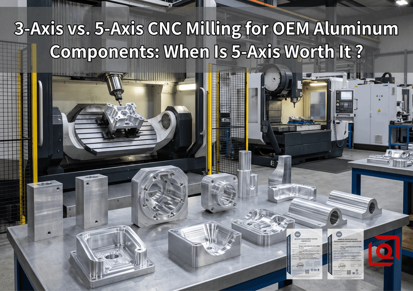
Step inside any bustling contract manufacturing facility turning out custom aluminum hardware for global original equipment manufacturers, and you will notice an interesting division of labor across the shop floor. In one bay, rows of sturdy three-axis vertical machining centers run continuously. They slice across flat mounting faces, chew out rectangular pocket geometries, and plunge tap holes down into standard extruded bars. In the adjacent cell, multi-axis machining centers hum with a very different rhythm. Their rotary platens tilt and position with zero fuss, letting rigid carbide end mills clear complex profiles, angled ports, and tight undercut ribs without chattering.
Whenever customer CAD files and prints drop into the queue, buyers and hardware engineers hit the same crossroad: Do we run this aluminum billet on our standard 3-axis mills, or does the geometry demand paying extra for a 5-axis setup?
Many general manufacturing guides try to answer this question with a neat rule of thumb: three-axis mills are for plain rectangular blocks, while five-axis machines are reserved for swooping aerospace blisks and complex artistic curves. Anyone who has ever run an active machining facility knows that this explanation leaves out the most critical details. On the shop floor, the choice between three-axis and five-axis milling is rarely about whether an external skin is curved or flat. Instead, the real decision comes down to the friction of handling:
-
How many times must an operator touch the workpiece?
-
How many individual custom fixtures must our toolmakers build, calibrate, and store?
-
How many geometric datums will we stack on top of one another as we flip the billet from face to face?
-
What does the resulting surface look like when tools blend cut paths across different operations?
If you are an OEM engineer buying machined aluminum parts, understanding this practical dynamic is the quickest way to protect your piece-part budgets without compromising structural tolerances. Let us bypass the academic theory and explore how these two milling workflows actually behave inside a working machine shop.
2. Machine Kinematics: Understanding the Motion
To see where the costs and capabilities diverge, you first need to picture how cutting tools interact with raw aluminum stock under both machine setups.
Any CNC mill operates around 3 basic linear axes. The spindle or table travels side-to-side along the X-axis, front-to-back along the Y-axis, and drops straight up and down on the Z-axis. On a standard 3-axis vertical machine, the aluminum blank sits bolted directly to the bed, usually clamped tight in a vise or pinned to a grid plate. The cutter only ever attacks stock from the top. If your print calls for a threaded hole on face 1, a counterbore on the left flank, an angled bore on the opposite wall, and a clearance pocket underneath, the spindle cannot hit those profiles in 1 shot. An operator has to stop the run, loosen the jaws, blow off the chips, flip the block by hand, pick up the work offset, and hit green again.
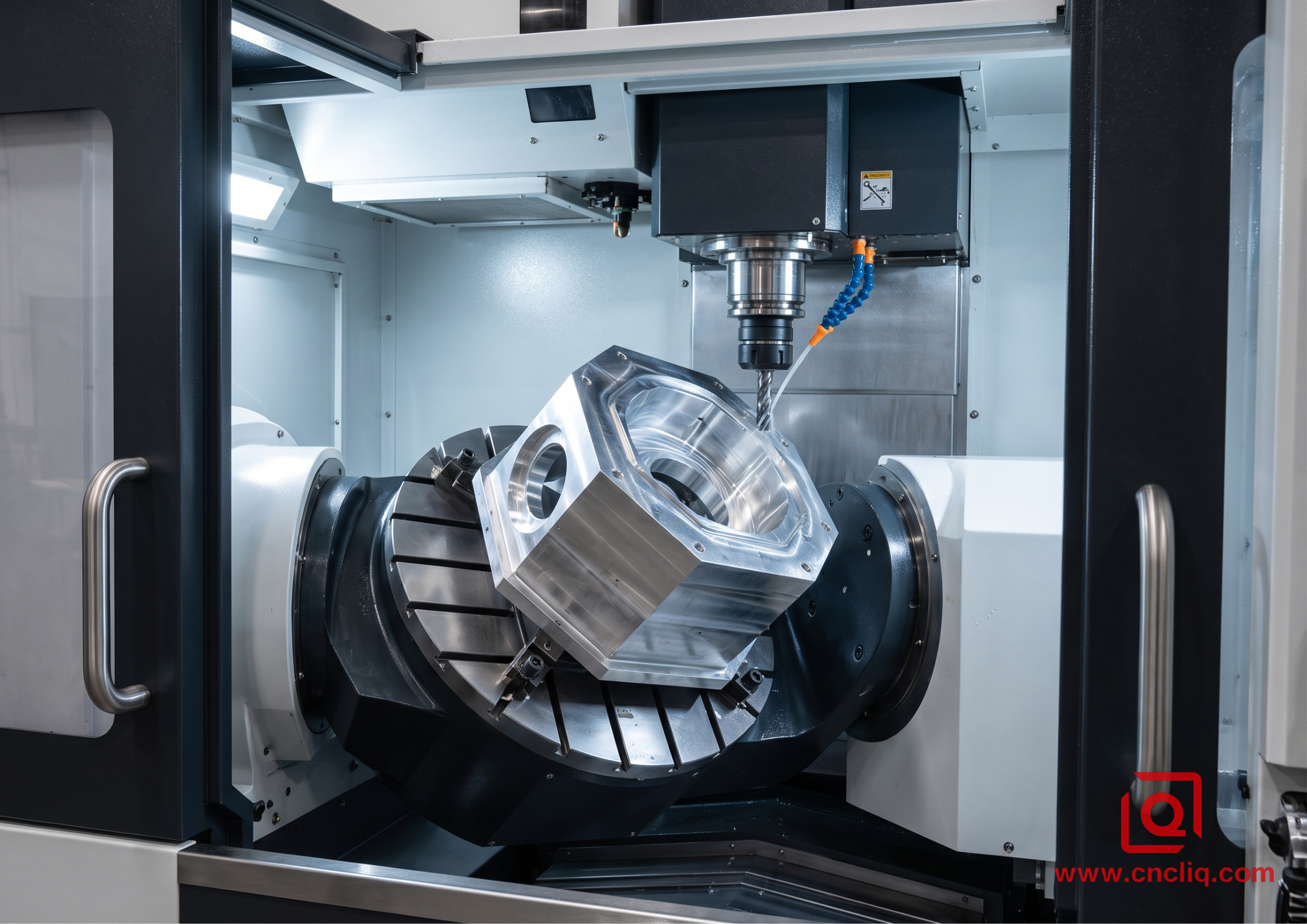
5-axis setups throw 2 rotational axes into the mix. On a classic trunnion rig, the platter tips along the X-axis (giving you an A-axis) and swings continuously around the Z-axis (your C-axis). Swivel-head units handle it differently—the spindle head does the tilting while the table spins below. Either way, the cutting tool gains direct access to five different sides of a solid prism in one continuous sequence.
Inside contract machining facilities, machinists generally divide five-axis work into two distinct operational modes:
Continuous Five-Axis Machining
In this mode, all five axes move at the exact same instant while the cutter engages the material. The spindle twists and sweeps across the workpiece as the table pitches and rolls. This continuous coordination is mandatory when you are cutting dynamic turbine impellers, complex aero-surfaces, or organic shapes found in advanced medical prosthetics. However, continuous five-axis contouring requires intricate computer-aided manufacturing toolpaths, intensive computer simulation to rule out spindle collisions, and specialized tool geometries.
Positional "3+2" Milling
This is where the vast majority of industrial aluminum components find their real sweet spot. In a 3+2 setup, the machine uses its two rotary axes simply to tilt and orient the raw aluminum block to an exact spatial angle. Once the workpiece is locked in position, the rotary brakes engage with hydraulic clamping force. The machine then cuts the feature using standard, rigid, linear three-axis movements.
Instead of moving all axes simultaneously, 3+2 milling functions as an automated indexing system. It allows a shop to cut multiple faces, mill angled clearance lands, and drill compound port passages across an aluminum housing in a single clamping cycle. Understanding this distinction is vital for OEM buyers: you do not need sweeping aircraft wing curves to profit from five-axis machining; you simply need a part with features distributed across multiple planes.
3. The Three-Axis Advantage: Where Simplicity Wins
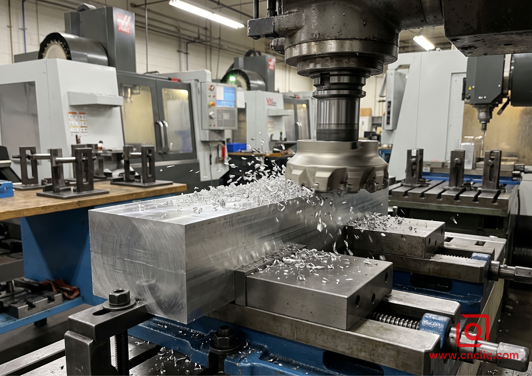
Because multi-axis equipment looks impressive and carries high-tech appeal, engineers sometimes assume that routing every precision part through a five-axis machine is a natural upgrade. That assumption is an easy way to inflate your procurement costs. The conventional three-axis machining center remains the most dependable, cost-effective tool in the manufacturing world for a massive family of parts.
First and foremost, three-axis mills enjoy an undeniable machine-rate advantage. A dependable production-grade three-axis vertical mill carries an internal billing rate roughly half that of a high-end five-axis trunnion center. Upfront CapEx on a 3-axis spindle runs way lower, wear spares are cheap, routine PM is painless, and regular setup guys can dial in parts without spending years mastering multi-axis kinematics.
Take an everyday aluminum cold plate, a flat front-panel enclosure, or an ordinary mounting lug. Raw stock begins as an extruded slab or a square saw-cut billet of 6061-T6. All the crucial features—such as face-milled reference lands, internal O-ring seal grooves, weight-reduction cavities, and through-hole patterns—reside cleanly on the top surface. The only operation required on the reverse side is skimming off the excess stock thickness and chamfering the perimeter edges.
Routing this kind of component through a five-axis mill provides virtually zero technical benefit. A three-axis mill can clamp the plate flat against a sacrificial bed or hold it inside standard vise jaws. It can push an aggressive face mill across the aluminum surface at very high spindle speeds, rip out the pocket cavities, drill the hole groups, and finish the face in record time. The operator makes a single flip to clean up the backside, and the part is done.
Furthermore, three-axis mills often provide superior raw rigidity when you are hogging massive amounts of metal out of heavy aluminum plates. Because the workpiece mounts directly to the heavy cast-iron table rather than riding suspended between rotary trunnion bearings, the machine can absorb massive cutting forces without setting off chatter or resonance. If your design lives primarily on one or two flat planes, keeping the job on a three-axis machine is the most responsible, budget-friendly engineering choice you can make.
4. The Five-Axis Breakthrough: Eliminating Setups and Stack-Up
Where does the three-axis workflow begin to stumble? The bottleneck rarely shows up in the cutting speed of the machine spindle. Instead, the trouble starts with human touch points, handling time, and the physics of datum transfer.
Every time a machinist loosens a vise to reposition an aluminum part, several unavoidable variables creep into the production process:
-
The operator must clean every chip off the locating surfaces, because a stray flake of aluminum trapped beneath a datum pad can tilt the workpiece by several hundredths of a millimeter.
-
The vise jaws must clamp down with consistent torque to prevent part distortion.
-
The machine operator or an automated touch probe must sweep the newly exposed surfaces to establish a new coordinate work offset.
In our trade, this is known as datum stacking. When you cut the primary bore in Setup 1, flip the part onto its side for Setup 2 to drill a mounting hole, and flip it again for Setup 3 to mill an angled boss, the geometric relationship between those features depends on the mechanical accuracy of three separate physical setups. If your engineering drawing contains strict Geometric Dimensioning and Tolerancing requirements—such as calling out tight true position between holes on opposite sides or demanding strict perpendicularity across distant faces—holding those specs across multiple manual setups becomes a nerve-racking task. Scrap rates rise, inspection cycles on the coordinate measuring machine take longer, and overall production momentum slows down.
This is precisely where five-axis machining delivers its greatest financial and quality return. When you clamp an aluminum billet into a five-axis machine—often holding it by a minimal clamping strip along the bottom stock edge—the machine gains unfettered access to the top and all four lateral sides.
Because the workpiece stays locked in place, the machine references every cut, bore, and face back to one master coordinate system. The angular accuracy between Face 1 and Face 4 no longer relies on how carefully an operator seated the part against a stop pin; it depends purely on the precision optical encoders built into the machine’s rotary axes.
Beyond datum stability, five-axis machining solves an everyday tooling dilemma: cutter stickout and vibration. Picture an aluminum enclosure with a deep interior pocket measuring 100 millimeters down from the rim. To reach the bottom floor on a standard three-axis vertical mill, you must mount an end mill with a very long reach.
Long, slender cutting tools act like cantilevered diving boards. Once the revving cutter bites aluminum, chip loads push the shank out of true. To stop the carbide from whistling, vibrating, or outright snapping in two, the CAM guy has to choke the feed, pull back depth of cut, and baby the path. Even with light passes, the pocket ribs still show witness marks, leaving bench hands to scrape off chatter ripples or scrub the cosmetics clean.
Now visualize that exact same deep pocket on a five-axis center. Instead of plunging a spindly, long-reach cutter straight down, the trunnion table tilts the entire workpiece over at an angle. This dynamic tilt lets the spindle reach right into the lower corner of the pocket using a short, rigid tool clamped securely in a heavy-duty toolholder.
Because short tools do not suffer from severe bending forces, the machine can run at elevated feed rates and push high chip volumes without chatter. The mill sweeps flat, mirror-straight sidewalls with rock-solid Ra values, while edge life jumps significantly because the flutes dodge destructive harmonic pounding. Stepping down from a noodly, chatter-prone reach to a stubby carbide end mill flips a production logjam into a run-and-forget setup.
5. Comprehensive Comparison: 3-Axis vs. 5-Axis Milling
To help you weigh your options during supplier audits or internal design reviews, the table below lines up the practical operational differences and business impacts between these two machining strategies for OEM aluminum parts:
| Operational Parameter | Standard 3-Axis CNC Milling | Positional (3+2) & Continuous 5-Axis | Real-World Impact on OEM Production |
| Hourly Machine Burden Rate | Lower baseline shop cost ($45 to $75 per hour) | Higher capital investment ($95 to $160 per hour) | 5-axis must offset higher hourly rates by cutting handling steps or shortening cycle times. |
| Typical Setup Iterations | 2 to 6 individual setups and flips | 1 to 2 setups total (complete in one cycle) | 5-axis eliminates human touch points and slashes cumulative setup labor. |
| True Position & Alignment | Moderate consistency (dependent on setup datums) | Superior accuracy (referenced to single coordinate system) | 5-axis easily holds tight GD&T callouts across complex intersecting planes. |
| Tool Length-to-Diameter Ratios | Requires long-reach tools for deep cavities | Permits short, rigid, low-deflection tools | Short cutters reduce chatter, improve wall finishes, and allow higher feed rates. |
| Dedicated Tooling & Fixtures | High fixture spend (multiple soft jaws and angle plates) | Minimal fixture needs (standard dovetail or self-centering vise) | 5-axis saves substantial non-recurring engineering costs on new product introductions. |
| CAM Programming Complexity | Straightforward, short toolpath generation time | Demands collision checking and machine-model simulation | Multi-axis programming takes longer up front to guarantee spindle clearance. |
| Surface Finish & Blending | Tool-step mismatch marks common across setups | Smooth blended cuts and uniform surface textures | 5-axis minimizes post-machining bench grinding, sanding, and secondary rework. |
| Ideal Component Profiles | Flat plates, structural brackets, single-face manifolds | Multi-sided housings, angled port manifolds, thin-wall shells | The distribution of features determines cost savings far more than outer dimensions. |
6. Real-World Case Study: Machining an OEM Aerospace Sensor Housing
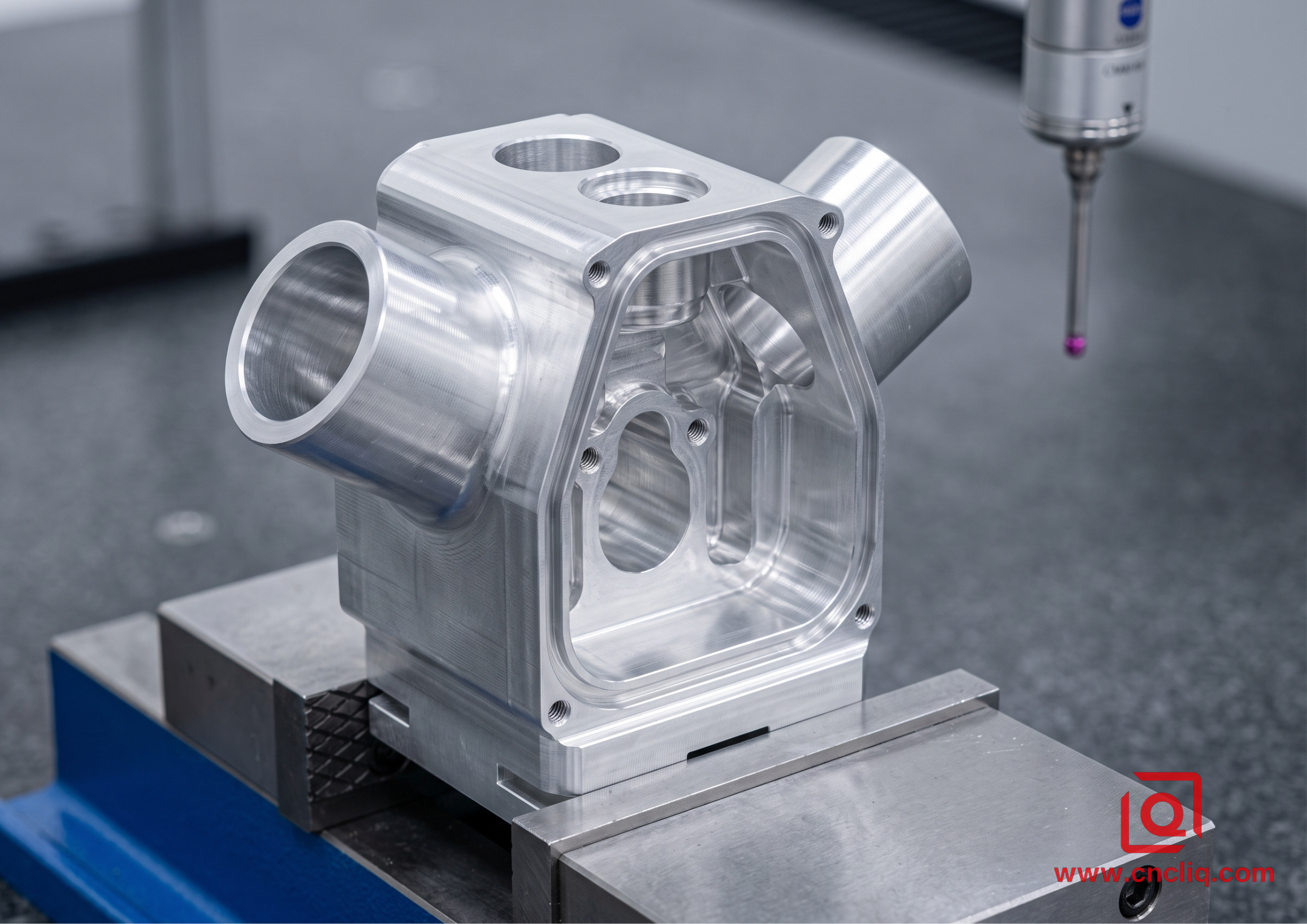
To see how these mechanical dynamics translate into direct dollars and cents, let us walk through an actual production case study from our shop floor.
A commercial drone outfit came to our team to build an avionics optical pod shell. We cut the unit out of solid 6061-T6 aero-grade aluminum billet, holding a raw envelope of 145 millimeters by 120 millimeters by 85 millimeters. Target call-outs sat at a firm run rate of 350 finished parts a month.
The engineering drawing carried several demanding geometric features:
-
The internal core was hollowed out to minimize flight payload weight, leaving thin perimeter walls.
-
Four side apertures emerged from the main body at an unusual compound angle of 27 degrees.
-
The true position of each angled aperture had to stay within 0.015 millimeters relative to the main optical bore.
-
The internal sealing track called for an uninterrupted, smooth surface finish of Ra 0.8 to ensure weather-tight environmental sealing.
The Initial Three-Axis Routing Plan
The customer’s original manufacturing plan relied on conventional three-axis machining steps:
-
Operation 10: Face the top datum surface, rough out the primary center cavity, and drill two internal locating dowel holes (12 minutes).
-
Operation 20: Flip the block into a second vise, square the bottom mounting face, and carve the external perimeter profile (10 minutes).
-
Operations 30 through 60: Mount the semi-machined part onto four separate angled sine-plate fixtures. The operator had to mount the part, indicate the setup to confirm alignment, drill the angled port, bore the inner diameter, mill the mounting boss, and unclamp the unit. This cycle repeated across all four angled faces (8 minutes per side, totaling 32 minutes).
Under this conventional workflow, total machining time reached 54 minutes per piece across six separate machine setups. Non-recurring tooling costs totaled $4,200 to fabricate the precision angled sine plates and custom soft jaws.
Worst of all was the scrap rate. Even with skilled machinists running the line, the tiny variations introduced across four separate manual re-clamping operations caused the true position of the angled bores to drift. The production line struggled with an 8.5% scrap rate during initial pilot runs, tying up our CMM inspection station with tedious troubleshooting.
The Five-Axis Engineering Overhaul
Our engineering team sat down with the customer’s sourcing group and proposed migrating the entire job to a five-axis trunnion machining center using 3+2 positional toolpaths:
-
Preparation: The saw-cut aluminum billets spent 1.5 minutes on a manual prep mill, where a shallow dovetail profile was cut into the bottom waste stock.
-
Operation 10 (The Main Cycle): The operator clamped the billet into a five-axis self-centering vise via the dovetail grip. From this single setup, the machine ran continuously. The trunnion table tilted the workpiece smoothly to machine the top cavity, swept the side walls, indexed to 27 degrees to bore all four angled sensor ports, and traced the internal sealing groove using a rigid ball-nose cutter (19 minutes total).
-
Operation 20 (Dovetail Removal): The operator transferred the part to a simple utility mill, clamping the finished body inside smooth soft jaws to skim off the dovetail carrier foot on the bottom face (3.5 minutes).
The Financial Outcome
The revised five-axis workflow cut total machining cycle time from 54 minutes down to 24 minutes. Tooling expenses dropped from $4,200 for specialized sine fixtures down to $650 for a standard five-axis dovetail vise jaw set. Scrap rates plummeted from 8.5% to under 0.5%, because every critical aperture was bored in reference to the original work coordinate system without manual repositioning.
Even though our five-axis machining center billed at an hourly rate more than double that of the three-axis mill, the finished cost per housing dropped by 28%. The combined savings from shorter spindle times, zero fixture overhead, and near-zero scrap easily outweighed the higher machine-hour rate.
7. FAQs
1. Does choosing five-axis machining automatically make my purchase order more expensive?
Not necessarily. While a five-axis machine carries a higher hourly rate than a three-axis mill, the final unit price depends on total cycle time, scrap risks, and fixture tooling expenses. If an aluminum part requires three or more separate operations on a three-axis mill, a five-axis setup is often cheaper overall. It eliminates manual handling steps, does away with custom soft-jaw fabrication, and avoids the scrap common to multiple manual clampings.
2. What types of parts should definitely remain on standard three-axis mills?
Flat baseplates, wide mounting brackets, structural heat sinks, and any component where all the milled pockets, holes, and edge profiles sit on one or two opposing faces. If a machine operator can finish your part by simply cutting the top side and flipping it over once, moving that part to a five-axis machine adds programming overhead without delivering any real engineering benefit.
3. How does five-axis machining improve overall part accuracy?
On a three-axis machine, cutting multiple sides of an aluminum block requires unfastening and re-clamping the part in different orientations, which inevitably introduces minor mechanical alignment errors across setups. On a five-axis machine, the spindle reaches five sides of the part in a single clamping cycle. Because every feature shares the exact same coordinate datum, the machine can hold tight true-position, concentricity, and perpendicularity tolerances down to 0.015 millimeters without relying on operator touch.
4. Does five-axis milling speed up delivery times for early prototype runs?
Yes, often by a wide margin. Although five-axis computer programming and virtual crash simulations take more preparation up front, the shop saves substantial time on the floor. The manufacturing team does not need to design, machine, and calibrate multiple custom workholding fixtures or specialized soft jaws. For complex, multi-sided aluminum prototypes, this can shave days or weeks off your initial delivery schedule.
5. What design adjustments can engineers make to lower five-axis machining costs?
Design engineers should aim to use standardized internal corner radii so the shop can clear pockets with off-the-shelf tools rather than custom cutters. It also helps to designate a dedicated clamping area—such as a bottom lip or dovetail tab—so the machine can access five sides without interference. Finally, avoid deep, narrow channels whenever possible; keeping cavity proportions reasonable allows the shop to use short, rigid tools at maximum feed rates.
8. Summary: Sourcing Checklist for Engineering Teams
Selecting between three-axis and five-axis CNC milling is an economic decision driven by part geometry, not an upgrade to buy for its own sake. When you review your next batch of custom aluminum drawings, use this straightforward checklist to guide your manufacturing conversations:
-
Evaluate the Working Faces: Look closely at where your features sit. If your aluminum part requires milling, tapping, or boring on four or more sides, a five-axis setup will almost certainly cut your overall costs by removing repetitive handling steps.
-
Examine Your GD&T Scheme: When you see strict perpendicularity callouts, true-position flags under 0.02 millimeters, or tight concentricity requirements connecting features on different faces, multi-axis machining is the safest path to avoid tolerance stack-up and scrap.
-
Look Beyond Hourly Machine Rates: Never judge an initial supplier quotation purely on hourly spindle fees. Be sure to calculate the hidden costs of multi-stage tooling fixtures, manual setup labor, and higher scrap allowances when comparing three-axis and five-axis alternatives.
-
Open the Conversation Early: Involve your manufacturing partner during the early design phase. Simple tweaks to your pocket corner radii, wall thicknesses, and workholding lands can help the shop harness the speed of five-axis machining while keeping your piece-part budgets firmly on target.
Contact Information
Disclaimer
All technical articles, material specifications, machining recommendations, and surface treatment details published on this blog are for informational and reference purposes only. Please note that general blog insights do not replace signed technical agreements. Because custom parts vary by material heat numbers, machine calibrations, and specific tolerances, binding quality specs are governed solely by your approved CAD drawings, signed contracts, and formal quality plans.
All customer case studies featured on this blog have been thoroughly anonymized and sanitized. The performance metrics, manufacturing workflows, and imagery displayed serve solely to demonstrate our custom machining capabilities and do not represent a single universal standard for all orders.
Liqin Manufacturing Team
Built on 18 years of precision engineering experience, Ningbo Liqin Industry manufactures high-tolerance metal components for demanding global markets. We operate out of a 6,500 m² production hub equipped with over 150 machines, running 4-axis and 5-axis CNC machining, mill-turn machining, cold extrusion, and pressure die casting under one roof. This setup allows us to manage projects seamlessly, taking parts from initial CAD concepts directly to finalized shipments.
We handle quality control with zero compromise. We treat tight tolerances with the engineering discipline they require. Backed by ISO 9001, ISO 13485, and IATF 16949 certifications, our QA engineers run strict IPQC, FQC, and OQC checks on every single production batch. From CMM dimensional mapping and optical profiling to hardness and salt-spray testing, we validate your critical specs upfront—so you receive drop-in ready components with zero assembly headaches or costly line stoppages. On top of manufacturing, you can rely on us for two-hour response times on new RFQs, direct support for prototype sampling, and smooth export shipping across Europe, North America, Asia, and Oceania.
Welcome your inquiries and samples. Visit our website or contact us directly for a competitive quote!
