 English




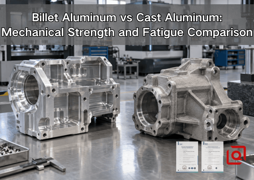
Are you weighing billet aluminum against cast aluminum for a bracket, housing, manifold, or rotating part that will be loaded again and again? The question turns up often at our quotation desk, usually with one assumption already attached: billet must be stronger. That answer is too easy. In the workshop, we look at the named alloy and temper first. Then we ask where the load travels, how the blank was made, what the surface will look like after machining, and where a crack could get started. A sound A356-T6 casting may suit a production housing very well. A 7075 part can still fail early when its grain direction, radius, or tool finish is wrong.
We will separate a one-time overload from millions of smaller cycles, look at pores and cutter marks, and finish with the information an RFQ should contain. The useful route is the one whose weak points you can verify.
Short answer: If the part is highly loaded and quantities are still low, wrought stock is often the easier starting point. Its properties are usually steadier and internal discontinuities are less troublesome. Casting earns its place when the shape is difficult to cut, material loss is high, or volume can justify tooling. On a cyclic or safety-related job, the purchasing label proves very little; certificates, process records, critical-zone inspection, and part testing do.
1. What “Billet” and “Cast” Actually Mean
First, a terminology trap. Wrought stock is not metal that somehow escaped casting. The mill begins with cast metal, then works it by rolling, extrusion, drawing, or forging. When a buyer asks us for a “billet part,” the usual meaning is a finished component cut from bar, plate, or extrusion. On real RFQs, that stock is commonly 6061-T6/T651, 6082-T6, 2024-T351, or 7075-T6/T651.
A finished casting takes a shorter metallurgical route: the alloy freezes in a mold that already resembles the part. Even so, the word “cast” is not a complete specification. Sand molds, gravity dies, low-pressure systems, and high-pressure dies fill and cool differently. They leave different wall limits and different defect patterns. Treating gravity-cast A356-T6 and die-cast A380 as one material is like treating every steel as the same grade.
This distinction matters because shape and metallurgy arrive together. Billet machining lets the programmer revise pockets, holes, and datums without buying a new mold. Casting creates curved ribs, enclosed passages, bosses, and thin walls efficiently, but tooling, gating, venting, local section thickness, and heat treatment influence the result. Liqin’s guide to aluminum machining processes explains how milling, turning, and extrusion shape a production plan, while the die casting versus CNC machining guide focuses on volume and cost. This article stays deliberately narrower: strength and fatigue.
2. Mechanical Strength: Compare Alloy to Alloy, Not Label to Label
Static strength describes what happens when load rises once. Yield strength marks the point where permanent deformation begins. Ultimate tensile strength is the maximum engineering stress reached in a tensile test. Elongation indicates how far a specimen stretches before fracture and gives a useful, though incomplete, view of ductility. Designers also care about fracture toughness, bearing strength, shear strength, temperature, and corrosion environment.
The values below are representative reference values, not design allowables. Product form, thickness, orientation, heat treatment, specimen source, and test standard all matter. Properties measured from separately cast bars may not match coupons cut from a thick or poorly fed production casting. The North American Die Casting Association identifies typical die-cast alloy values as reference information rather than guaranteed design minima in its Product Specification Standards.
|
Material / route |
Typical yield strength |
Typical ultimate tensile strength |
Typical elongation |
Practical interpretation |
|
6061-T6 wrought bar or plate |
About 276 MPa |
About 310 MPa |
About 8%–12%, depending on form and thickness |
Balanced strength, corrosion resistance, machinability, and availability; a common baseline for billet-machined parts. |
|
7075-T6 wrought product |
About 500 MPa |
About 570 MPa |
About 7%–11%, depending on direction and thickness |
Much higher static strength, but greater sensitivity to corrosion environment and short-transverse orientation; specifications must name product form and temper. |
|
A356-T6 permanent-mold casting |
Often about 170–210 MPa |
Often about 230–290 MPa |
Often about 3%–8% |
Useful for structural castings when melt quality, solidification, heat treatment, and defect controls are qualified. |
|
A380 high-pressure die casting |
About 159 MPa in NADCA typical data |
About 324 MPa in NADCA typical data |
About 3.5% in separately die-cast specimens |
Excellent castability and high-volume economics; real-part properties vary with wall thickness, porosity, skin, and process conditions. |
Notice why a single “percentage stronger” claim is misleading. A380 can show a respectable ultimate tensile value but a much lower yield value and lower ductility than 6061-T6. Meanwhile, 7075-T6 exceeds both in static strength but may be unnecessary, harder to protect in certain corrosive service, and less forgiving across unfavorable grain directions. The engineer’s job is to compare the property that controls the failure mode.
Why wrought stock is usually more consistent
Put a sawn plate edge beside a cut casting and the difference is often visible before the microscope comes out. Rolling or extrusion has pressed and stretched the solidified structure. Grains become directional; particles are broken up or redistributed; some original voids are closed. The mill product is generally dense and predictable from lot to lot. That makes it a practical choice for a prototype bracket, a low-volume manifold, or any job where one hidden pore would upset a sealing face.
There is a catch, and it is easy to miss on a material certificate. Wrought stock has direction. The mill calls those stock directions longitudinal, long-transverse, and short-transverse. A crack does not grow at the same rate in all 3. When the assembly pulls across the least favorable direction, a stronger alloy number on the purchase order may leave the basic layout problem untouched.
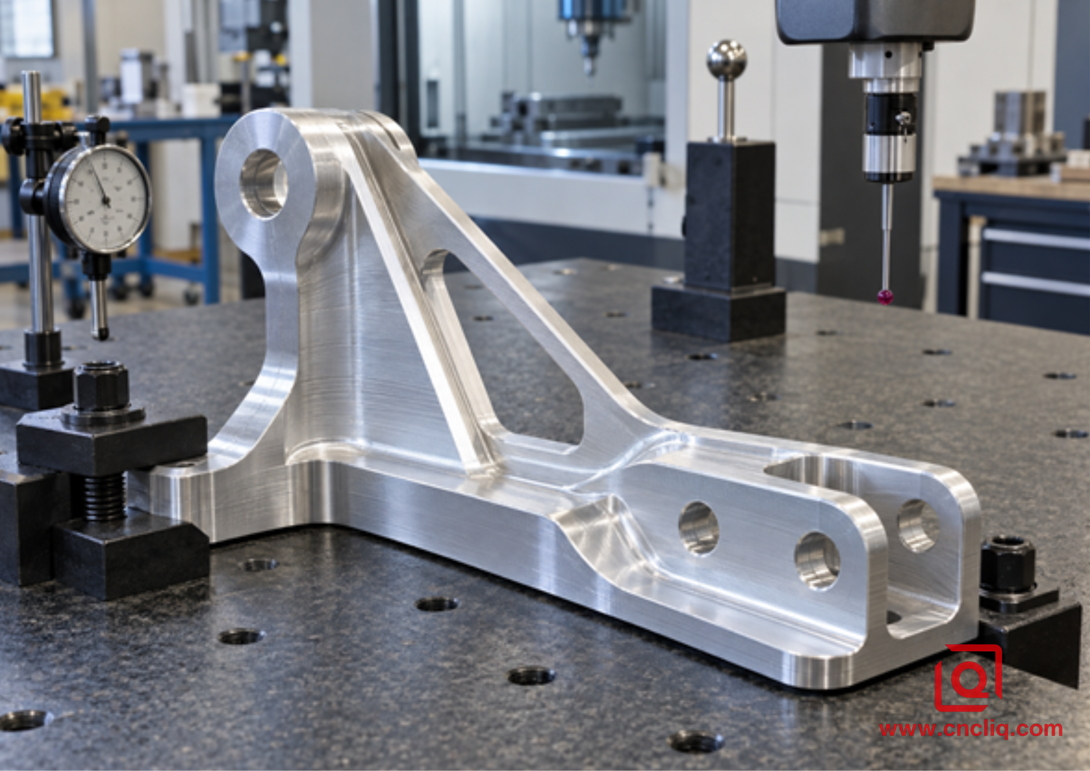
This bracket started with clean stock, but the drawing and the cut still matter: the inside radius, stock direction, last finishing pass, and clamp load all leave a trace in its fatigue performance.
Why casting performance has a wider spread
A casting tells a different story when it is cut open. Gas may leave rounded pores. An underfed heavy boss can shrink internally. Folded oxide films, inclusions, cold shuts, or a locally coarse structure may also be present. None of those words automatically rejects a part. Location rules the decision. A small pore buried in a quiet, thick wall is one problem; the same pore opened by a cutter at the root of a loaded rib is another.
Cooling rate also changes properties. A thin die-cast wall near the tool surface may cool quickly and form a relatively dense skin, while a thick boss cools more slowly. If machining removes the skin or intersects a pore cluster, the local fatigue result can change. A casting drawing should therefore define critical zones instead of applying expensive inspection to every square millimeter.
3. Fatigue: What a Static Test Does Not Show
A part may look fine after one proof load and crack months later. That slow accumulation of damage under repeated stress is fatigue. A component can crack even when every cycle stays below its static yield strength. Aluminum alloys generally do not show the clear endurance plateau associated with some steels, so fatigue strength must be stated at a chosen number of cycles and under a defined stress ratio. A value without test conditions is incomplete.
ASTM E466 covers force-controlled constant-amplitude axial fatigue testing of metallic specimens in air at room temperature. It also makes an important boundary clear: the procedure is for specimens, not complete products. The ASTM E466 description is useful when specifying how comparative S–N data were generated. Real parts still need suitable safety factors, load spectra, environmental allowances, and validation.
Read an S–N chart carefully: the vertical axis is stress amplitude and the horizontal axis is life. For 6061-T6, several rotating-beam references sit in the mid-90 MPa range near 100,000,000 cycles, under their stated laboratory conditions. The spread for A356-T6 is broad because the casting route and defect population matter. One permanent-mold dataset reports 81–99 MPa at 10,000,000 cycles for its model at R = −1; sand-cast references can sit lower. The ranges can overlap, so an alloy name by itself is not evidence that a finished component will reach its target life.
|
Fatigue variable |
Why it changes the result |
What to put on the drawing or RFQ |
|
Stress ratio, R |
Fully reversed tension-compression is more damaging than a small fluctuation around a positive mean stress. |
Minimum and maximum load, preload, pressure, or torque; do not provide only “cycles.” |
|
Cycle target |
Stress acceptable for 100,000 cycles may not survive 10,000,000 cycles. |
Required life, duty cycle, starts/stops, overloads, and inspection interval. |
|
Surface condition |
A scratch that looks cosmetic can become the first notch. Coarse cutter lines, flash, and corrosion pits do the same. |
Finish only where needed; define protected radii and edges. |
|
Geometry and notch factor |
Small fillets, thread runouts, keyways, and abrupt wall changes concentrate stress. |
Critical radii, thread relief, datum scheme, and load direction. |
|
Defects |
Pores or oxide films near the surface can behave like pre-existing cracks. |
Critical-zone radiography, CT, dye penetrant, pressure test, or sectioning plan. |
|
Environment |
Corrosion, temperature, and fretting can shorten fatigue life. |
Fluid, temperature range, salt exposure, coating, mating material, and maintenance conditions. |
Cracks usually start at a detail, not in an average property table
When a failed component comes back to the bench, the crack origin is rarely mysterious for long. We commonly find it at an inside corner that was made sharp for tool access, the last thread beside a shoulder, a chatter stripe in a fillet, or a hurried deburring mark. On cast work, facing can uncover a pore at exactly the wrong spot. The average stress reported by a model may be comfortable while the small patch at that detail is doing far more work.
For billet parts, use generous machinable radii and orient stock so the critical stress path does not rely on the weakest material direction. Control cutter engagement and tool condition in critical fillets. Avoid cosmetic hand blending unless the method, direction, and acceptance limit are defined. For cast parts, move gates, overflows, ejector features, and heavy-to-thin transitions away from fatigue hot spots. Machine datums and sealing faces with enough support to avoid exposing or enlarging defects.
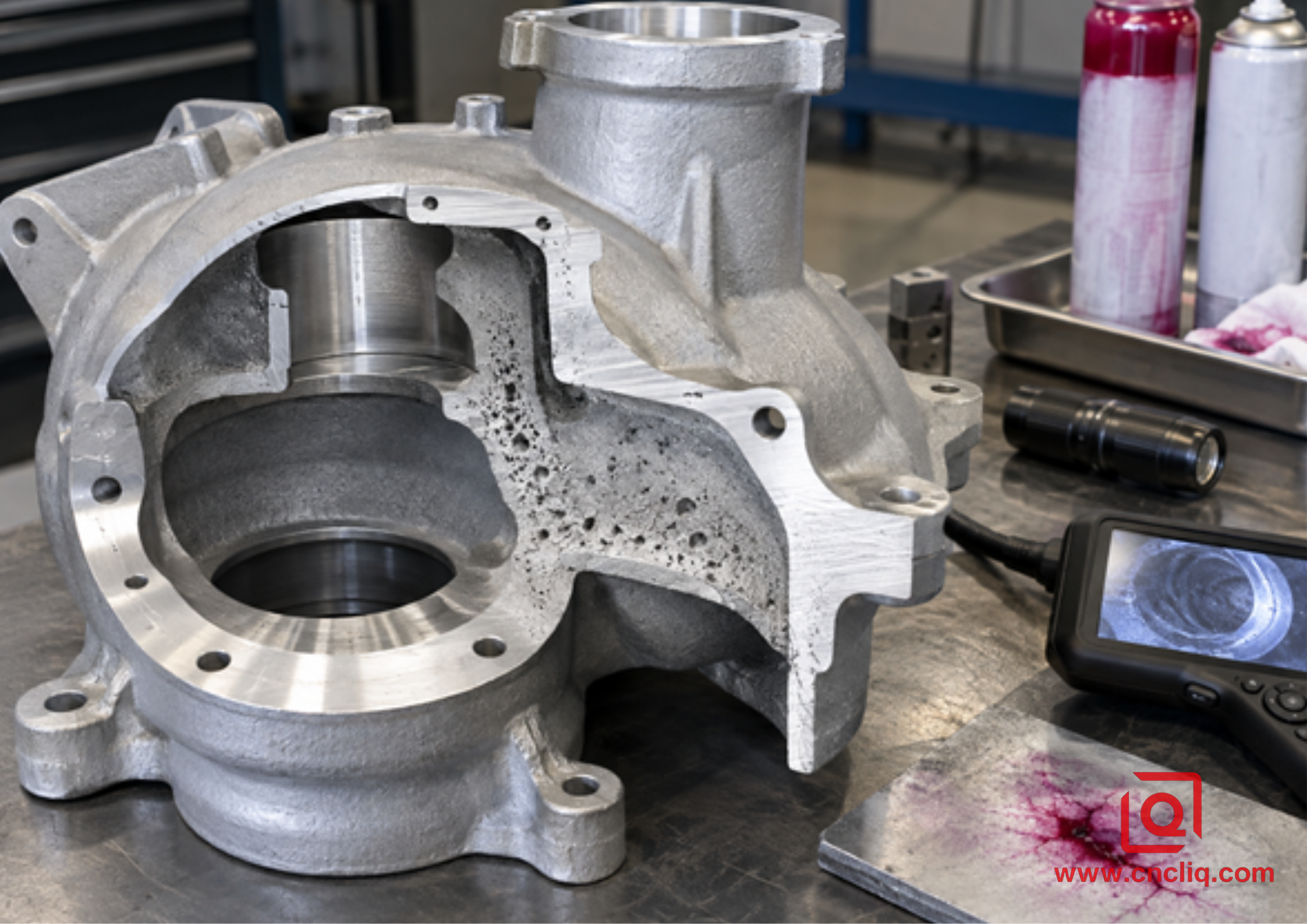
A pore in a quiet wall and a pore at a loaded thread are not equivalent. Inspect where stress, sealing, or a thin ligament makes the defect consequential.
4. Billet vs Cast Aluminum: A Practical Decision Matrix
|
Project condition |
Usually favors billet machining |
Usually favors casting plus finish machining |
|
Prototype or frequent design changes |
A revision normally stays in CAD, CAM, and the fixture plan. |
Even soft tooling has to be altered or replaced when the shape moves. |
|
High cyclic load with uncertain load path |
Predictable wrought stock and simpler defect control reduce development risk. |
Possible after process qualification, critical-zone inspection, and component testing. |
|
Complex hollow shape or internal passage |
Limited by cutter access, drilling intersections, plugs, or multi-piece assembly. |
Cores and near-net forming can create geometry machining cannot reach economically. |
|
High annual volume |
Cycle time and chip waste can dominate piece price. |
Tooling can be amortized; machining is limited to interfaces, bores, threads, and seals. |
|
Very tight datum relationships |
One-setup multi-axis machining can hold related features directly. |
Cast variation must be located and supported; finish machining restores precision. |
|
Cosmetic anodizing |
Wrought 6061 often gives a more uniform appearance with controlled chemistry and preparation. |
High-silicon cast alloys can show color variation; appearance samples and limits matter. |
|
Pressure or vacuum boundary |
Dense stock reduces porosity-related leak risk; drilled intersections still need validation. |
Near-net passages are attractive, but porosity, impregnation rules, and pressure testing must be planned. |
For a custom hydraulic manifold, billet often makes sense during development because port positions change and leakage risk must be low. Liqin’s precision aluminum manifold machining solution is a relevant product example: multi-face channels, sealing features, and bores are machined around a controlled datum plan. For a thin-ribbed electronics enclosure at thousands of units per year, a casting with localized CNC finishing may be more economical and mechanically adequate.
5. A Shop-Floor Case: Converting a Repeatedly Loaded Actuator Bracket
An anonymized industrial automation customer approached Liqin with a compact actuator bracket used in a pick-and-place module. The original concept was a thin-wall aluminum casting with 2 bearing bores, 4 mounting pads, and a rib joining the pivot boss to the base. The bracket saw reversing acceleration throughout every machine cycle. Early prototypes were needed before annual volume was stable.
The first review did not begin with “cast or billet?” It began with the load path. The highest alternating stress ran through the inside radius where the vertical rib met the pivot boss. That region also sat close to a thick-to-thin transition in the casting concept, making shrinkage control and inspection important. Because the customer was still changing the pivot position, hard tooling would have frozen the geometry too early.
For validation, the team chose 6061-T651 plate and used 2 setups. Roughing left stock around the bores and rib; the bracket was then released and re-clamped in soft jaws before finishing. A larger, cutter-friendly radius and a continuous finishing path removed the dwell mark at the hot spot. CMM inspection covered bore position, perpendicularity, and free-state flatness.
Once testing fixed the geometry and volume rose, the review added a permanent-mold A356-T6 blank with the 2 bores and pads finish-machined. The proposal specified local radii, feeding at the pivot boss, machining allowance, first-article radiography at the junction, and component fatigue validation. The customer could now compare landed cost with qualification risk.
This case illustrates the useful answer: billet can reduce development risk, while a qualified casting can reduce recurring material and spindle time. A staged plan lets testing—not slogans—decide when to switch.
6. The Hybrid Route: Cast the Shape, Machine the Function
Many production parts should not be forced into a pure billet-versus-cast choice. A hybrid route uses casting for broad geometry and CNC machining for features controlling assembly. In practice, we leave ribs, bosses, the outside envelope, and unreachable passages to the mold. The spindle then concentrates on what the assembly feels: bearing seats, dowel holes, O-ring grooves, ports, gasket faces, and datum pads.
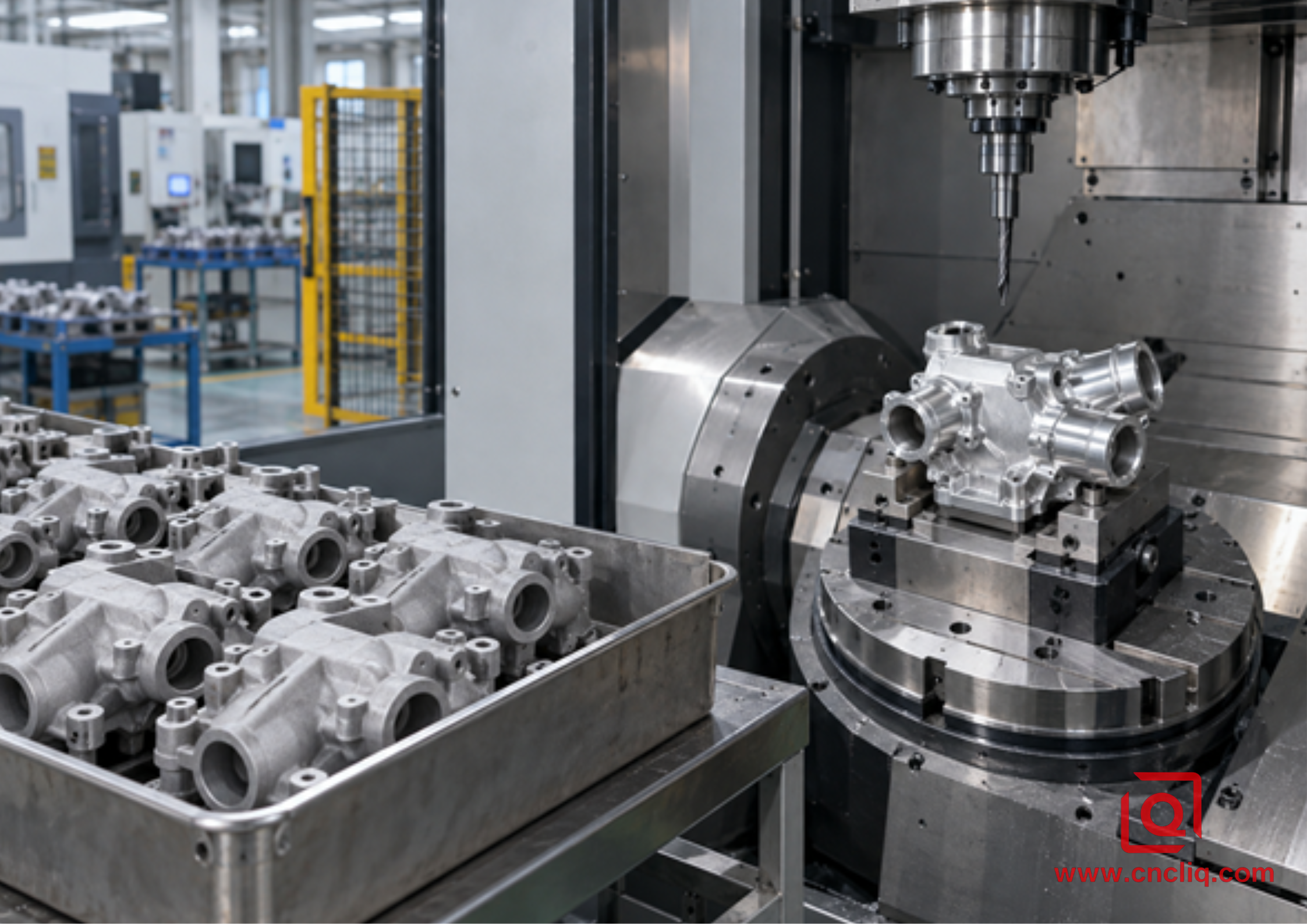
A hybrid route reserves CNC time for critical interfaces while casting creates the near-net structure.
Datum strategy is crucial. Do not locate a thin casting from a cosmetic, variable surface and expect a machined bore to land perfectly relative to every rib. Establish stable cast datum targets, probe the blank where appropriate, and support it without distorting the wall. The process plan must also protect fatigue-critical areas from ejector marks, grinding damage, and excessive stock removal.
If A380 is under consideration, see the site’s focused A380 aluminum die casting and machinability guide. If the part is mainly a machined billet, the 6061 machining guide explains why chip evacuation, tool edge condition, and residual stress affect dimensional consistency. These pages support the process decision without repeating the mechanical comparison here.
7. Inspection and Validation for Fatigue-Critical Parts
A CMM confirms geometry. It does not prove fatigue life or reveal every internal defect. Build the quality plan around the failure mode:
- Material identity: request a certificate stating alloy, temper, product form, and heat or lot number. For wrought stock, include the governing specification and orientation where relevant.
- Dimensional control: define functional datums and inspect the part free-state when clamping can hide distortion. Use CMM, bore gauges, profilometry, and thread gauges according to risk.
- Surface integrity: look at loaded radii after the last cut and again after deburring. Dye penetrant is useful for an indication open to the surface; it says nothing conclusive about metal hidden below it.
- Internal casting quality: use radiography or computed tomography for qualified critical zones when pore size and location control performance. Agree acceptance criteria before production.
- Pressure integrity: leak or proof testing validates a fluid boundary under defined conditions. It is not a substitute for fatigue testing when pressure cycles govern.
- Component testing: reproduce representative amplitude, mean load, temperature, environment, mounting stiffness, and target cycles. Record failure location, not only pass/fail.
One good first article does not prove process stability. Agree first-piece, in-process, and final checks plus a reaction plan for drift. Machined parts need tool-life and critical-radius monitoring. Castings need traceable controls from melt handling and venting through shot profile, die temperature, and heat treatment.
8. What to Send for a Fast, Useful Quote
A STEP file shows shape, but it does not tell the quotation engineer how the part lives. If you want a fair comparison of billet, casting, and a hybrid route, add the operating story. The following details save a round of email and prevent a cheap-looking route from hiding an expensive test plan:
1. Send the 3D model together with the released 2D print. The print should own datums, tolerances, threads, and the few surfaces whose finish truly matters.
2. Prototype quantity, annual volume, lot size, and likely design-change window.
3. Preferred alloy and temper, or permission for an engineering alternative.
4. Describe the load as numbers and directions: steady load, alternating range, mean value, expected cycles, unusual overloads, and the safety factor used by your design team.
5. Tell us what surrounds the part—temperature limits, salt or chemicals, mating metals, lubricant, and the coating system already assumed in the assembly.
6. Mark the small regions where a crack or leak is unacceptable. That lets inspection effort follow risk instead of blanketing the whole casting.
7. List the records you expect with the shipment and separate them from special validation: lot traceability, inspection report, NDT, pressure test, and any rig test of the complete component.
For complex geometry, review whether a 3-axis, 5-axis, or mill-turn process reduces setups and datum transfer. If your load case is uncertain, share assembly context under your confidentiality process. Liqin can review manufacturability and prepare route options around your drawing. When those files are ready, use the contact page. The quotation can then include a useful DFM response instead of a price built on guesses.
FAQ
1. Is billet aluminum always stronger than cast aluminum?
No. “Billet” and “cast” describe manufacturing routes, not a guaranteed strength grade. Wrought 7075-T6 is much stronger in static tension than many casting alloys, while 6061-T6 and a high-quality heat-treated casting can overlap in some properties. Compare alloy, temper, product form, direction, casting process, specimen source, and the property controlling your design.
2. Which is better for a part exposed to millions of load cycles?
Billet-machined wrought stock is often the lower-risk start because internal discontinuities are generally smaller and properties more predictable, but geometry and surface finish can erase that advantage. For a casting, qualify defect limits in high-stress zones and test representative components under the real load ratio, environment, and mounting condition.
3. Can CNC machining remove casting porosity?
CNC machining cannot repair internal porosity and may expose pores hidden beneath a dense casting skin. Stock allowance cannot be chosen separately from the casting plan. Cut depth, gates, wall thickness, and the inspection zone must agree, or the tool may uncover the very defect the process was meant to avoid. Impregnation can close an approved leak path; it cannot make a structurally rejected pore harmless.
4. When does cast aluminum become more economical?
Casting starts to earn its tooling when the forecast is steady and the mold replaces a large pile of chips and spindle hours. There is no honest universal crossover quantity. We price the tool, expected scrap, cycle, inspection, finish machining, surface treatment, and likely engineering changes on the same sheet. Request quotations for the same controlled drawing and validation plan.
5. What data should I use for a fatigue calculation?
Use S–N or crack-growth data matching the alloy, temper, product form, orientation, surface condition, environment, stress ratio, and cycle range as closely as possible. Apply suitable notch, size, surface, reliability, and environmental factors, then validate the complete part when failure matters. A generic internet “fatigue limit” without conditions is not a design allowable.
Summary
Billet aluminum usually offers more predictable static and fatigue performance, rapid design changes, and straightforward precision machining; cast aluminum offers near-net complexity, lower material waste, and strong economics at volume. The correct choice comes from matching alloy, process, defect control, load direction, surface condition, and validation to the actual failure mode. For early prototypes or uncertain cyclic loads, billet is often the safer starting route. For mature high-volume geometry, a qualified casting with CNC-finished interfaces can be the better production solution.
Contact Information
Company: Ningbo Liqin Industry Co., Ltd.
Daily customer maintenance & after-sales support:service@shturl. zhuwanying@cncliq.com
New inquiry, quotation & order discussion:business@shturl. zhouli@chinaliqin.com
Hotline: +86 18757148656
Disclaimer
All technical articles, material specifications, machining recommendations, and surface treatment details published on this blog are for informational and reference purposes only. Please note that general blog insights do not replace signed technical agreements. Because custom parts vary by material heat numbers, machine calibrations, and specific tolerances, binding quality specs are governed solely by your approved CAD drawings, signed contracts, and formal quality plans.
All customer case studies featured on this blog have been thoroughly anonymized and sanitized. The performance metrics, manufacturing workflows, and imagery displayed serve solely to demonstrate our custom machining capabilities and do not represent a single universal standard for all orders.
Liqin Manufacturing Team
Built on 18 years of precision engineering experience, Ningbo Liqin Industry manufactures high-tolerance metal components for demanding global markets. We operate out of a 6,500 m² production hub equipped with over 150 machines, running 4-axis and 5-axis CNC machining, mill-turn machining, cold extrusion, and pressure die casting under one roof. This setup allows us to manage projects seamlessly, taking parts from initial CAD concepts directly to finalized shipments.
We handle quality control with zero compromise. We treat tight tolerances with the engineering discipline they require. Backed by ISO 9001, ISO 13485, and IATF 16949 certifications, our QA engineers run strict IPQC, FQC, and OQC checks on every single production batch. From CMM dimensional mapping and optical profiling to hardness and salt-spray testing, we validate your critical specs upfront—so you receive drop-in ready components with zero assembly headaches or costly line stoppages. On top of manufacturing, you can rely on us for two-hour response times on new RFQs, direct support for prototype sampling, and smooth export shipping across Europe, North America, Asia, and Oceania.
Welcome your inquiries and samples. Visit our website or contact us directly for a competitive quote!
