 English




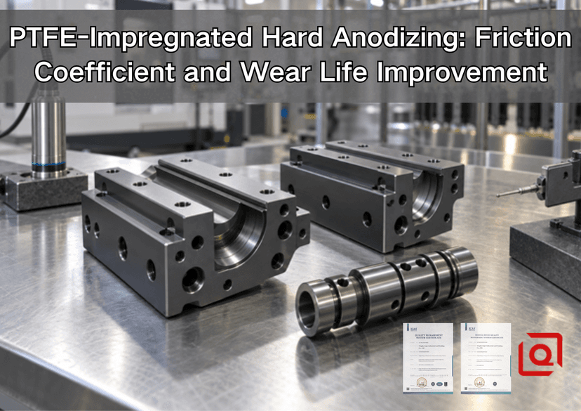
Have you had a coated aluminum slide pass final inspection and still stick after a night at rest? A familiar response is to ask for a “slipperier” hardcoat. That may be the right direction, but first pin down the complaint. Was the force high only on the first move, or throughout the stroke? Did the mating block lose material? Is there gray powder in the rail? Those answers decide what a PTFE-impregnated hard anodic coating needs to prove.
1. Start With the Contact, Not the Coating Name
On a drawing review, I would put the coated track and its mating part in one sketch. Note the material of each, the load, stroke and longest dwell. A static breakaway test after that dwell tells more about morning stick-slip than an average running coefficient measured after fifty cycles. If the mechanism makes short reversals, use that motion in the test. A circular pin-on-disc result may still be useful for screening, but it cannot stand in for a reversing guide without validation.
The coating itself has two jobs. The oxide is the hard load-bearing skin; the softer aluminum sits below it. PTFE lowers shear at the contact face. That combination may reduce galling and the force spikes that make a drive chatter. It does not set one permanent coefficient of friction. Change the follower from POM to steel, let dust accumulate, or add cleaning fluid, and the contact behaves differently. The supplier’s published number belongs in a shortlist, not automatically on the drawing.
SAE AMS2482 covers both impregnated and codeposited PTFE hardcoat. NASA/JSC PRC-5011 Rev. B adds a useful check for the buyer: name the processor and process, then state the film thickness and how it will be verified. Without those, two lots can carry the same finish name while following different routes. This article works through the drawing, tests and inspection needed to make the finish repeatable on a machined part.
2. Why Type III Hardcoat Can Still Stick
Suppose a guide returns from service with a polished rail and a damaged follower. Before changing the coating, put the follower beside the rail and compare the two wear paths. Does the scar stay on one edge? Could the assembly be tilted? Has grit collected at the reversal point? A lower coefficient for the rail alone might not help if the polymer shoe is being cut by a narrow peak.
The review can be recorded in three lines rather than a vague note saying “worn coating.”
|
Observed clue |
Check next |
Possible mechanism |
|
Smeared material on the opposite face |
Confirm both alloys and look for transfer |
Adhesion or galling |
|
Fine cuts plus loose particles |
Find the particle source and inspect both surfaces |
Abrasion |
|
Start-up load above running load |
Dwell-matched force trace |
Stick-slip |
PTFE and oxide do different jobs in the same finish. The track texture still matters to the follower. Do not quietly swap in a sprayed film: its build and edge coverage require different drawing allowances. If the drawing simply says “Teflon anodize,” revise it before ordering.
For a clean machine that cannot use grease, run a pilot with the real follower. Include starts, stops, the longest idle period and any cleaning fluid. If drive force or debris crosses the agreed limit, stop the trial. “Self-lubricating” describes a qualified operating window, not an unlimited service promise.
3. Friction Coefficient: Measure the Pair
A supplier sheet may quote dry sliding COF near 0.05 to 0.15, or a processor trial may show roughly half the static friction of ordinary hardcoat against plastic. I would keep those figures, but not copy either onto a drawing yet. First ask: what touched the coating? A steel pin can give a clean laboratory trace while the real part uses a POM block, a seal or another anodized face. The pressure, stroke and humidity may differ too.
For a slide that jerks on Monday morning, I would ask the test house for two readings. Record the first force peak after a defined dwell, then the running force over the next strokes. Report them separately. An average that blends both can make the complaint disappear on paper. For a valve with quick reversals, set the rig to reverse. For a coated bore, use the production seal compound.
The RFQ table should make those choices visible before anyone quotes the coating.
|
Item |
Record on the drawing or test plan |
Why a buyer needs it |
|
Mating face |
Grade, hardness, coating and roughness |
It is part of the COF result |
|
Contact load |
Normal force or contact pressure |
A different load changes the track |
|
Motion |
Speed, stroke, direction changes and dwell |
Start-up and running values diverge |
|
Surroundings |
Temperature, humidity, fluid and dirt |
The transfer film sees the environment |
|
Report |
Static peak, running average and wear limit |
One figure cannot answer every failure |
Put bare aluminum and ordinary Type III coupons in the same rig for comparison. Keep the force trace, photographs of both faces and the machine’s pass/fail limit beside the COF figure. That package travels much better from prototype to a repeat order.
4. Wear Life: Define the Finish Line
How many cycles is “long life”? If a slide still moves after the trial but its drive current has doubled, the test has not passed just because the coating remains dark. Decide what stops the machine in service: breakaway force, backlash, leakage, loss from the follower, a track scar, or visible aluminum. Write that limit down before ordering samples.
A flat coupon is a sensible first filter. Make the coupons from the production alloy and temper, then run the same counterface, load and cleaning routine across bare aluminum, ordinary hardcoat and the PTFE version. The comparison tells you whether the finish deserves a part-level trial. Move to the real feature next, then to a pilot assembly.
Use the standards for the measurement they actually cover.
|
Reference |
Use in this project |
|
Taber abrasion, hardcoat |
|
|
Eddy-current film thickness |
A separate reversing test still needs the actual follower. Where was the thickness probe placed? An outer boss may be easy to reach but miss the working channel.
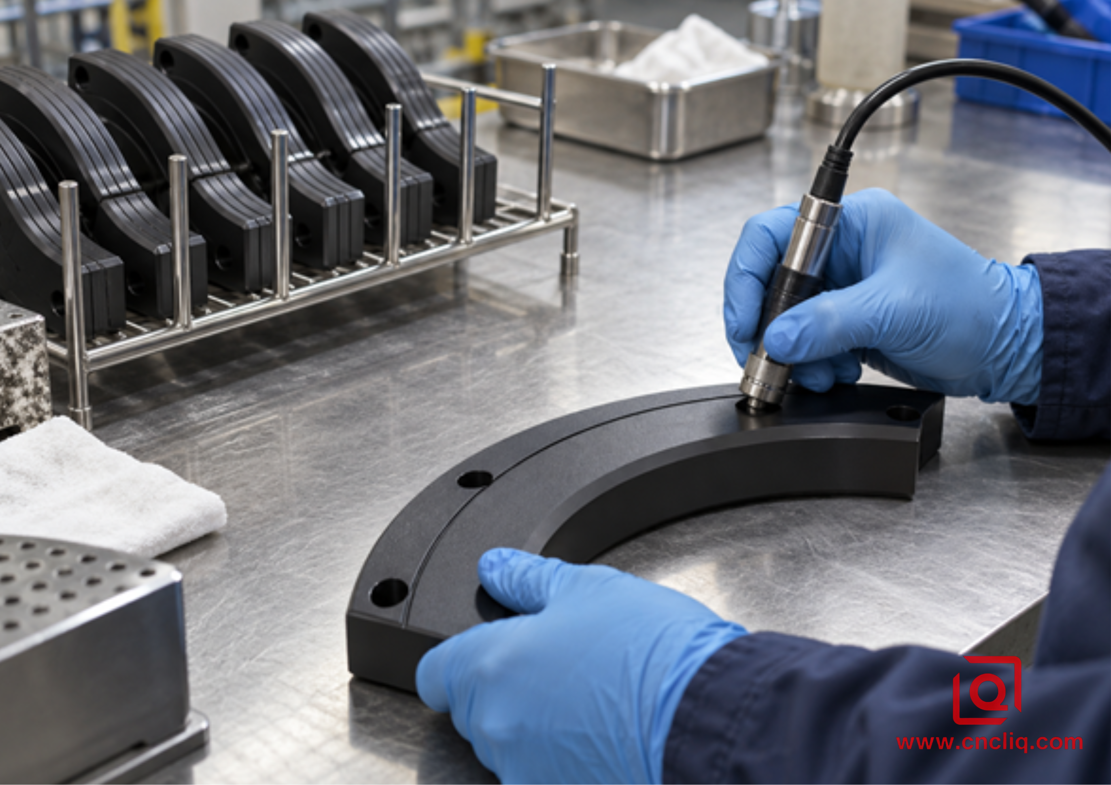
Inline image: eddy-current thickness inspection on a curved hard-anodized guide
At each stop, inspect both mating parts. Keep photographs with scale, the force trace and any measured dimensional change. For a channel the probe cannot reach, ask for an agreed witness and a first-article section to establish the relationship.
5. Film Thickness, Growth and the Finished Fit
A drawing says the shaft should be 12.000 mm with a tolerance of ±0.010 mm after PTFE hardcoat. The shop made it 12.000 mm before coating. Those are not the same stage.
If the coating process adds 50 microns of oxide and half of that grows outward, the shaft could end up 50 microns bigger in diameter. Enough to lose the fit. This estimate isn’t a machining rule. You must check the alloy, the coating process, and the thickness tolerance first. This shows why you can’t just leave the size to the coating vendor to guess.
The numbers in NASA/JSC PRC-5011 Rev. B are worth keeping near the drawing, with one caution: they are specification figures, not a blanket thickness choice.
|
PRC-5011/AMS2482 figure |
Inches |
Metric equivalent |
|
Default |
0.0020 ± 0.0005 |
50.8 ± 12.7 µm |
|
Specified range |
0.0011 to 0.003 |
27.9 to 76.2 µm |
The same document describes approximately half outward growth and half penetration into the aluminum per surface. Check the processor’s own allowance before setting a machine-to dimension. Our Type III hardcoat DFM guide covers allowance and masking, while the film-thickness and tight-assembly guide looks closely at shafts, bores and threads.
I’d add a small section view next to the dimension callout. Show the shaft, the mating hole, the masked thread, the wear track and where a gauge can actually make contact. Then ask the processor a question: can the specified coating be applied on the working track, or only on the easy-to-reach outer diameter? A measurement from the boss might look fine but it won’t tell you what’s happening where the part actually fails.
The same care should go into surface finish. If a pre-coat tool mark crosses the sliding track, PTFE will not make the geometry flat. Give the machinist a pre-coat roughness requirement and ask how the finished track will be checked. Radius the working edges and show rack-contact areas on the print. A tight thread or press fit may need masking rather than an optimistic coating allowance.
6. Alloy Choice and Geometry: Start With the Drawing
Suppose an RFQ calls for 7075-T6 because the old steel link is being lightened. The first question is not whether 7075 can turn black in the tank. Record the load path and minimum section next to the coating note. Trial the production temper, not a convenient sample alloy.
The decision belongs to the part, not to a general ranking of alloys. I would show the buyer a short comparison rather than promise the same appearance on both grades. Our 6061, 7075 and 5052 machining guide expands on the material tradeoff.
|
Drawing question |
6061-T6 route |
7075-T6 route |
|
Base strength |
Check against the load case |
Often selected for higher strength |
|
Coating trial |
Use production temper and preparation |
Use production temper and preparation |
|
Critical surface |
Name wear track and thickness location |
Name wear track and thickness location |
The NASA/JSC PRC-5011 material screen is specific enough to put in the DFM notes.
|
PRC-5011 condition |
Response |
|
Normal alloy limits |
Copper below 5%; silicon below 8%; copper plus silicon below 8% |
|
Above the silicon limit |
Coordinate with the responsible materials engineer |
Now turn the model. Mark electrolyte access, thin walls, masked threads and rack contact on that view. A section view with those four answers will prevent more trouble than a cosmetic color note. For a tight fit, decide machine-to size and masking before metal is cut. If finish appearance matters too, inspect the cosmetic face separately from the working surface. Our OEM aluminum finishing guide helps compare alternative routes before one is frozen into the drawing.
7. A Shop-Floor Route for Repeatable Parts
A coating lot cannot repair an undocumented machining lot. Who signs off each handoff? Use the traveler to make that visible.
1. At DFM, pair the contact materials and mark finished datums, wear tracks, radii, drain paths and rack contact.
2. Machine to an approved pre-coat size. Keep the record that links this size to the final coated tolerance.
3. Deburr and clean without changing the wear track by uncontrolled hand polishing or trapped blast media.
4. Mask threads, bearing seats, seal lands and electrical contacts where the film cannot be accepted.
5. Run the agreed Type III and PTFE process. Record the processor and route; a trade name alone is not a control plan.
6. Coating inspection: film readings at the drawing locations, followed by finished-size checks.
7. Inspect roughness and appearance on the working track, and run the agreed friction or wear test on representative material.
8. Assemble a pilot. Keep the material heat, machining revision, coating lot and final report together.
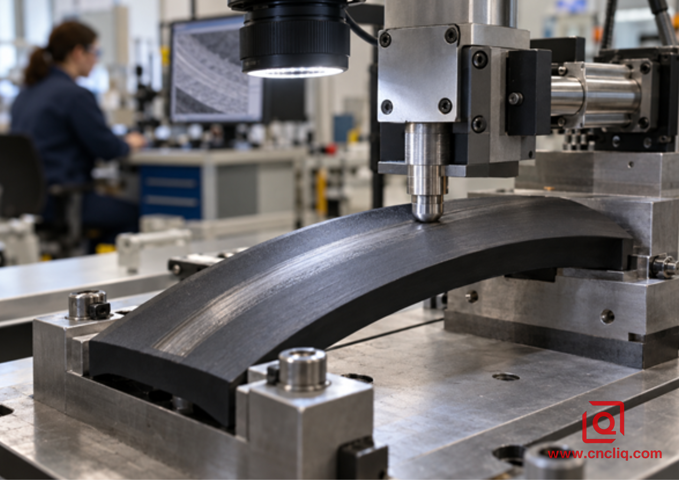
Inline image: reciprocating wear test on a curved PTFE-hardcoat rail
A skipped masking decision often appears late, when a thread will not assemble or a press fit chips its edge. A skipped test decision appears later still, when a low COF quotation cannot be tied to the actual follower. Compare the quoted part after masking, tests and assembly checks are included, not only the tank price.
8. What to Put in the RFQ
One supplier reads “PTFE anodize, black” and plans a 50 µm film. Another assumes a different build, masks the thread and prices no friction test. Both bids may look reasonable. Use one finish sheet alongside the 2D drawing.
|
RFQ field |
Put this in the package |
|
Base metal |
Alloy, temper, product form, annual volume |
|
Route |
AMS2482 revision, approved processor, impregnated or codeposited PTFE |
|
Film |
Thickness, tolerance, gauge method, probe locations |
|
Fit |
Finished sizes, machine-to sizes, masked threads and seats |
|
Track |
Radii, rack marks, pre-coat and final roughness |
|
Duty |
Follower grade, load, stroke, speed, dwell, fluid and dust |
|
Acceptance |
Static peak, running value, wear or other failure limit |
|
Evidence |
Coupon count, pilot quantity, reports and lot traceability |
If the existing machine jerks on start-up, send the force trace with the CAD package. If the follower sheds particles, send photographs of both faces.
A listed custom hydraulic manifold with CNC machining and anodized surface shows a related machining-and-finishing route. It is not a claim that every manifold has PTFE hardcoat.
9. Anonymized Composite Case: Dry-Running Indexing Cam
This anonymized composite case is illustrative, not a customer-specific life claim.
An automation buyer wants a lighter indexing cam for a clean assembly cell. The current steel cam works, but its moving mass is high. The first 6061-T6 cam receives ordinary Type III hardcoat. Its groove collects dark follower debris; torque rises after the machine idles. The drawing gives the coating name but says nothing about the follower, groove thickness or torque test. The processor’s thickness reading comes from an easy outside face.
The buyer and machining team put the parts back on the bench. They check the follower’s wear line, measure the pre-coat groove finish and add a radius where the track changes direction. The rack contact is moved away from the working groove. The revised package asks for a qualified PTFE-impregnated hardcoat route, a thickness witness correlated with the groove and final dimensional checks on the cam. A reciprocating coupon uses the production follower polymer rather than a convenient steel pin.
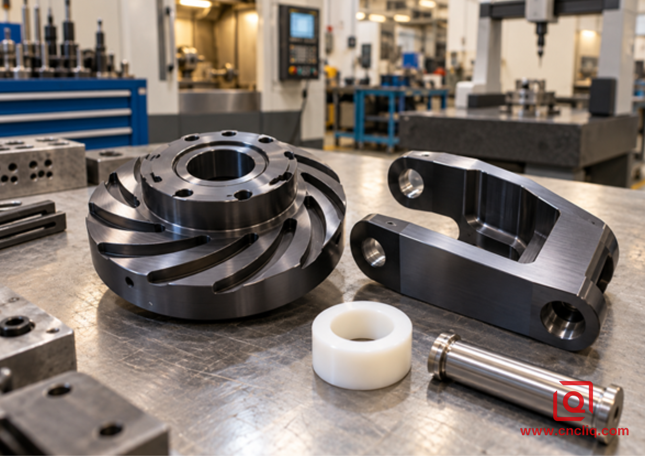
Inline image: hard-anodized indexing cam, yoke, polymer bearing, and mating pin
For the assembly pilot, the buyer chooses a torque band and a planned cycle count before the test starts. The log has separate fields for breakaway torque, running torque, debris, follower wear and exposed aluminum. Crossing either the torque or wear limit stops the trial. If it passes, release is limited to that defined load, motion and environment; a hotter or dustier machine needs another review.
The useful change is not simply “add PTFE.” The drawing now joins geometry, machining allowance, coating route, follower and evidence. That is what makes a repeat order possible.
10. When Another Finish or Bearing Makes More Sense
The coupon passed, but the machine still failed. Before ordering another coating lot, circle the service condition missing from the trial. A small table on the design review sheet keeps the discussion out of vague “better coating” language.
|
Condition |
Check on the part |
Other route to consider |
|
Impact or repeated flexing |
Edge chips, fatigue-critical section |
Materials review or replaceable insert |
|
Deep bore |
Film access and a usable probe site |
Masked bore or separate sleeve |
|
Tight press fit |
Outward growth and assembly damage |
Masking or revised machine-to size |
|
Dirty counterface |
Pin roughness, alignment, trapped grit |
Cleaning, bushing or controlled lubricant |
For appearance and routine corrosion protection, ask whether Type II anodizing is enough. For abrasion without a dry-running requirement, compare a qualified Type III route without PTFE.
11. Five Checks Before Quotation
Where can the thickness gauge touch? Will a rack mark land on the wear track? Can the final report connect the material heat to the coating lot? Those questions often expose a missing drawing note before the first billet is cut.
Send the CAD model, controlled drawing, mating material, load, motion, operating environment and current failure with your inquiry. Liqin’s team can review machine-to sizes, masking, inspection access and a pilot test before pricing a volume run. If a cam, guide, valve or manifold is stopping your line, include a photograph of the worn pair. It gives the engineering review a better start than a request for “slippery black anodize.”
FAQ
1. What coefficient of friction should I put on the drawing?
Not a catalog figure by itself. Use the production mating part and define whether the limit is the first peak or a running value. Keep the force trace and the worn-part inspection in the report. A steel-pin result should not quietly stand in for a POM shoe.
2. Will PTFE hardcoat change the finished dimensions?
Yes, plan around the oxide. The film grows partly into the aluminum and partly outward; opposing coated faces change a shaft or bore size together. The print needs two sizes: metal before coating and part after coating. Add film tolerance, probe sites and masks; confirm the allowance with the processor.
3. Can the part run without grease?
Sometimes. The answer belongs to the pair and duty cycle, not to the word “self-lubricating.” Run the real follower at the expected load and temperature. Include starts, stops, the longest idle period, cleaning fluid and contamination likely in service. Watch both force and wear. If the assembly crosses either limit, dry running has not been qualified.
4. Is 7075-T6 necessary, or will 6061-T6 work?
For a load-carrying link, check fatigue before choosing 7075-T6. A less stressed guide may use 6061-T6. Put the production temper on the coating trial and inspect the working face, not just an easy outer boss. Do not use a coupon from a different alloy as a release result.
5. What should go into an RFQ for this finish?
Send the CAD file and the print that controls inspection. On the print, identify alloy, temper, volume, film, masks and probe locations. Name the follower, load, motion, environment and current failure. If the quote must cover COF or life testing, specify the acceptance limit and sample count.
Summary
PTFE-hardcoat is a useful option when hard oxide, low-shear contact and the mating part are qualified together. Start with the failure, then control film thickness, finished fit, track texture, processor route and the test that reproduces the duty. Send the CAD package and worn-part evidence with the RFQ. A short pilot with clear stop limits is worth more than a catalog COF copied onto the drawing.
Contact Information
Company: Ningbo Liqin Industry Co., Ltd.
Daily customer maintenance & after-sales support:service@shturl. zhuwanying@cncliq.com
New inquiry, quotation & order discussion:business@shturl. zhouli@chinaliqin.com
Hotline: +86 18757148656
Disclaimer
All technical articles, material specifications, machining recommendations, and surface treatment details published on this blog are for informational and reference purposes only. Please note that general blog insights do not replace signed technical agreements. Because custom parts vary by material heat numbers, machine calibrations, and specific tolerances, binding quality specs are governed solely by your approved CAD drawings, signed contracts, and formal quality plans.
All customer case studies featured on this blog have been thoroughly anonymized and sanitized. The performance metrics, manufacturing workflows, and imagery displayed serve solely to demonstrate our custom machining capabilities and do not represent a single universal standard for all orders.
Liqin Manufacturing Team
Built on 18 years of precision engineering experience, Ningbo Liqin Industry manufactures high-tolerance metal components for demanding global markets. We operate out of a 6,500 m² production hub equipped with over 150 machines, running 4-axis and 5-axis CNC machining, mill-turn machining, cold extrusion, and pressure die casting under one roof. This setup allows us to manage projects seamlessly, taking parts from initial CAD concepts directly to finalized shipments.
We handle quality control with zero compromise. We treat tight tolerances with the engineering discipline they require. Backed by ISO 9001, ISO 13485, and IATF 16949 certifications, our QA engineers run strict IPQC, FQC, and OQC checks on every single production batch. From CMM dimensional mapping and optical profiling to hardness and salt-spray testing, we validate your critical specs upfront—so you receive drop-in ready components with zero assembly headaches or costly line stoppages. On top of manufacturing, you can rely on us for two-hour response times on new RFQs, direct support for prototype sampling, and smooth export shipping across Europe, North America, Asia, and Oceania.
Welcome your inquiries and samples. Visit our website or contact us directly for a competitive quote!
