 English




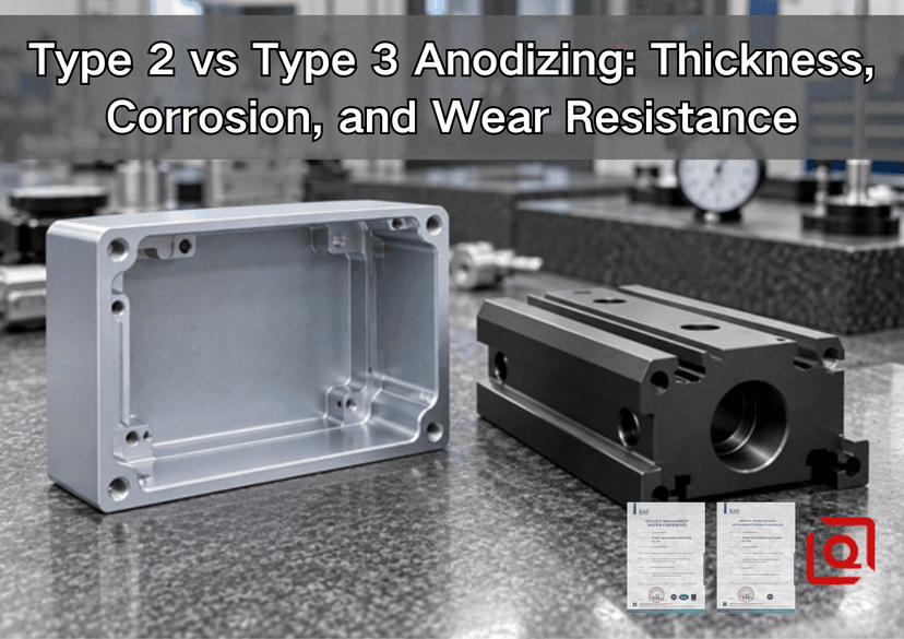
A black anodize sample can look perfect on the approval table. Then production arrives, the shaft stops at the mouth of the bore, and a finish decision suddenly becomes an assembly problem. If that sounds familiar, this guide is for you. This guide turns the specification into practical shop-floor choices. You will see what the 2 processes actually change, why “harder” does not automatically mean “better,” and what a machining supplier needs before it can quote an anodized aluminum part responsibly.
On the shop floor, we usually start with Type II when a buyer wants color and routine environmental protection. We move toward Type III when the surface itself has to work: a rail rubs, a piston travels, or abrasive dust keeps finding the same contact patch. The label is only the beginning. Alloy chemistry, sealing, film thickness, rack contact, masking and the moment at which dimensions are inspected decide whether the finished part actually assembles.
Fast selection rule: choose Type II when appearance and sealed corrosion protection lead. Choose Type III when an aluminum surface is a functional wear interface and the drawing can accommodate a thicker, darker, less color-consistent oxide. If the part needs both, specify the requirement by surface instead of applying 1 finish blindly to the entire component.
1. Type II vs Type III at a Glance
|
Engineering factor |
Type II sulfuric anodizing |
Type III hardcoat anodizing |
|
Primary purpose |
General corrosion protection, appearance, dyeing, paint or adhesive base |
Abrasion resistance, sliding wear, functional hard surface, qualified electrical isolation |
|
Common purchase thickness |
Often 5–25 µm; put the actual range on the drawing or purchase order |
MIL-PRF-8625 default nominal is 0.002 in (50.8 µm) unless another thickness is specified; its typical range is roughly 12.7–114.3 µm |
|
Color |
Clear/undyed or broad dyed colors; best route for cosmetic control |
Natural gray, bronze, olive, brown, or near-black; black dye is possible, but bright color matching is not its strength |
|
Sealing |
Normally sealed unless the order says otherwise |
Often unsealed for maximum abrasion resistance; sealing may be required when corrosion leads |
|
Dimensional effect |
Modest but important on threads, dowel holes, seals, and close fits |
Substantial; machining and inspection must account for growth on every coated surface |
|
Best-fit parts |
Enclosures, panels, brackets, housings, handles, visible hardware |
Valve bodies, guides, cams, pistons, sliding blocks, actuator parts, hinges |
MIL-PRF-8625 defines Type II by process and coating weight, not by 1 universal mandatory thickness band. “Type II, black” is therefore incomplete when thickness matters. Type III is different: unless the contract, drawing, or purchase order says otherwise, the specification sets a nominal 0.002 in coating. Class does not mean performance level: Class 1 is undyed and Class 2 is dyed.
2. What Actually Changes in the Anodizing Tank?
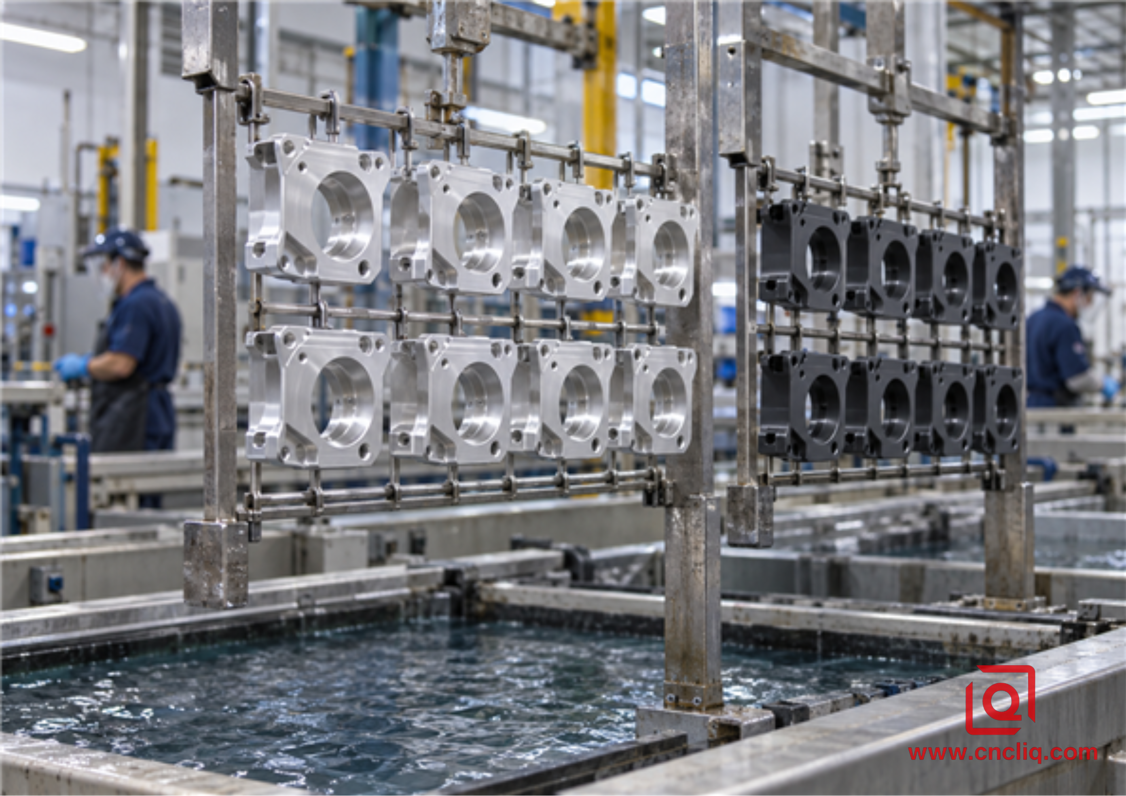
Production control starts with alloy segregation, cleaning, racking, electrical contact, and stable bath conditions—not with color selection.
Both types convert the aluminum surface into aluminum oxide. This is not a loose skin sprayed over the component. The part becomes the anode in an electrolytic cell, oxygen reacts at the surface, and a porous oxide grows partly into the base metal and partly above the original boundary.
Type II uses a sulfuric acid bath under conditions selected for a useful balance of pore structure, corrosion protection, dye response, and production efficiency. Type III builds a heavier, denser coating under more demanding controls. In practice that normally means a colder bath, higher current density, strong agitation, reliable electrical contact, and enough cooling capacity to prevent local burning. These requirements explain its higher price and why large surface areas or deep recesses demand thoughtful racking.
The visible result still depends on what entered the tank. Put a 6061 cover, a 7075 bracket and a silicon-rich casting on the same rack and the colors can still come back noticeably different. We also expect weld filler, heat-affected areas and grain flow to show through; those clues belong to the metal, not to a careless dye operator. Anodizing follows the substrate; it does not hide scratches, cutter marks, or inconsistent blasting. For a wider process view, see Liqin’s OEM guide to finishing CNC-milled aluminum.
3. Thickness and the Tolerance Trap
A commonly ordered Type II layer might be 10–15 µm. A functional Type III layer may be 40–60 µm. The full thickness is not simply added outside. MIL-PRF-8625 design guidance says an outward increase equal to about one-half of coating thickness can be expected on each coated surface. The familiar half-in, half-out rule is where we begin the allowance calculation. It is not where inspection ends. A real first article tells us what that alloy, etch and rack position did to that feature.
Four dimensions I would challenge before release:
- A 20.000 mm journal receiving 50 µm of hardcoat will not stay at 20.000 mm. Using the half-outward estimate, allow about 25 µm on each side, then prove the result on a first article.
- A 12.000 mm bore coated to the same 50 µm can close by about 50 µm across its diameter. If the shaft fit matters, oversize the bore before finishing or mask it.
- An M3 internal thread is too small to treat casually. Oxide on both flanks changes how the fastener enters, and coating inside a deep thread can be uneven. Decide on masking and the finished gauge during DFM.
- A 12 µm Type II layer on an enclosure moves a single face only a few microns, but 2 opposed coated faces can still tighten a connector opening or gasket pocket.
There is another number in the stack-up: the etch takes metal away before the oxide appears. I like to see a before-and-after pair on the control sheet. The first reading belongs to the machined feature; the second belongs to the finished part. Without that pair, a tight dowel hole or seal groove can miss size and nobody can tell whether machining, etching or growth caused it.
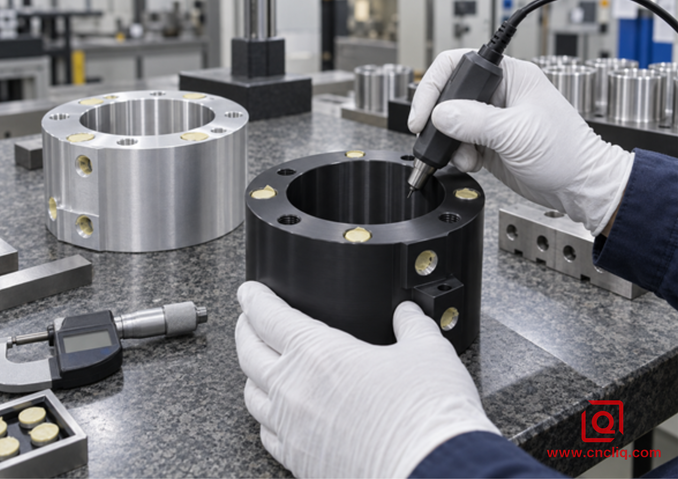
The probe is only one part of the check. We also want the mating gauge, the masking boundary and the intended rack location in the same conversation.
For Type III, MIL-PRF-8625 points inspectors to ASTM B244 or ASTM E376. Do not stop after 1 convenient probe touch: the reported thickness is based on at least 8 readings. If buyer and supplier still disagree, a calibrated metallographic cross-section is the referee. Curves, edges and different base-metal conductivity can all nudge an eddy-current reading, so the drawing should name the places that count. Put measurement locations on the control plan instead of reading a convenient flat coupon and assuming a blind bore matches.
Liqin’s Type III hardcoat anodizing DFM guide covers allowance, masking, and drawing review in more depth. The verified custom CNC-machined aluminum manifold is a relevant product example because port threads, sealing faces, intersecting passages, and precision bores make finishing inseparable from machining.
4. Corrosion Resistance: Thickness Is Only Part of the Answer
A dark, heavy hardcoat can look reassuring and still corrode first at a damaged corner. In damp service we look past the type number and ask whether the oxide is continuous, whether it was sealed, what alloy sits underneath, and whether stainless hardware or trapped water creates a local weak point.
The standard check is specific. MIL-PRF-8625F with Amendment 2 sends sealed specimens into ASTM B117 salt fog made with a 5% solution. They remain there for 336 hours, and acceptance is based on the permitted number and size of pits—not on whether the panel still looks showroom-new. Type II is sealed unless otherwise specified. Type III used for maximum abrasion should remain unsealed; when exterior corrosion is more important and reduced abrasion is acceptable, the order can require sealing.
- For a cosmetic outdoor housing, sealed Type II on a suitable wrought alloy may be the more predictable choice.
- For a dry sliding guide, unsealed Type III may protect the wear surface better.
- For a hard-wearing part in wet service, the drawing must resolve the wear-versus-seal tradeoff.
- For galvanic exposure, isolate dissimilar metals where necessary and maintain drainage. Anodizing cannot rescue a poor joint design.
Salt spray is a process qualification tool, not a direct field-life clock. A 336-hour result does not mean 336 hours outdoors. Put any required duration, pit limit, and coupon alloy into the RFQ and quality plan.
5. Wear Resistance: Where Type III Earns Its Place
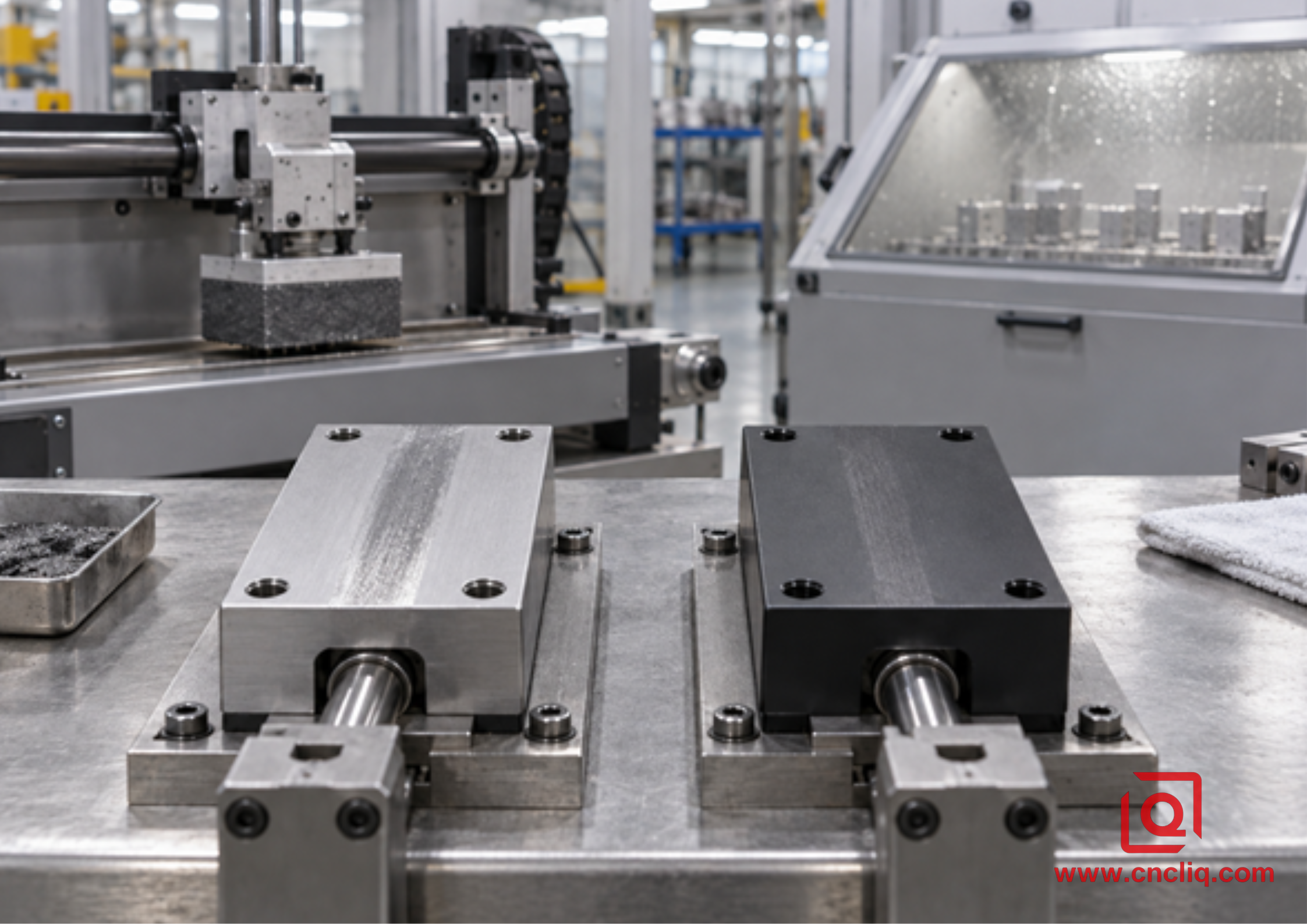
Wear depends on coating structure, counterface, load, lubrication, sealing, and test method—not color alone.
The wear test is equally concrete. Under the MIL-PRF-8625 route, an unsealed Type III panel runs ASTM D4060 with CS-17 wheels. Each wheel carries 1,000 g and turns at 70 rpm; the run lasts 10,000 cycles. Afterward, weight loss is converted to a wear index. The ceiling is 3.5 mg per 1,000 cycles for alloys at or above 2% copper, and 1.5 mg for the other alloys. Those numbers are more useful than “extremely durable” because they identify a method and acceptance threshold.
Do not turn that test into a universal service life. A seal, dusty guide rail, hand-held enclosure, and bearing seat impose different pressure, debris, lubrication, temperature, and counterface. Type III generally outlasts Type II under abrasion, yet more thickness is not always better. The specification notes that abrasion resistance can decrease near 3 mils and does not automatically rise with thickness. It also warns that sealing reduces Type III wear resistance.
6. Alloy, Color, and Surface Finish
6061-T6 is the material we can normally take through machining and anodizing without much cosmetic drama. A 7075-T651 part is a different conversation: its strength may suit the structure, but natural hardcoat often runs darker. Copper-rich 2xxx stock, zinc-rich 7xxx stock and castings deserve an early finish trial. Silicon-rich 360, 380 and 383 castings may turn gray or mottled, and building a thick hardcoat on them is difficult. MIL-PRF-8625 also restricts Type III above specified nominal copper and silicon contents unless approval is obtained.
For color matching, control alloy and temper, visible-part material lot, machining or blasting direction, approved limit samples, and rack-mark zones. “Black anodize” alone is not an objective cosmetic standard. Type II is normally better for vivid colors. Type III can be dyed, especially black, but its natural dark tone limits the result. A part may pass thickness and wear while missing an unspoken expectation for perfect jet-black uniformity.
Thin walls, sharp edges, interrupted surfaces, and mixed cast/machined zones can also create variation. Liqin’s custom aluminum OEM parts guide explains why alloy, CNC strategy, and finish should be reviewed together.
7. Anonymous Customer Case: A Sliding Manifold Carrier
Case status: This is a fictionalized, anonymized composite based on common custom-machining conditions. It is not claimed as 1 identifiable order.
An automation buyer requested 6061-T6 manifold carriers containing pneumatic passages, an H7 guide bore, M4 threads, 2 sealing lands, and an external rail sliding against a polymer wear pad. The first drawing said “black hard anodize” everywhere but omitted thickness, sealing, masking, and the dimensional stage.
A nominal 50 µm Type III layer could close the guide bore by about 50 µm using the half-outward planning rule. The customer needed long rail life, not hardcoat inside ports or on gasket faces. The revised route hardcoated only the exposed rail and outer wear surfaces. The bore, threads, sealing lands, and grounding point were masked. The rail received a machining allowance and controlled edge radius. Inspection covered functional width, bore gauge, coating thickness at agreed locations, and rack-mark zone. A prototype batch was assembled and cycled before release.
Selective hardcoat added masking work, but it avoided tight bores and unnecessary coating. Every supplier could quote the same finish scope and inspection package, making price comparison more meaningful.
8. Put the Requirement on the Drawing and RFQ
|
RFQ field |
State this |
Why it matters |
|
Material |
Alloy, temper, lot control |
Affects growth, color, corrosion, and achievable hardcoat |
|
Type/class |
Type II or III; Class 1 or 2 |
Separates process from color |
|
Thickness |
Target, tolerance, locations |
Controls fit and supplier assumptions |
|
Color/texture |
Color, blast/etch route, limit samples |
Makes appearance measurable |
|
Sealing |
Required, prohibited, or proposed |
Resolves corrosion versus wear |
|
Masking |
Threads, bores, contacts, seals, rack marks |
Protects functional interfaces |
|
Dimensions |
Pre- and post-finish dimensions and gauges |
Clarifies acceptance stage |
|
Records |
Thickness, salt spray, abrasion, color, FAI, CMM, material certificate |
Matches evidence to risk |
Type II example: “Anodize per MIL-PRF-8625, Type II, Class 2, black; 10–15 µm; seal required; mask identified threads and grounding pads; finished dimensions apply after coating; color per approved limit sample.”
Type III example: “Hard anodize per MIL-PRF-8625, Type III, Class 1; 50 µm nominal; unsealed for wear; mask bores and sealing faces; measure thickness at A, B, and C; marked FAI dimensions apply after coating.” These examples are not universal instructions; drawing authority must confirm the final callout.
Planning an anodized aluminum part? Send the 2D drawing, 3D model, alloy and temper, annual quantity, mating dimensions, environment, color, and the surfaces that slide, seal, conduct electricity, or stay uncoated. Liqin can review allowance, masking, inspection, and finish selection before quotation. Submit your project for a manufacturing review and competitive quote.
8.1 First-Article Checks That Matter
A first article should enter the real assembly, not just a plastic sample bag. Try the shaft in its bore, pass the seal over its edge, and run the specified gauges through finished threads. Deep pockets and narrow slots may not build the same oxide as an open face, so measure the locations that affect function.
Record a critical feature before and after anodizing. That pair separates machining error, etch removal, and coating growth far better than a single finished reading. For appearance, compare dry parts to signed limit samples under agreed lighting and orientation. Directional blasting can make 2 matching panels look different when the light moves.
Quick receiving check
- Confirm part number, drawing revision, alloy, and temper.
- Inspect rack marks and masking boundaries before handling.
- Measure the agreed external feature and critical bore.
- Use functional gauges on coated threads; never force a tight fastener.
- Match color to approved limits, not memory or a web photograph.
- Record concerns by feature location and lot number.
9. Nine Checks Before I Release the Drawing
1. Name the failure in plain language. Write down what you are trying to stop: white corrosion around a screw, a rail polishing through, a color mismatch, lost insulation, or a shaft that binds. Different failures point to different controls.
2. Confirm alloy and temper. Do not approve the finish before confirming what aluminum enters the bath.
3. Separate cosmetic and functional surfaces. 1 part can legitimately need different treatment or masking zones.
4. Set thickness from the requirement. More oxide is not automatically better, especially near tight fits or fatigue-critical geometry.
5. Choose sealing deliberately. Type II is usually sealed; Type III wear surfaces may need to remain unsealed.
6. Apply a pre-machining allowance. Review external sizes, bores, slots, threads, dovetails, gasket grooves, and press fits.
7. Control appearance. Define alloy lot, pre-treatment, rack-mark location, shade range, and inspection lighting for visible parts.
8. Specify evidence. Ask for only the reports that prove your critical requirements, using named test methods where appropriate.
9. Approve a first article. Measure and assemble the coated component before releasing volume production.
FAQ
1. Does Type III automatically last longer in a corrosive environment?
Not automatically. I would rather have a sound, sealed Type II film on the right alloy than a chipped or poorly sealed hardcoat. For an outdoor cover, the first option can be entirely sensible. On a rubbing surface, the hardcoat may win because wear is the governing failure. Put the environment, seal condition, and acceptance test on the order; the Roman numeral by itself cannot predict field life.
2. How much does Type III anodizing change a bore diameter?
As a planning rule, about half the coating thickness grows outward from each coated wall. A 50 µm Type III layer may therefore reduce a fully coated bore diameter by about 50 µm in total. Etching, alloy response, geometry, and process variation can change the result, so use the estimate for DFM, then confirm it with first-article measurements at the actual feature.
3. Can Type III hardcoat be dyed black?
Yes, Type III can be supplied as Class 2 dyed coating, and black is common, but the natural oxide is already gray, bronze, olive, brown, or near-black depending on alloy and thickness. That base tone limits bright colors and can make exact lot-to-lot cosmetic matching difficult. If uniform color is the main requirement and severe sliding wear is absent, Type II is normally easier to control.
4. Do I need to mask every threaded hole?
No. A roomy thread in light Type II may work perfectly well when coated, while a small hardcoated blind thread can become troublesome. Look at size, engagement length, exposure and whether the joint must conduct electricity. Circle the threads that stay bare, then agree on the finished check: plug gauge, real fastener, or pitch-diameter measurement. That decision belongs on the drawing, not in an email sent after parts reach the tank.
5. What should go into the RFQ package?
Give the supplier the 2D drawing, 3D model, alloy/temper and quantity first. Add the finish type, class, thickness, color and seal choice. A marked-up PDF showing bare areas, acceptable rack contacts and post-finish dimensions is worth more than a long unstructured email. Include the mating-part details and say which faces rub, seal, ground or touch fluid. Finally, list the reports you truly need. With that package, the quote covers the same job you expect to receive.
Summary
If the part mainly needs color and routine protection, start the conversation with Type II. If a face carries sliding or abrasive contact, discuss Type III. Then finish the job properly: name the alloy, film thickness, seal choice, masked zones, dimensional stage and inspection evidence. A few clear notes on the drawing are cheaper than sorting coated parts beside a stopped assembly line.
Where These Numbers Came From
The main reference is MIL-PRF-8625F with Amendment 2, dated November 23, 2020. It is where I checked the type definitions, default Type III thickness, sealing choices, dimensional-growth note and acceptance language.
That specification sends the corrosion work to ASTM B117 and sets a 336-hour salt-fog exposure for the applicable panels. Its hardcoat abrasion route points to ASTM D4060 and then adds the wheel, load, speed, cycle and wear-index limits used above. For thickness, it references ASTM B244 or ASTM E376. Listing the methods matters: a number without its test setup is easy to misunderstand.
Contact Information
Company: Ningbo Liqin Industry Co., Ltd.
Daily customer maintenance & after-sales support:service@shturl. zhuwanying@cncliq.com
New inquiry, quotation & order discussion:business@shturl. zhouli@chinaliqin.com
Hotline: +86 18757148656
Disclaimer
All technical articles, material specifications, machining recommendations, and surface treatment details published on this blog are for informational and reference purposes only. Please note that general blog insights do not replace signed technical agreements. Because custom parts vary by material heat numbers, machine calibrations, and specific tolerances, binding quality specs are governed solely by your approved CAD drawings, signed contracts, and formal quality plans.
All customer case studies featured on this blog have been thoroughly anonymized and sanitized. The performance metrics, manufacturing workflows, and imagery displayed serve solely to demonstrate our custom machining capabilities and do not represent a single universal standard for all orders.
Liqin Manufacturing Team
Built on 18 years of precision engineering experience, Ningbo Liqin Industry manufactures high-tolerance metal components for demanding global markets. We operate out of a 6,500 m² production hub equipped with over 150 machines, running 4-axis and 5-axis CNC machining, mill-turn machining, cold extrusion, and pressure die casting under 1 roof. This setup allows us to manage projects seamlessly, taking parts from initial CAD concepts directly to finalized shipments.
We handle quality control with zero compromise. We treat tight tolerances with the engineering discipline they require. Backed by ISO 9001, ISO 13485, and IATF 16949 certifications, our QA engineers run strict IPQC, FQC, and OQC checks on every single production batch. From CMM dimensional mapping and optical profiling to hardness and salt-spray testing, we validate your critical specs upfront—so you receive drop-in ready components with zero assembly headaches or costly line stoppages. On top of manufacturing, you can rely on us for two-hour response times on new RFQs, direct support for prototype sampling, and smooth export shipping across Europe, North America, Asia, and Oceania.
Welcome your inquiries and samples. Visit our website or contact us directly for a competitive quote!
