 English




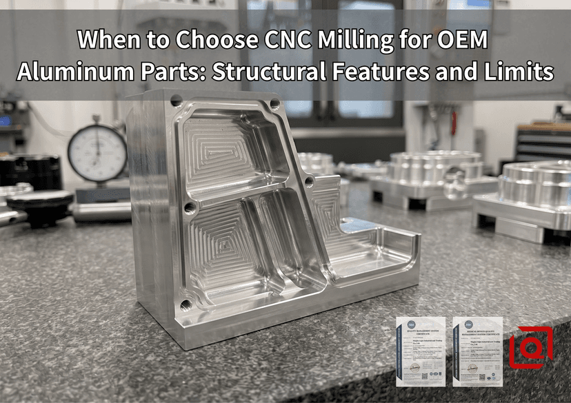
Draft angles look tidy on a CAD monitor. Then your die casting shop ships the first trial parts, and you find gas porosity right along the face where an M4 blind hole needs tapping. Or your extrusion vendor calls to report that an uneven profile is twisting off the cooling table like a dried peel.
That is usually the exact moment custom mechanical jobs head straight to the CNC milling bay.
Choosing billet over casting is rarely about whether a spindle can push a tool through aluminum. Modern machining centers chew metal all day. The real decision hinges on part geometry, stiffness targets, and pressure-tightness needs. Hogging parts from rolled 6061-T6 plate or forged 7075 blocks cuts out shrinkage voids, gas pockets, and slag inclusions before a single cutter flute touches raw stock.
Here is what happens on the shop floor when cutter physics, clamping pressure, and part geometry run into each other.
1. Geometry That Demands Billet Over Cast Metal
Foundries and extrusion plants hate uneven wall thickness. Molten aluminum shrinks as it cools inside steel tools. That thermal drop pulls sink pockets into heavy sections and traps air blisters right next to thin cooling ribs. Extrusions avoid some of those voids, but they trap your design inside a fixed profile along a single straight axis.
CNC milling cuts solid billet without fighting cooling shrinkage.
+-------------------------------------------------------------------------+
|                  GEOMETRIC FEATURE ROUTING GUIDE                        |
+------------------------------------+------------------------------------+
| OPTIMAL FOR CNC MILLING            | POOR FIT FOR CNC (RETHINK DFM)     |
+------------------------------------+------------------------------------+
| Deep, pocketed rib networks        | Sharp square internal corners      |
| Stepped multi-plane sealing faces  | High aspect-ratio thin webs (>10:1)|
| Off-axis bore patterns             | Curved undercut cavities (blind)   |
| Asymmetric wall thicknesses        | Extremely deep micro-channels      |
+------------------------------------+------------------------------------+
Deep Pockets and Stiffening Ribs
When an optical mounting base or an airborne chassis needs stiffness without dead weight, designers scoop away metal from solid plate. What remains is an integrated web of thin ribs surrounding deep pockets.
A foundry mold struggles to push molten metal across tall, narrow gaps. The metal chills early, starving rib tips or pulling the floor out of flat as it shrinks. A rigid milling spindle running dynamic toolpaths chews out those deep pockets cleanly, leaving high strength without hidden cavities.
Still, shop floor limits apply once pocket depths drop past an inch:
-
Tool Overhang Deflection: When an end mill sticks out more than three to four times its shank diameter, cutting loads push the tip sideways. The cutter squeals, chipping flutes and leaving washboard chatter across the pocket floor.
-
Vertex Engagement Spikes: If an inside corner radius matches the cutter radius, tool contact area jumps abruptly. The tool pulls itself straight into the stock, jumps off track, and gouges the wall. Always draft corner radii slightly larger than the planned cutter radius so the tool rolls around the bend smoothly.
Stepped Datum Planes and O-Ring Paths
Multi-axis sensor housings often carry three or four mounting faces, O-ring tracks, and dowel pin holes that must stay square within fractions of a hair.
Steel casting dies expand, wear, and shift after thousands of shots. Die slides develop play. That drift forces you to load the raw casting into a CNC fixture anyway just to true up critical faces. For short and mid-sized runs, skipping the mold and cutting everything directly from a solid block on a 5-axis table saves weeks of fixture work and avoids mismatched tool steps.
2. Shop Floor Physics: How Cutters Push Back
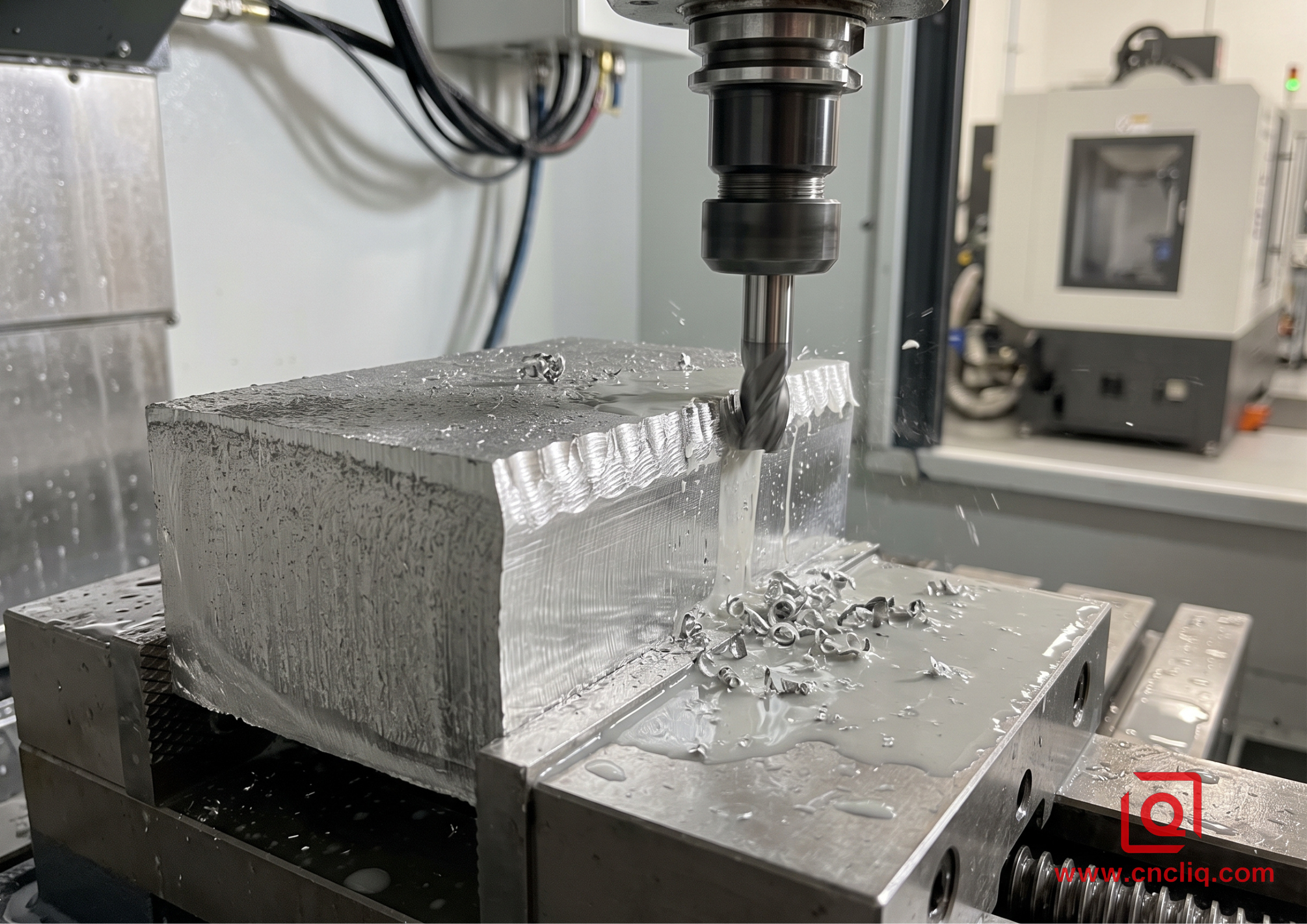
Milling aluminum is not an open pass to machine whatever lines you put into CAD. Solid carbide end mills spin fast, run hot, push sideways loads against thin webs, and throw out chip piles that need room to clear.
The Thin-Wall Threshold
Shave a freestanding vertical rib too thin, and the cutting flutes push the aluminum away on every rotation. The wall hums like a tuning fork. The surface turns rough and scalloped, and the top lip curls the second you loosen the vice.
       WALL DEFLECTION UNDER CUTTER LOAD

       Cutter Path --->
      [===Tool===]
           ||
           ||  <-- Side load pushes thin rib outward
           \/
      |   |   |
      |   |  /  <-- Vibration / deflection causes chatter and taper
      |   | /
      |   |/
     +=====+   <-- Rigid base plate
-
Supported Ribs: Ribs tied into cross-walls or outside bulkheads stay stiff enough to cut down to thin webs safely.
-
Cantilever Walls: If a thin rib stands on its own without cross-bracing, hold its thickness wider.
-
Height-to-Width Ratios: For tall walls, step the thickness outward toward the base plate, or step down roughing passes so uncut stock supports the back side until the finish cut clears the profile.
Internal Fillets and the Square Corner Trap
A round end mill cannot cut a dead-sharp 90-degree inside corner. It always leaves an arc matching its radius.
When a square mating block must drop into a pocket, drafting sharp inside corners leaves the shop with few good choices. The operator must swap over to secondary sinker EDM, broaching, or tiny end mills taking tiny passes. Adding a relief corner—often called a dogbone or T-bone corner—lets a standard cutter clear room for the mating edge without stretching cycle times.
Rules of Thumb for Pocket and Wall Features
The table below lays out the standard geometric pain points on the shop floor, showing what happens when dimensions push past tool limits and what design tweaks keep production running cleanly.
| Feature Type | Conservative Geometry | Aggressive Limit | Failure Mode When Overextended | Recommended Shop Fix |
| Internal Vertical Fillet | Radius >= 0.35x pocket depth | Radius < 0.15x pocket depth | Cutter chatter, tip breakage, gouging at vertices | Enlarge radius to let end mills corner smoothly without burying flutes |
| Supported Wall Thickness | Thickness >= 0.10x wall height | Thickness < 0.05x wall height | Flutter marks, wall taper, dimensional drift under load | Tie free ends into transverse ribs or step wall thickness toward floor |
| Cantilever Wall | Thickness >= 0.15x wall height | Thickness < 0.08x wall height | Chatter waves, curled top edges after unclamp | Add cross-gussets, reduce cutter stepdown, or drop feed rate |
| Thread Tap Depth | 1.5x to 2.0x bolt diameter | > 3.0x bolt diameter | Tap binding, broken taps in blind holes, chip packing | Truncate tap hole depth; aluminum threads yield pullout strength early |
| Deep Pocket Aspect Ratio | Depth <= 3.0x cutter diameter | Depth > 5.0x cutter diameter | Chip recutting, extreme tool deflection, burnt cutters | Open pocket floor radius; transition to high-feed milling or long-neck tools |
| O-Ring Gland Floor | Flat floor with corner radius | Dead flat floor with sharp corner | Gland edge burrs, cut elastomeric seals during install | Specify a small bottom corner break to eliminate cutter burrs |
3. Case Study: LiDAR Enclosure Leaks and Warps
A factory automation builder ran into trouble with an aluminum LiDAR protective housing. They needed 350 production units for field deployment.
+-------------------------------------------------------------------------+
|                  CASE STUDY: LIDAR SENSOR HOUSING                       |
+----------------------+--------------------------------------------------+
| Raw Material         | 6061-T651 Rolled & Stretched Plate               |
| Overall Envelope     | 185 mm x 140 mm x 68 mm                          |
| Main Sensor Bore     | 42.000 mm diameter (+0.012 mm / -0.000 mm)       |
| Perimeter O-Ring Seal| Flatness within 0.025 mm across main deck        |
| Primary Failure Mode | Die casting gas leaks; billet warpage on roughing|
+----------------------+--------------------------------------------------+
Where the Casting Plan Failed
The customer originally picked high-pressure die casting to keep piece prices low. The parts looked acceptable until the assembly crew pulled a deep vacuum check across the perimeter seal groove.
Air hissed straight through microscopic porosity hiding beneath the cast skin. On top of that, drilling and tapping the lens holes broke through gas blisters, tearing out threads and scrapping parts during final assembly.
The Billet Transition and Fresh Headaches
The team abandoned the cast dies and moved the housing to rolled 6061-T6 plate. That change solved the porosity problem and sealed the vacuum chamber tight.
However, scooping out the deep main cavity triggered a different headache. The base plate bowed up by more than a tenth of a millimeter once freed from the vice jaws. When you slice through standard rolled plate, you chop through tension and compression bands locked in from hot rolling and quenching. The remaining metal relaxes and curls like a potato chip. Long-reach end mills also squealed inside the deep cavity, leaving rough stepover marks across the walls.
The Shop-Floor Recovery
The manufacturing engineers adjusted the process step-by-step:
-
Material Change: The shop dropped standard T6 plate and purchased stress-relieved 6061-T651 stock conforming to ASTM B209. Mechanical stretching applied after quench removes most locked-in residual stress.
-
Rough and Relax: A high-efficiency milling pass ripped out roughly ninety percent of the waste metal, leaving a half-millimeter skin everywhere.
-
Jaw Release: The operator loosened the vice, letting the warm part spring, shift, and relax back to room temperature.
-
Soft-Jaw Finishing: The part was clamped in custom aluminum soft jaws at light holding torque. A fine-boring head finished the optical register bore to exact size, while a multi-flute finishing tool took a light swipe across the seal track.
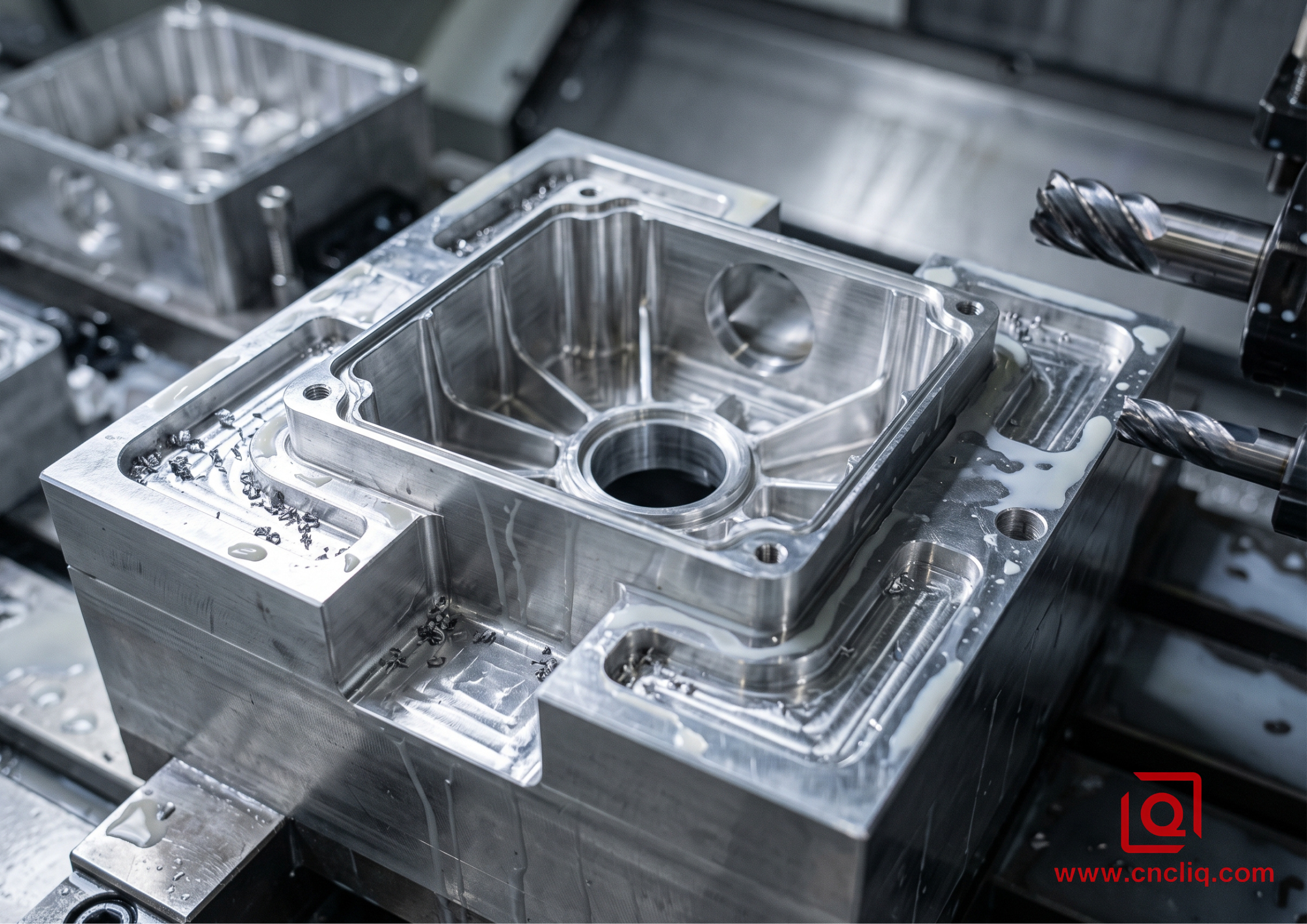
The revised setup delivered flat O-ring surfaces straight off the machine bed without hand scraping.
4. Materials and Machinability Realities
Picking your alloy grade decides whether your CNC operator spends their shift clearing parts or wrestling with chip nests and dull cutting edges.
The workhorse of any precision shop is 6061-T651. It cuts clean, runs easy on tooling, and costs far less than specialty aerospace alloys. Paired with high-rake, polished carbide inserts, it forms neat, tight curls that clear out of deep pockets without packing. Its 276 MPa yield strength handles everyday structural loads, and it takes clear or color-anodized hardcoatings with an even finish.
If your design handles violent shock loads, cyclic fatigue, or tight bearing press-fits, step up to 7075-T651. With yield strengths climbing past 500 MPa, it behaves almost like mild steel on the machine bed, only it cuts like cold butter. The chips break short, snap crisp, and fly away from the cut zone cleanly. The trade-off shows up on your raw stock bill and in corrosion resistance: 7075 costs significantly more per pound and will oxidize if left bare in damp environments, requiring a dependable conversion coat or hardcoat.
Compare both wrought plates to foundry casting alloys like A380. Die casting alloys rely on heavy silicon content—often approaching ten percent—to help liquid metal flow into tight mold cavities. That silicon does not vanish when the metal hardens. It turns into gritty, abrasive micro-particles trapped throughout the part. When you take an end mill to a casting, those silicon particles act like tiny grinding stones, wearing down cutting edges and raising burrs on every exit face. Anodizing a casting is equally messy; the silicon bleeds through, leaving blotchy grey streaks and blisters across sealing faces.
5. Production Economics: Tooling Amortization vs. Cycle Time
Every mechanical project eventually runs into the accounting department. High-volume jobs favor methods that save raw metal, while short runs run away from tooling costs.
Total Cost
  ^
  |               / Hard Tool Die Casting (High NRE, cheap piece-part)
  |              /
  |             /
  |  ..........X (Typical crossover: 800 to 1,500 pieces)
  |           /
  |          /
  |         /  CNC Billet Milling (Zero NRE, flat piece-part cost)
  |        /
  |       /
  +------------------------------------------------------------> Batch Size
Early Prototypes Through 500 Pieces
CNC milling holds an unbeatable edge here. Hardened steel casting dies demand heavy upfront cash and months of toolroom fitting before you see your first good shot. If field testing shows that an internal mounting boss needs to move two millimeters, that hardened steel die often turns into scrap. CNC milling needs only an updated STEP file, modified toolpaths, and a fresh aluminum block. You can change your design on a Wednesday morning and hold finished hardware by Friday afternoon.
Bridge Production (500 to 2,000 Pieces)
This middle run is where design changes decide the path. If your customers are testing the product, shifting sensor locations, or trimming weight, staying on CNC mills protects you from scrap tooling. Modern multi-pallet machining cells run through the dark without human hands around, pulling unit costs down and narrowing the price gap against small-batch castings.
High-Volume Production (5,000+ Pieces)
Once your outside envelope, hole locations, and mounting pads freeze solid, casting methods take over. Yes, you swallow the upfront tooling bill, but cycle times drop from forty minutes of metal-chewing down to twenty seconds on a casting machine. You pay only for the net aluminum in the part, not the bin of chips hauled away under the machine.
6. Five Design Checks Before Releasing Drawings
Before saving your CAD model and sending drawings out for quotes, run through this practical checklist to catch machining problems while they are still cheap to fix:
-
Check Inside Corner Radii: Look straight down into your deepest pockets. Are the inside vertical corners sharp or tiny? Open those radii up. Giving the machinist room to run a thick, rigid end mill cuts machining time drastically and stops cutter squeal.
-
Shorten Thread Depths: Tapping three times the bolt diameter into blind holes does not make the joint three times stronger. In 6061-T6, thread engagement beyond 1.5 to 2.0 times bolt diameter gives you full pullout holding power. Extra hole depth only packs chips, dulls taps, and raises the odds of snapping tools deep inside a finished part.
-
Watch the Pocket Depth Ratio: Keep pocket depths within four times the tool diameter whenever practical. Once tools drop beyond five times diameter, machinists must slow feeds down to a crawl and step the tool down gingerly to avoid snapping shanks.
-
Align Tool Access Angles: Put tapped holes, deep slots, and critical bores onto parallel planes. Even on an advanced 5-axis mill, indexing the workpiece across fewer positional stops saves fixture setup time and keeps cycle times lean.
-
Call Out True Stress Relief: If your part demands tight flatness after hogging out lots of aluminum, mark your drawing for 6061-T651 rather than basic 6061-T6. That single extra designation tells your material supplier to send pre-stretched plate, preventing nasty warping surprises on the inspection bench.
Balancing functional performance against shop-floor cutting mechanics is how solid hardware gets built on time. When your design requires leak-tight density, rigid datum planes, and fast design changes, billet CNC milling earns its place on your bill of materials every single time.
FAQs
Q1: What is the main structural reason to switch from die casting to CNC billet milling?
It usually comes down to hidden voids and leak paths. Die casting locks micro air pockets beneath its chilled surface crust. Cut an O-ring gland or tap a deep hole through that skin, and your pressure boundary fails. Solid rolled plate like 6061-T651 offers pure metallurgical density across the entire core, which cuts out porosity leaks and keeps thread flanks from crumbling under pressure.
Q2: Why does an aluminum part bow or warp right after heavy milling, and how do you stop it?
Raw plate carries trapped tension and compression bands left behind by rolling mills and quench tanks. Rip away 80% of the stock for deep pockets, and that internal balance snaps—banana-peeling the workpiece. The fix is straightforward: spec pre-stretched plate like 6061-T651, hog out the bulk meat first, crack the vise open so the part breathes out residual stress, then run finish passes to hit final size.
Q3: Can a CNC mill produce sharp 90-degree inside corners in deep pockets?
Can’t do it. A spinning end mill leaves its own nose radius on every standing inside wall. If a square mating block has to bottom out flush, you either drop the part onto wire EDM (which tanks throughput and hikes fixture costs), or drop in dogbone or T-bone corner reliefs. That way, an off-the-shelf end mill clears out the corner cleanly with zero tool interference.
Q4: How thin can I design aluminum vertical walls before they chatter or deflect on the mill?
On ribs braced by intersecting webs or outside flanges, 0.8 mm is doable in 6061-T6. For standalone upright fins with zero support, hold at least 1.5 mm, then tack on 0.5 mm of meat for every 10 mm of stand-off height. Skip that extra thickness, and tool pressure simply shoves the wall aside, leaving chatter bands down the face.
Q5: At what production batch size does die casting become cheaper than CNC billet milling?
Tipping points usually land between 800 and 1,500 parts. Below 500 units, coughing up $15,000 to $45,000 for hardened steel tool steel cavities along with an 8 to 12 week wait makes CNC hogging the cheaper route every time. Once prints freeze hard and runs hit thousands, 20-second die-cast shots easily wipe out the initial tooling bill.
Summary
When casting porosity ruins sealing faces or uneven extrusion walls twist off the rack, CNC billet milling provides the structural density and dimensional control that net-shape processes cannot match. By designing around cutter physics—avoiding deep-cavity tool deflection, supporting thin walls, breaking sharp inside corners with relief cuts, and specifying stress-relieved 6061-T651 plate—engineers can bypass expensive, hard-to-modify casting dies and deliver leak-tight, high-stiffness OEM hardware with complete design flexibility from prototype runs through mid-volume bridge production.
Contact Information
Disclaimer
All technical articles, material specifications, machining recommendations, and surface treatment details published on this blog are for informational and reference purposes only. Please note that general blog insights do not replace signed technical agreements. Because custom parts vary by material heat numbers, machine calibrations, and specific tolerances, binding quality specs are governed solely by your approved CAD drawings, signed contracts, and formal quality plans.
All customer case studies featured on this blog have been thoroughly anonymized and sanitized. The performance metrics, manufacturing workflows, and imagery displayed serve solely to demonstrate our custom machining capabilities and do not represent a single universal standard for all orders.
Liqin Manufacturing Team
Built on 18 years of precision engineering experience, Ningbo Liqin Industry manufactures high-tolerance metal components for demanding global markets. We operate out of a 6,500 m² production hub equipped with over 150 machines, running 4-axis and 5-axis CNC machining, mill-turn machining, cold extrusion, and pressure die casting under one roof. This setup allows us to manage projects seamlessly, taking parts from initial CAD concepts directly to finalized shipments.
We handle quality control with zero compromise. We treat tight tolerances with the engineering discipline they require. Backed by ISO 9001, ISO 13485, and IATF 16949 certifications, our QA engineers run strict IPQC, FQC, and OQC checks on every single production batch. From CMM dimensional mapping and optical profiling to hardness and salt-spray testing, we validate your critical specs upfront—so you receive drop-in ready components with zero assembly headaches or costly line stoppages.On top of manufacturing, you can rely on us for two-hour response times on new RFQs, direct support for prototype sampling, and smooth export shipping across Europe, North America, Asia, and Oceania.
Welcome your inquiries and samples. Visit our website or contact us directly for a competitive quote!
