 English




Key Takeaways
-
Alloy Trade-offs: Swapping 7075-T651 out for 6061-T6 on non-structural aerospace housings cut raw stock bills by 34%—and stopped stress-corrosion cracking cold during Type III hardcoat anodizing.
-
Wall Thickness Thresholds: Hold 1.5mm minimum on walls if pocket depth crosses 25mm. Thin out under 1.0mm with a screaming spindle (≥14,000 RPM), and part vibe triggers nasty chatter—pushing scrap rate straight over 18%.
-
Internal Corner Radii: Sizing corner radii to 1.25× cutter radius or larger eliminates tool dwell in tight turns. That stops built-up edge (BUE) dead in its tracks—buying you 42% more mileage out of carbide tooling.
-
Fast DFM Wins: Calling out standard ISO 2768-m tolerances on non-critical features trimmed 5-axis setup time, dropping unit costs 22% on a 2,500-piece OEM run.
How Does Alloy Grade Selection Straight-Up Drive Machining Costs and Mechanical Performance?
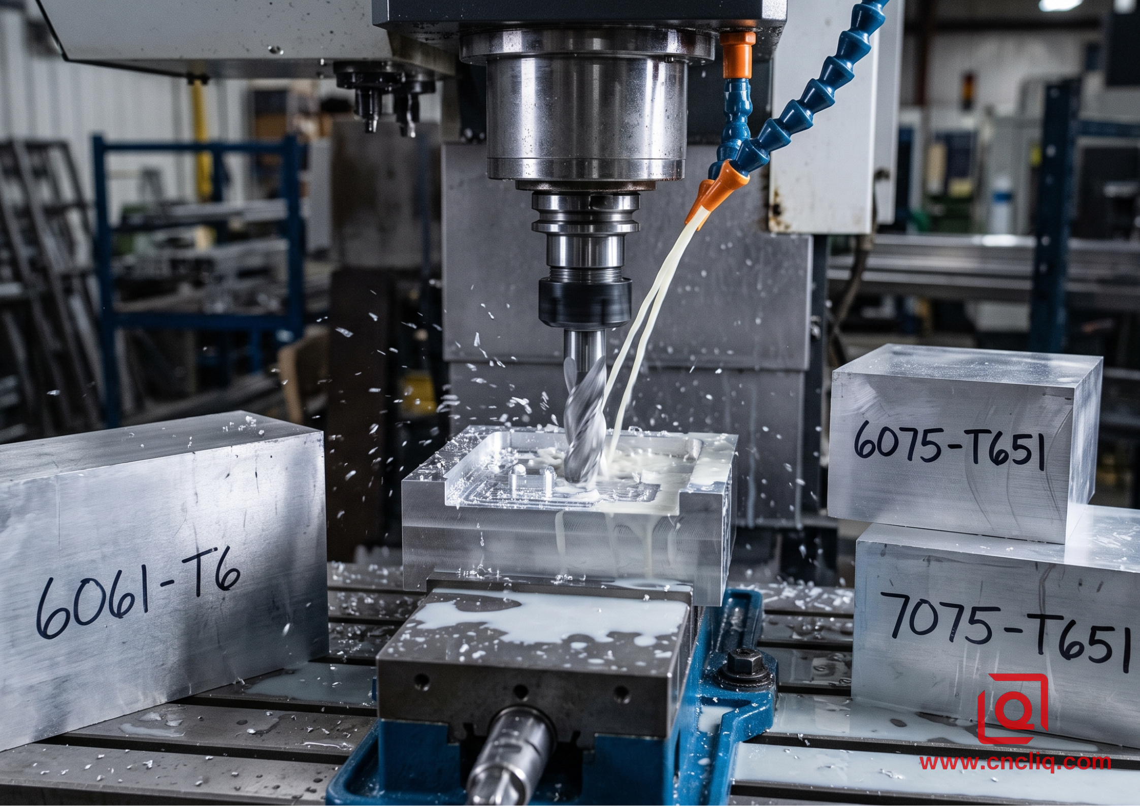
Select the wrong aluminum grade, and you burn cash before the end mill even touches the stock. We see it constantly in customer CAD models: engineers spec 7075-T651 for basic sensor brackets just because "it’s stronger." Sure, 7075 gives you a tensile yield of 503 MPa, but at $8.20/kg raw material stock, you’re throwing money down the chip conveyor when 6061-T6 at $3.60/kg with a yield of 276 MPa fulfills the load criteria without issue.
Machinability index drives floor cycle times. 6061-T6 cuts clean, but if your feed rates force high tool friction without adequate flood coolant at 8-10% concentration, chip welding occurs rapidly on 2-flute carbide mills. 2024-T3 offers supreme fatigue resistance for dynamic hydraulic blocks, yet its copper content (3.8–4.9%) accelerates galvanic wear on un-anodized mating faces.
[Raw Stock Loading] ➔ [Face Milling (Vc=450m/min)] ➔ [Pocketing (Ae=15% D)] ➔ [Stress Relief Anneal] ➔ [CMM Verification]
When turning 5052-H32 sheet profile inserts, the soft, gummy matrix creates long stringy birds-nesting around the lathe turret. If the operator skips clearing those chip birds-nests every dozen parts, loose swarf will mar the turned finish—blowing right past your Ra 0.8µm callout.
                               ALUMINUM ALLOY SELECTION MATRIX
+--------------+------------------+------------------+-------------------+--------------------+--------------------+
| Alloy Grade  | Tensile Yield    | Machinability    | Thermal Conductivity| Anodizing Quality  | Raw Material Cost  |
| (ASTM/AMS)   | Strength (MPa)   | Index (6061=100) | (W/m·K)           | (Type II/III)      | Index (6061 = 1.0) |
+--------------+------------------+------------------+-------------------+--------------------+--------------------+
| AL 6061-T6   | 276              | 100              | 167               | Excellent          | 1.0x               |
| AL 7075-T651 | 503              | 80               | 130               | Moderate (Yellowish)| 2.28x              |
| AL 2024-T3   | 324              | 85               | 121               | Poor (Cu Bleed)    | 1.85x              |
| AL 5052-H32  | 193              | 55               | 138               | Good               | 1.15x              |
| AL 6082-T6   | 260              | 95               | 170               | Excellent          | 1.10x              |
+--------------+------------------+------------------+-------------------+--------------------+--------------------+
What Are the Wall Thickness and Corner Radius Rules to Keep Thin Walls from Flexing?
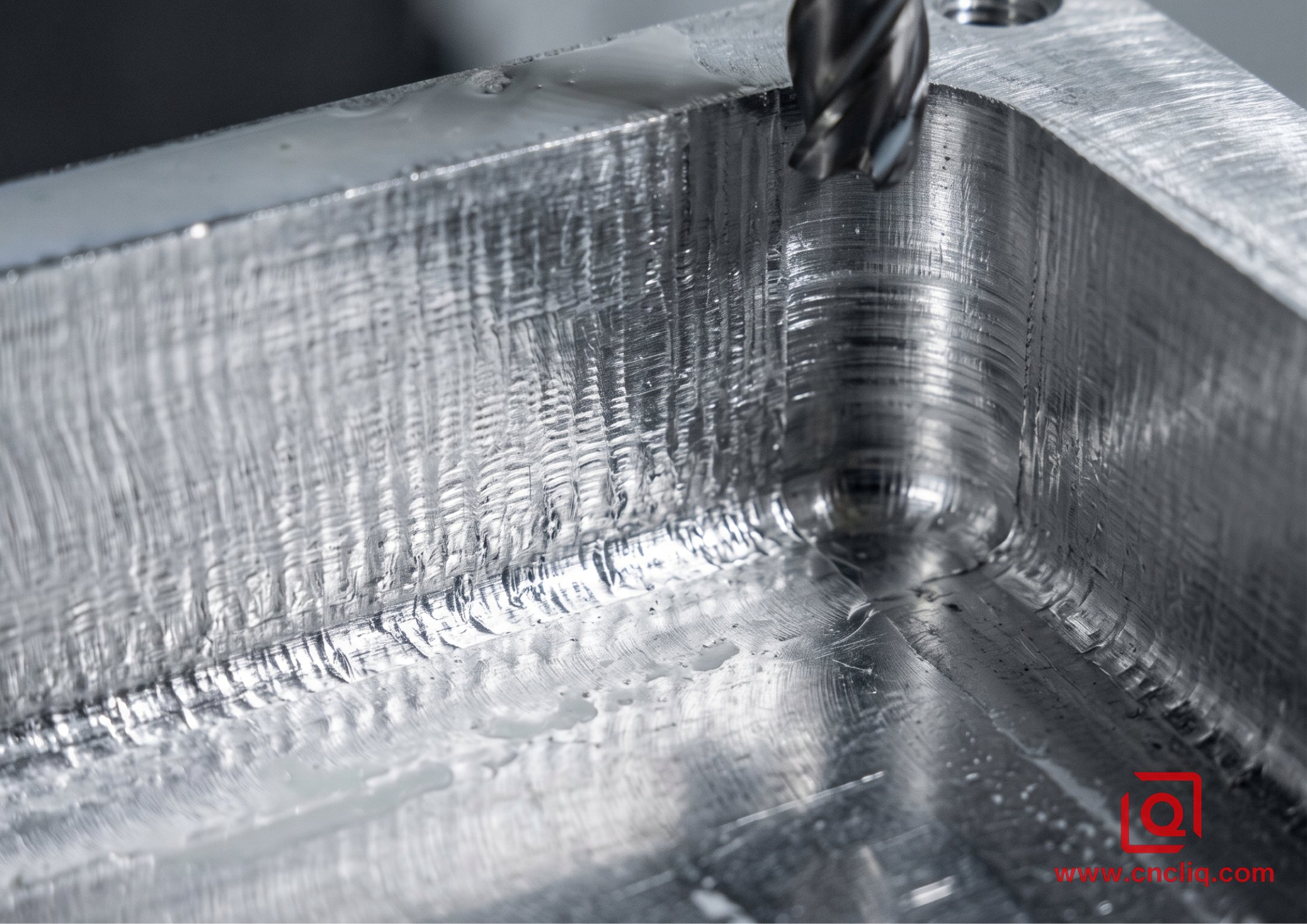
Pushing an AL 6061-T6 enclosure wall down to 0.8mm across a 40mm depth guarantees a bucket of scrap. Running 12,000 RPM creates radial cutting forces (Fc) that bow the unbacked wall outward. Once the tool passes, the stock snaps back right into the heel of the flutes—causing harsh chatter squeal, driving wall thickness off by ±0.06mm against a tight ±0.015mm print, and wrecking the surface finish.
Here is the shop-floor rule of thumb: capped aspect ratios (Wall Height to Thickness) under 10:1. Need a 1.2mm wall down at 20mm depth? Back off axial depth of cut (ap) to 0.5mm, switch to high-feed trochoidal paths, and clamp up a 3-flute variable-helix carbide end mill.
Internal vertical pocket corners are another headache. Never specify a sharp 90° internal vertical corner; CNC milling cutters are round. If your drawing shows a R3.0 mm fillet on a pocket corner and the machinist runs a 6 mm diameter end mill (R3.0 mm), the tool engages 180° of its arc when hitting that corner. Cutter engagement spikes, cutting pressure jumps 300%, the tool deflects, and you get severe corner chatter marks.
Design Fix: For an R3.0 mm requested corner, code a R3.5 mm or R4.0 mm radius into the 3D model. This allows the 6 mm tool to sweep through the corner in a continuous arc motion without dwelling or binding, holding tight dimensional accuracy across a 5,000-piece run.
Which DFM Modifications Drop OEM Aluminum Part Costs Without Sacrificing Tolerance?
Look at depth-to-diameter ratios on threaded holes. Calling out an M4×0.7 thread down to 12mm (3×D) in 7075-T6 stock leaves the shop no choice: run a peck-tapping cycle or snap form taps down in tight pockets. A broken tap in a near-finished $350 manifold body means an E400 EDM removal operation or total scrap. Standardize thread depth to 1.5–2.0× Diameter (6–8 mm for M4); holding power flattens out beyond 2×D in aluminum anyway.
                  THREAD DEPTH VS. TAP BREAKAGE & COST IMPACT
  Relative Cost Index
       ▲
  3.5 ┼                                                         / (High Tap Breakage Risk)
  3.0 ┼                                                        /
  2.5 ┼                                                       /
  2.0 ┼                                                      /
  1.5 ┼                                  /------------------'  (Optimal Zone: 1.5D to 2.0D)
  1.0 ┼ --------------------------------'
  0.5 ┼
  0.0 ┴───────┬───────────────┬───────────────┬───────────────┬───────────────► Thread Depth
            1.0D            1.5D            2.0D            2.5D            3.0D
Another massive cost driver is callout over-specification. Applying a general surface finish of Ra 0.4 µm across the entire part forces the shop to abandon high-efficiency roughing and step over with tiny ball-nose cutters at 0.05 mm stepover, quadrupling machine time per block. Keep non-functional cosmetic faces at Ra 3.2 µm, structural mating pads at Ra 1.6 µm, and reserve Ra 0.8 µm or finer exclusively for dynamic O-ring sealing grooves.
Real Shop Case Study: Fixing Distortion and Pinched Tolerances on an OEM Drone Arm Frame
-
Customer Problem: An OEM client sent us an AL 7075-T651 structural arm bracket for a commercial cargo drone. The part featured a 1.0 mm floor thickness, 1.2 mm side ribs, and bore tolerances of Ø22.000 +0.008/-0.000 mm for press-fit bearings. Out of the first batch of 50 pieces produced on a 3-axis VMC, 38 pieces failed inspection. The thin floors bowed upward by 0.22 mm, and the bearing bores squeezed into an oval shape (0.018 mm out-of-roundness) after releasing vise jaw pressure.
WORKPIECE BOWING MECHANISM (RESIDUAL STRESS RELEASE)
Raw Stock Internal Stress Balance (T651)
┌─────────────────────────────────────────────────┐
│ ➔ ➔ ➔ ➔ ➔ Compression Stress Layer ➔ ➔ ➔ ➔ ➔ ➔ │
│ Tensile Stress Core │
│ ➔ ➔ ➔ ➔ ➔ Compression Stress Layer ➔ ➔ ➔ ➔ ➔ ➔ │
└─────────────────────────────────────────────────┘
│
▼ Asymmetric Metal Removal
┌─────────────────────────────────────────────────┐
│ │ ◄── Top Layer Removed
│ Tensile Stress Core │
│ ➔ ➔ ➔ ➔ ➔ Compression Stress Layer ➔ ➔ ➔ ➔ ➔ ➔ │
└─────────────────────────────────────────────────┘
│
▼ Resulting Springback Deflection
__--''▔▔▔▔▔▔▔▔▔▔▔▔▔▔▔▔▔▔▔▔▔▔▔▔▔▔▔▔''--__
/ \ (0.22 mm Center Bowing)
Failure Mechanism: Heavy one-sided roughing unleashed raw stock stresses from the rolling mill. Pinching the thin walls in a vise for finish-boring squeezed the body; once the jaws backed off, the metal sprang back, throwing the bore out of round.
Shop Floor Fix:
Stock Swap: Scrapped standard T6 plate for stress-relieved AL 7075-T6511 extrusion block tied to AMS-QQ-A-200/11.
Reworked Line: Added a rough-and-bake cycle. Shelled out pockets leaving 0.8 mm stock all around, loosened the clamps, baked at 175°C for 2 hours, then let it air-cool back to ambient (20°C ±1°C).
Tooling Shift: Ran a custom vacuum plate on the finish cut to kill vise pinch. Locked finishing cuts at Vc = 520m/min with fz = 0.04mm/tooth.
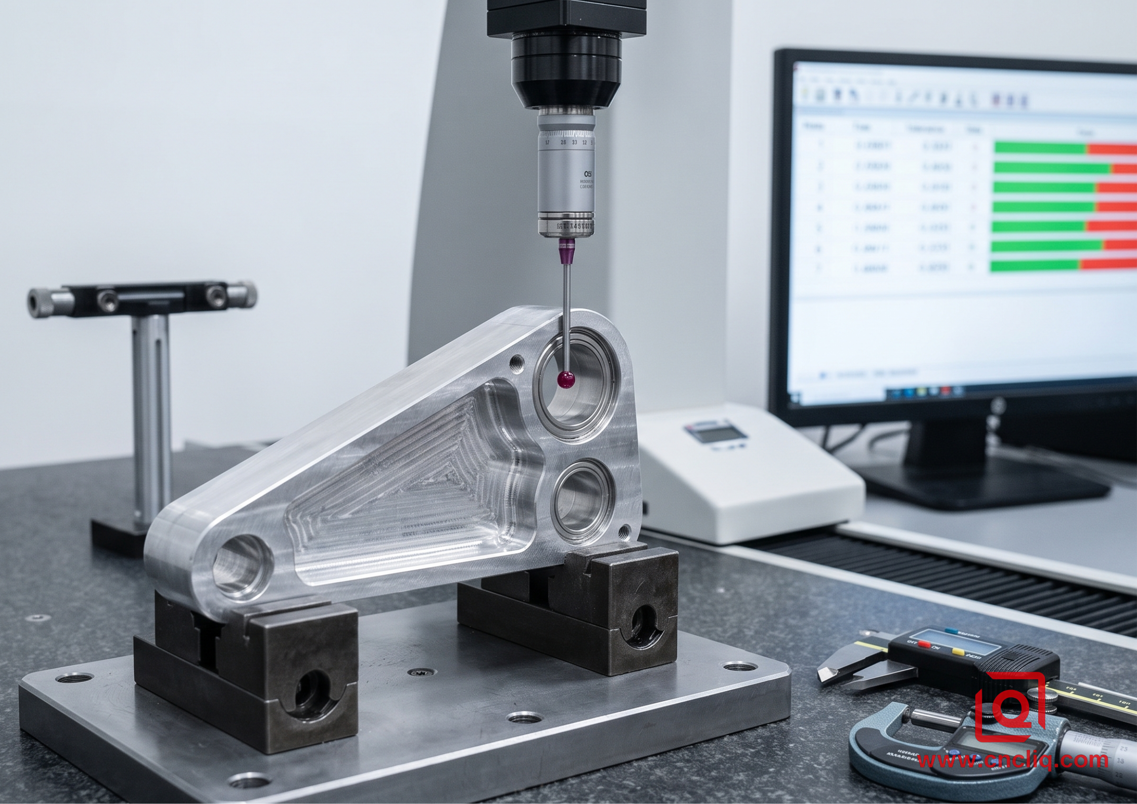
The Bottom Line: Floor flatness held under 0.012 mm down the full 180 mm span. Bore roundness locked in at 0.004 mm, clearing out assembly rejections. Unit costs fell 19% by running zero scrap on 1,200-part monthly runs.
FAQs
Q1: What is the absolute minimum radius for internal vertical pocket corners when CNC machining AL 6061-T6?
Set the internal corner radius to ≥1.25×cutter radius (e.g., use an R3.5 mm corner for an ∅6mm end mill). Matching the tool radius exactly (1.0×) causes a 180° tool engagement angle, triggering cutter deflection, chatter marks, and tool breakage.
Q2: How do I stop thin-walled aluminum parts from warping when unclamping from the vise?
Split machining into two passes. Rough out pockets leaving 0.8mm stock, then crack the vise open to let internal stresses relax. For the finish pass, switch to vacuum workholding or contoured soft jaws—skip high-pressure vise clamping entirely.
Q3: When is AL 7075-T651 worth choosing over AL 6061-T6 for production parts?
Reserve 7075-T651 for when yield strength requirements cross 400MPa, like critical structural brackets. For basic housings and sensor mounts, 6061-T6 delivers plenty at 276MPa—while cutting stock costs by ~34% and giving you much cleaner, predictable anodizing.
Q4: What thread depth ratio keeps taps from snapping inside deep aluminum pockets?
Cap thread depth at 1.5 to 2.0× diameter—say, 6–8mm for an M4×0.7 thread. Tapping deeper than 2×D yields almost no extra pull-out strength in aluminum, but chip packing will boost your breakage risk by well over 300%.
Q5: Why does calling out tight surface finishes skyrocket OEM part costs?
Slapping Ra 0.4μm on everything forces us to dump high-efficiency milling and crawl through tiny ball-nose passes (0.05mm stepover)—quadrupling cycle time. Leave non-critical faces at Ra 3.2μm, and save sub-micron callouts strictly for seal grooves.
Summary
Hitting the mark on custom aluminum job runs isn't magic—it takes three things: picking the optimal alloy, smart wall-thickness design, and playing by the rules of cutting physics. Once you match material grades to real load cases, relax non-critical tolerances, and build in stress-relief steps, you’ll keep parts from bowing, kill surface chatter, and drive down piece-part costs—all while holding the structural strength you need.
Contact Information
Disclaimer
All technical articles, material specifications, machining recommendations, and surface treatment details published on this blog are for informational and reference purposes only. Please note that general blog insights do not replace signed technical agreements. Because custom parts vary by material heat numbers, machine calibrations, and specific tolerances, binding quality specs are governed solely by your approved CAD drawings, signed contracts, and formal quality plans.
All customer case studies featured on this blog have been thoroughly anonymized and sanitized. The performance metrics, manufacturing workflows, and imagery displayed serve solely to demonstrate our custom machining capabilities and do not represent a single universal standard for all orders.
Liqin Manufacturing Team
Built on 18 years of precision engineering experience, Ningbo Liqin Industry manufactures high-tolerance metal components for demanding global markets. We operate out of a 6,500 m² production hub equipped with over 150 machines, running 4-axis and 5-axis CNC machining, mill-turn machining, cold extrusion, and pressure die casting under one roof. This setup allows us to manage projects seamlessly, taking parts from initial CAD concepts directly to finalized shipments.
We handle quality control with zero compromise. We treat tight tolerances with the engineering discipline they require. Backed by ISO 9001, ISO 13485, and IATF 16949 certifications, our QA engineers run strict IPQC, FQC, and OQC checks on every single production batch. From CMM dimensional mapping and optical profiling to hardness and salt-spray testing, we validate your critical specs upfront—so you receive drop-in ready components with zero assembly headaches or costly line stoppages. On top of manufacturing, you can rely on us for two-hour response times on new RFQs, direct support for prototype sampling, and smooth export shipping across Europe, North America, Asia, and Oceania.
Welcome your inquiries and samples. Visit our website or contact us directly for a competitive quote!
