 English




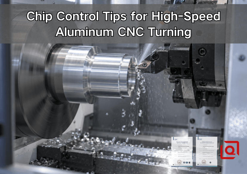
Are you still fighting long aluminum ribbons that wrap around the chuck, drag across a finished diameter, or force an operator to stop an otherwise automatic cycle? Read this guide before lowering the spindle speed or blaming the coolant. In high-speed aluminum CNC turning, the chip is not waste to be ignored. It is a live process signal. Its width, curl, color, direction, and consistency show whether the insert is cutting, rubbing, welding, or losing control.
This article explains a practical way to move from bird-nesting to repeatable chip control. It covers insert geometry, feed per revolution, depth of cut, constant surface speed, coolant direction, boring, grooving, toolpath strategy, inspection, and RFQ information. The aim is not to publish a universal speed-and-feed recipe. No such recipe can account for every alloy temper, bar condition, machine power curve, tool overhang, insert grade, or coolant system. The aim is to help engineers and buyers define a controlled process window that can be proved on the real part.
Quick Answer: What Usually Fixes Long Chips in Aluminum Turning?
Start with a sharp, polished, positive-rake insert made for non-ferrous material. Match its chipbreaker to the actual feed and depth of cut, not simply to the word “aluminum.” Give the chip enough thickness to contact the breaker, aim coolant at the chip-tool interface, keep the holder and workpiece rigid, and verify that the programmed feed is being achieved. If the cut is too light for the selected geometry, the chip may never reach the breaker. If the edge is dull or the feed is timid, aluminum can smear onto the rake face and create built-up edge. If coolant hits the wrong side of the tool, a large flow can still leave the cutting zone dry.
Treat any parameter table as a starting framework. The cutting-tool maker’s application window and the approved first-article trial take priority.
|
Shop-floor symptom |
Likely process cause |
First controlled check |
Avoid |
|
Long ribbon or bird nest |
Feed or depth of cut below chipbreaker range; overly ductile condition |
Confirm insert map, actual feed per revolution, and cutting depth |
Changing speed, feed, coolant, and tool together |
|
Aluminum welded to the edge |
Rubbing, dull edge, poor lubrication, unsuitable surface, or chip recutting |
Stop and inspect the rake face; replace or clean the insert before retesting |
Compensating size with offsets while BUE remains |
|
Scratched finished bore |
Chip flow directed into the bore; weak flushing |
Change tool orientation or coolant aim and protect the finish pass |
Pulling a long chip across a completed sealing surface |
|
Chatter with erratic chips |
Excessive overhang, weak support, unstable engagement |
Shorten the tool assembly and check workholding before tuning speed |
Treating every vibration problem as an RPM problem |
|
Chips break in roughing but not finishing |
Finish allowance is below the chipbreaker’s working range |
Select a finishing geometry or redesign the rough-to-finish allowance |
Forcing a roughing breaker to work on a skim cut |
1. Why “Easy-to-Machine” Aluminum Can Be Hard to Automate
Aluminum removes quickly because many wrought grades cut with relatively low force and conduct heat well. That does not mean they break chips willingly. A ductile alloy can form a continuous ribbon. At high spindle speed, that ribbon reaches the chuck, turret, part catcher, probe, or finished surface quickly. The immediate cost is not only an untidy chip pan. It can be an interrupted cycle, a damaged insert, a false tool-setter reading, a scratched sealing face, or a safety risk during manual removal.
The failure often begins quietly. A small patch of aluminum adheres to the edge. That built-up edge, or BUE, changes the effective rake and nose geometry. Cutting forces move, the finish becomes cloudy or torn, and diameter begins to drift. The operator may add an offset, but the cutting edge is no longer the edge that was qualified. Restoring the tool condition must come before offset correction.
The underlying mechanism is widely recognized. The NIST-hosted reference Machining of Aluminum and Aluminum Alloys notes the long-standing role of carbide in aluminum turning, while Sandvik Coromant’s turning guidance connects light feed with stringers and built-up edge, and excessive feed with poor finish, high power, and chip welding. MSC’s practical review of chip control in aluminum CNC turning adds the production consequence: uncontrolled chips reduce productivity and can become hazardous. These sources agree on the useful lesson—chip control is a system problem, not a single RPM setting.
For alloy selection before process planning, Liqin’s OEM aluminum CNC turning alloy guide provides the material-side context. This article stays narrower: how to make the chosen alloy run reliably at the lathe.
2. Read the Chip Before Editing the Program
The most productive troubleshooting begins with observation. Do not reach into a machine or handle chips while the spindle can move. Observe through the enclosure, stop the cycle safely, and use approved chip-handling tools and plant procedures.
A useful aluminum turning chip is usually separate, compact enough to evacuate, and directed away from the finished surface. It does not need to match a perfect catalog photograph. Chip color is less dramatic than in steel because aluminum carries heat differently, so shape, surface condition, sound, spindle load, and the insert edge are more useful together.
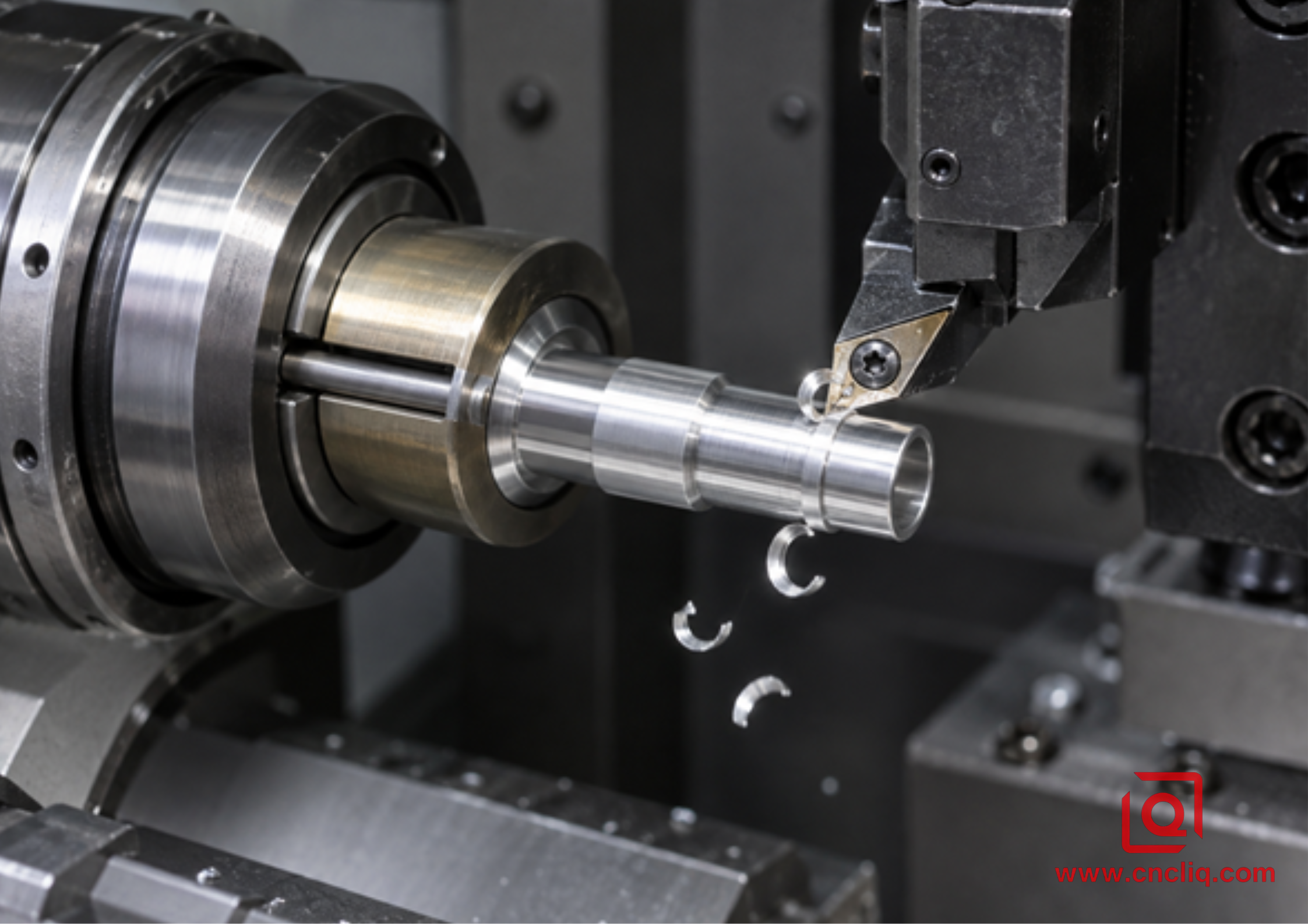
What the common chip forms suggest
· Long, bright ribbon: the edge may be cutting cleanly, but the chip is not contacting or loading the breaker enough. Check feed, depth of cut, breaker geometry, and chip direction.
· Wide spring or bird nest: the chip is curling but not separating. It may hook the part or holder. Review the breaker’s application range and whether the programmed cut actually reaches it.
· Very thin foil-like chip: the tool may be rubbing through a light finish allowance. A sharper finishing geometry can be better than simply adding RPM.
· Gray, smeared, or irregular chip: inspect for BUE, a damaged edge, weak lubrication, or chip recutting.
· Alternating short and long chips: look for feed override, acceleration limits, changing diameter under constant RPM, intermittent engagement, bar runout, or vibration.
Record the observation with the operation number, tool ID, insert corner, alloy and temper, stock lot, feed per revolution, depth of cut, cutting-speed mode, coolant condition, and part count. A photograph of the chip beside a scale is often more useful than a note saying “chips bad.”
3. Match Insert Geometry to the Real Cut
For general aluminum turning, a ground, sharp, positive geometry with a polished rake face is a common first choice because it reduces cutting force and discourages adhesion. That is a starting principle, not a purchase specification. The chipbreaker must also be designed to work at the intended feed and depth of cut.
Roughing and finishing need different answers
A roughing pass has enough chip thickness and cutting depth to drive a more substantial chipbreaker. A finishing pass may be too shallow for that breaker to engage. The result is familiar: roughing drops manageable curls while finishing creates a single ribbon. The fix may be a finishing insert with a breaker positioned closer to the edge, a planned finish allowance that keeps the insert in its working range, or a toolpath change that creates periodic separation without violating the drawing.
Sandvik’s general turning handbook makes the relationship explicit: too small a depth of cut can produce poor chip control and vibration, while too light a feed can produce stringers and BUE. Use that relationship as a diagnostic map. Do not interpret it as permission to increase load beyond the insert, machine, workholding, or part limits.
Edge preparation and coating choice
A heavily honed edge built for interrupted steel cutting can push and smear soft aluminum. Many aluminum applications favor an uncoated, highly polished carbide edge. PCD may be appropriate for stable, high-volume work where finish and tool life justify the tooling cost. Coating selection must be made from the tool supplier’s aluminum-specific recommendation; a coating chosen for hot steel cutting is not automatically suitable for adhesive non-ferrous cutting.
4. Build a Safe Starting Window for Speed, Feed, and Depth of Cut
High-speed turning should be defined by surface speed, not by a memorable RPM. In constant surface speed mode, the control changes spindle speed as diameter changes. The basic relationship is:
Spindle speed, n = (1000 × cutting speed, Vc) / (π × diameter, D)
where n is in rpm when Vc is in m/min and D is in mm. Always set a safe maximum spindle speed. During facing, the theoretical RPM rises sharply as the tool approaches center; the machine limit, chuck rating, workholding, stock balance, and bar-feeding conditions govern the cap.
Feed in turning is normally defined in mm/rev or in/rev. This matters because changing RPM in a feed-per-minute mode also changes chip thickness. When the process intent is a stable chip load per revolution, confirm that the control and program use the intended mode.
|
Variable |
If too low |
If too high |
Validation evidence |
|
Cutting speed |
BUE, dulling, poor surface, low productivity |
Rapid wear, heat, loss of finish |
Edge condition, finish, tool life trend |
|
Feed per revolution |
Thin stringers, rubbing, BUE |
High force, poor finish, chip hammering |
Chip form, spindle load, surface roughness |
|
Depth of cut |
Breaker may not engage; rubbing or vibration |
Power demand, deflection, edge overload |
Chipbreaker map, load, size and form results |
|
Maximum RPM |
Cycle may slow at small diameters |
Workholding or machine limit may be exceeded |
Chuck and machine documentation, proven setup |
Use the exact insert maker’s data to establish the first trial. Then prove 1 variable at a time. A practical sequence is: verify tool and setup, select the maker’s starting cutting speed, set feed and depth inside the breaker map, cap RPM, aim coolant, run a short controlled cut, inspect the chip and edge, measure the part, and document the accepted window.
If the same component also includes milled flats, cross-holes, or backside features, compare the complete setup chain rather than optimizing turning in isolation. Liqin’s guide to CNC turning versus turn-mill machining for concentric aluminum housings explains when keeping those features on 1 machine can protect the functional axis.
5. Put Coolant Where the Chip Is Born
Coolant has 3 jobs in this context: reduce friction at the edge, carry heat, and move the chip away. Volume in the enclosure is not the same as delivery at the cutting zone. A nozzle aimed at the back of the holder may make the window look wet while the rake face remains poorly supplied.
For external turning, aim a stable stream so it reaches the chip-tool interface without being blocked by the chip. For boring, use a holder or bar that delivers coolant close to the edge when possible, because the bore itself traps chips. For grooving and parting, verify that the jet reaches the narrow channel and does not merely flood the outside face.
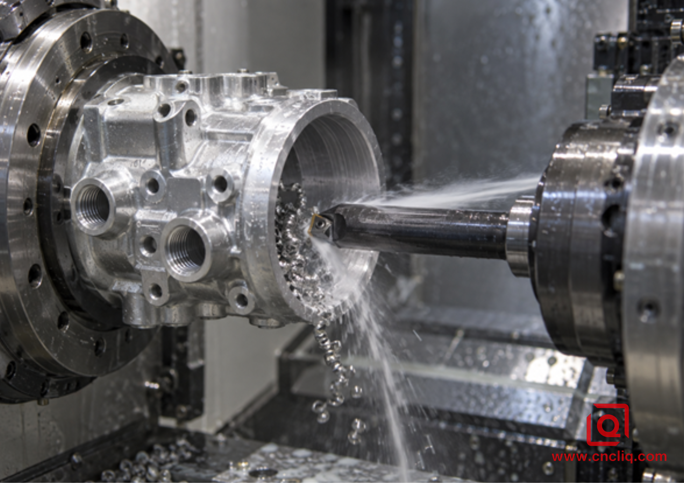
High-pressure coolant can improve chip lifting and evacuation when the machine, holder, seals, enclosure, fluid, and safety controls are designed for it. It is not a universal pressure target. Sandvik describes the hydraulic-wedge effect of precision nozzles between chip and rake face, while Seco’s direct-coolant turning guidance emphasizes precise delivery for cooling and chip removal. Apply the principle, then follow the equipment supplier’s rated limits.
6. Control Chips in Facing, Boring, Grooving, and Threading
Facing toward center
Surface speed falls toward the center if the spindle is capped or constant RPM is used. Feed behavior can also change near center. Expect the last region of the face to behave differently. Use a suitable facing geometry, verify center height, and avoid dwelling at center. If chip control changes at a repeatable diameter, review the actual RPM and feed at that point rather than judging the whole pass by the outer diameter.
Internal boring
The chip has less room and can be dragged across the finished bore. Keep the bar overhang as short as access allows. Choose a positive, narrow geometry that limits cutting force. Direct chips toward the opening and plan the sequence so an aggressive roughing chip does not cross a completed seal diameter. When overhang grows, stability may be the limiting factor before cutting speed.
Grooving and parting
Chip width must fit the groove and evacuate without packing. Use the dedicated insert and holder system, check center height, and supply coolant into the groove. A long string can wrap the part; a chip that is too wide can score both walls. Follow the grooving tool maker’s feed and pecking guidance for the exact width and material.
Threading
Threading creates a constrained chip and repeated engagement. Infeed method changes which flank cuts and where the chip travels. Sandvik’s threading application guidance recommends chip-control geometry and discusses modified-flank infeed for predictable chip direction. Verify the method in simulation and on a first article, especially near shoulders where the chip has nowhere to escape.
7. Programming Tactics When Geometry Alone Is Not Enough
Chip-control cycles and oscillation functions can intentionally interrupt the chip in eligible turning operations. Their availability and correct use depend on the control, machine builder, axis dynamics, and toolpath software. They can be valuable for unattended production, Swiss machining, and internal work, but they are not a substitute for a sharp edge or a stable setup.
Before enabling an oscillating or interrupted-feed strategy:
1. Confirm that the machine and control support the function for the operation.
2. Simulate clearances at the chuck, guide bushing, sub-spindle, shoulder, and toolholder.
3. Check whether the motion will mark a sealing or cosmetic surface.
4. Confirm that the resulting chip can leave the cutting zone.
5. Revalidate size, roundness, surface finish, tool life, and cycle time.
For miniature shafts, support location often decides whether the process is stable. The comparison of Swiss machining and standard CNC turning for miniature aluminum shafts is a useful companion when long length-to-diameter ratios or re-chucking dominate the tolerance chain.
8. A 9-Step Shop-Floor Troubleshooting Routine
1. Make the machine safe. Stop the cycle using the approved procedure. Never pull a chip by hand or open the enclosure during hazardous motion.
2. Preserve evidence. Record tool number, insert corner, operation, part count, alloy, temper, stock lot, overrides, coolant state, and the exact failure location.
3. Inspect the edge. Look for BUE, chipping, wear, contamination under the insert, and seat damage. Restore the known tool condition first.
4. Check the mechanics. Verify insert clamping, center height, holder overhang, boring-bar support, chucking, bar condition, and part rigidity.
5. Confirm program modes. Check constant surface speed or constant RPM, maximum RPM, feed per revolution, and whether acceleration limits reduce actual feed.
6. Compare with the chipbreaker map. Confirm that both feed and depth of cut sit inside the manufacturer’s recommended window for the exact insert.
7. Verify coolant delivery. Observe where the jet lands during the cut and whether the chip blocks it. Check the fluid using the supplier’s maintenance method.
8. Change 1 variable. Run a short, controlled trial and record chip form, load, sound, edge condition, dimensions, and finish.
9. Lock the approved window. Update the setup sheet, tool-life rule, inspection frequency, chip examples, and reaction plan before release.
9. Anonymous Composite Case: 6061-T6 Sensor Housing
An anonymized composite buyer needed a custom 6061-T6 cylindrical sensor housing with a precision bore, external pilot, face-seal groove, radial connector ports, and a cosmetic anodized exterior. The product family is consistent with Liqin’s published custom aluminum machining and inspection capabilities, but the geometry and process narrative below are sanitized and do not reproduce a customer drawing or promise a universal result.
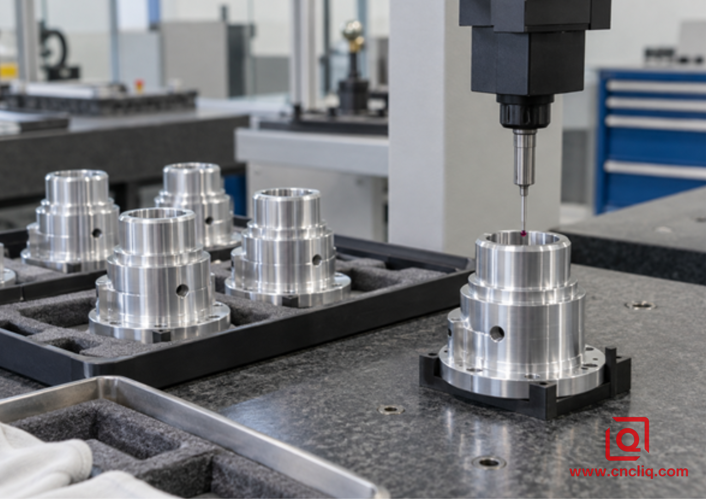
The initial process produced a stable roughing chip but a long finishing ribbon. The ribbon occasionally passed between the boring bar and the completed bore, leaving a visible spiral line. Operators paused the cycle to clear chips, so the quoted automatic cycle was not truly automatic.
The review found 4 interacting issues. The finish allowance was below the roughing insert’s effective chipbreaker range. The boring bar extended farther than required. Coolant hit the outside of the bar instead of the rake face. Finally, the program switched to a very light feed near a shoulder, creating a thin ribbon exactly where escape space was smallest.
The revised route used a dedicated sharp finishing geometry, shortened the bar, repositioned coolant, and kept the finish allowance and feed inside the insert supplier’s published range. The shoulder approach was validated as a separate segment rather than hidden inside one generic finish pass. First-article inspection checked bore size, roundness, face-to-bore relationship, groove geometry, and surface condition. Batch controls then linked insert corner life to measured drift instead of waiting for visible failure.
The commercial result was a process that could be quoted honestly: fewer manual chip-clearing interventions, less risk to the seal bore, and a clearer tool-life and inspection plan. No unsupported savings percentage is claimed because cycle time and scrap reduction depend on the actual drawing, machine, quantity, and approved process.
Liqin’s listed 6061-T6 surge-arrester electrode demonstrates a related combination of aluminum forming, CNC finishing, dimensional inspection, and clean packaging. It is not the same part as this case, but it shows the type of custom cylindrical aluminum component that benefits from planned chip control and downstream surface protection.
10. What Buyers Should Put in an Aluminum Turning RFQ
Reliable chip control begins before a bar reaches the spindle. A supplier cannot plan the insert, workholding, operation order, or inspection route from a screenshot alone. Send:
· Revision-controlled 3D CAD and a legible 2D drawing.
· Aluminum alloy, temper, product form, and any material certification requirement.
· Critical datums, fits, runout, roundness, profile, surface roughness, and sealing surfaces.
· Threads, grooves, burr limits, edge breaks, cleanliness, and cosmetic zones.
· Surface treatment, masked areas, coating allowances, and appearance criteria.
· Prototype and production quantities, annual demand, packaging, and delivery destination.
· Required inspection records, first-article report, capability evidence, or traceability.
· Mating-part and assembly context where it affects functional risk.
For 6061-specific planning, see the 6061 aluminum speeds and feeds guide for a controlled prove-out approach rather than copied numbers. If tight tolerances are the concern after the chip problem is solved, the article on CMM inspection for aluminum OEM machining explains how measurement planning connects drawing intent to production control.
Send Liqin the complete drawing package, quantity, material condition, critical surfaces, and inspection requirements. Our engineering team can review manufacturability, flag chip-control risks, and prepare a process-aware quotation instead of pricing an incomplete assumption.
FAQ
1. Why does 6061 aluminum make long stringy chips during CNC turning?
6061 can deform into a continuous ductile chip, especially when feed or depth of cut is too light to engage the selected chipbreaker. A dull or unsuitable edge, weak coolant delivery, and a very shallow finish pass can make the behavior worse. Confirm the exact insert’s application map, inspect for built-up edge, and test 1 controlled change at a time.
2. Should I reduce spindle speed when aluminum chips will not break?
Not automatically. Lower speed may reduce a heat problem, but it can also encourage built-up edge if the edge starts rubbing or adhering. Chip breaking is strongly influenced by feed per revolution, depth of cut, chipbreaker geometry, and chip direction. Check those variables and the tool maker’s data before changing speed.
3. Is high-pressure coolant always required for high-speed aluminum turning?
No. Precise delivery is more important than quoting a universal pressure. Standard flood coolant can work when it reaches the cutting zone and evacuates chips. Higher-pressure delivery may improve chip lifting in suitable equipment, but every machine, holder, seal, enclosure, and fluid must be rated for the selected pressure.
4. How can chip control be maintained on a very light finish pass?
Use a sharp finishing geometry whose breaker works close to the edge, plan enough finish allowance for that geometry, keep the setup rigid, and prevent the chip from crossing the completed surface. If the drawing permits, a qualified chip-control cycle may help. Validate finish, size, roundness, and tool marks on the real component.
5. What should I send for a reliable custom aluminum CNC turning quote?
Send 3D CAD, a revision-controlled 2D drawing, alloy and temper, quantities, tolerances, GD&T, surface finish, threads, burr and cleanliness requirements, coating, critical cosmetic areas, inspection documents, packaging, and delivery needs. Identifying seal faces and mating features helps the supplier protect the surfaces most vulnerable to chip damage.
Summary
Reliable chip control in high-speed aluminum CNC turning comes from matching a sharp aluminum-specific edge and chipbreaker to the real feed and depth of cut, then supporting that cut with rigid tooling, safe spindle limits, correctly aimed coolant, operation-specific toolpaths, and documented inspection. Read the chip, inspect the edge, change 1 variable at a time, and lock the proven window into the setup plan. For a production-ready quotation, send complete CAD, drawing, material, quantity, surface, and quality requirements so chip control is engineered into the route rather than treated as an operator workaround.
Contact Information
Company: Ningbo Liqin Industry Co., Ltd.Daily customer maintenance & after-sales support:service@shturl. zhuwanying@cncliq.com
New inquiry, quotation & order discussion:business@shturl. zhouli@chinaliqin.com
Hotline: +86 18757148656
Disclaimer
All technical articles, material specifications, machining recommendations, and surface treatment details published on this blog are for informational and reference purposes only. Please note that general blog insights do not replace signed technical agreements. Because custom parts vary by material heat numbers, machine calibrations, and specific tolerances, binding quality specs are governed solely by your approved CAD drawings, signed contracts, and formal quality plans.
All customer case studies featured on this blog have been thoroughly anonymized and sanitized. The performance metrics, manufacturing workflows, and imagery displayed serve solely to demonstrate our custom machining capabilities and do not represent a single universal standard for all orders.
Liqin Manufacturing Team
Built on 18 years of precision engineering experience, Ningbo Liqin Industry manufactures high-tolerance metal components for demanding global markets. We operate out of a 6,500 m² production hub equipped with over 150 machines, running 4-axis and 5-axis CNC machining, mill-turn machining, cold extrusion, and pressure die casting under one roof. This setup allows us to manage projects seamlessly, taking parts from initial CAD concepts directly to finalized shipments.
We handle quality control with zero compromise. We treat tight tolerances with the engineering discipline they require. Backed by ISO 9001, ISO 13485, and IATF 16949 certifications, our QA engineers run strict IPQC, FQC, and OQC checks on every single production batch. From CMM dimensional mapping and optical profiling to hardness and salt-spray testing, we validate your critical specs upfront—so you receive drop-in ready components with zero assembly headaches or costly line stoppages. On top of manufacturing, you can rely on us for two-hour response times on new RFQs, direct support for prototype sampling, and smooth export shipping across Europe, North America, Asia, and Oceania.
Welcome your inquiries and samples. Visit our website or contact us directly for a competitive quote!
