 English




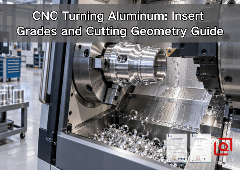
Are you still fighting bird nests, cloudy turned surfaces, or a diameter that drifts after only a few parts—even though aluminum is supposed to be “easy” to machine? The problem is often not the alloy alone. A steel-oriented insert can have the wrong edge preparation, rake face, chip groove, or nose radius for soft, adhesive aluminum. This guide shows how to choose a practical insert grade and cutting geometry, then connect that choice to feeds, chip control, surface finish, and a quote-ready production plan.
Quick answer: For most stable aluminum turning, begin with a sharp, ground, positive-clearance insert in an uncoated fine-grain carbide grade made for ISO N materials. Use a polished rake face, select the nose radius around the actual depth of cut and rigidity, and treat the toolmaker’s cutting-data window as the authority. PCD becomes attractive when long production runs, abrasive high-silicon aluminum, or consistent fine finishes justify the higher edge cost. Everything else depends on the part.
1. Why Aluminum Needs Its Own Insert Strategy
Aluminum usually produces lower cutting forces than steel, but many wrought grades are ductile and adhesive. Under heat and pressure, a thin layer can weld to the rake face and cutting edge. This built-up edge, or BUE, changes the tool’s effective geometry while it is still cutting. The result may be a torn finish, an oversize or undersize diameter, unstable chip flow, or a burr pushed over a shoulder.
A coated, honed insert designed to survive steel is intentionally strong at the edge. In aluminum, that hone can act like a blunt wedge. It raises pressure, encourages rubbing, and gives soft metal a place to stick. A polished aluminum geometry does the opposite: it reduces friction, presents a keen edge, and gives the chip an open path away from the work. Kennametal’s TopSwiss guidance describes polished finishing geometries as a way to improve welding resistance and surface finish, and pairs non-ferrous applications with uncoated fine-grain carbide. Those are useful principles, not a universal part number.
Aluminum is classified in the ISO N application group. That label is a starting point, not a complete grade selection. Two inserts sold for ISO N work can behave differently because their carbide grain size, binder, edge condition, polish, coating, and chip-groove design differ. Always match the supplier’s grade chart to the alloy, operation, stability, coolant strategy, and production target.
If alloy selection is still open, review Liqin’s guide to OEM aluminum CNC turning and alloy behavior. This article starts one level deeper: after an alloy has been chosen, what should touch the metal?
2. Start With the Grade: Uncoated Carbide, DLC, or PCD?
“Grade” describes the cutting material and its engineered wear behavior. “Geometry” describes the shape that makes and controls the chip. A hard grade with the wrong edge can fail, and a perfect geometry on an unsuitable substrate can wear too quickly. Select both.
|
Insert option |
Best starting use |
Main advantage |
Main limitation |
Confirm before release |
|
Uncoated, fine-grain carbide for ISO N |
Prototypes, mixed batches, general 6061/6082/2024/7075 turning |
Very sharp ground edge; economical and versatile |
Edge life may be shorter in abrasive cast aluminum |
Toolmaker’s alloy range, edge polish, minimum chip thickness |
|
Polished PVD/DLC-type non-ferrous grade |
Adhesive alloys, higher speed, jobs where BUE persists |
Low-friction surface can resist aluminum adhesion |
Not every coating is sharp or suitable |
Coating chemistry, edge radius, approved aluminum range |
|
PCD |
Long stable production; abrasive high-silicon cast aluminum; demanding finish consistency |
High wear resistance and long, consistent edge life |
Higher cost; brittle in interrupted cuts |
Interruption, silicon content, cost per accepted part, regrind policy |
|
CBN or ceramic |
Rarely a default for normal aluminum turning |
Specialized use only |
Usually unnecessary for common wrought aluminum |
Written toolmaker recommendation |
For a prototype valve body in 6061-T6, polished uncoated carbide is normally the sensible first trial. It is sharp, available in many shapes, and forgiving when the program is still changing. For a mature order of tens of thousands of stable parts, PCD may lower the cost per accepted component even if one edge costs much more. Calculate the full effect: tool changes, inspection interruptions, scrap risk, cycle time, and whether one edge can complete the critical surface without a stop.
High-silicon cast aluminum is a different wear problem from wrought 6061. Hard silicon particles abrade carbide. This is where PCD often earns attention. Conversely, an interrupted casting skin or cross-hole may punish a brittle diamond edge; a tougher carbide geometry can be safer. “Aluminum” on the drawing is not enough information for a production-tool decision. Seco’s guide to turning grades likewise stresses that insert geometry and grade must be considered together.
3. Decode Insert Geometry Without Getting Lost in the Catalog
The ISO 1832 designation gives a common language for indexable inserts. In a code such as CCGT, the letters describe features including shape, clearance, tolerance class, and insert style. The exact suffixes after the basic code—chipbreaker, grade, edge preparation, handedness, and size—remain supplier-specific. Do not assume that 1 manufacturer’s “AL” geometry is identical to another manufacturer’s aluminum chipbreaker.
|
Insert family |
Angle / access |
Practical aluminum use |
Trade-off |
|
CCGT |
80° diamond; strong corner |
General OD turning, facing, moderate boring, shoulders |
Less profile access than D or V shapes |
|
DCGT |
55° diamond |
Finish contours, smaller diameters, undercuts, light boring |
Weaker corner than C shape |
|
TCGT |
60° triangle; often 3 corners |
General turning and economical medium cuts |
Approach must suit the shoulder |
|
VCGT/VBGT |
35° diamond |
Fine profiling, narrow reliefs, complex contours |
Delicate point |
|
RCGT |
Round edge |
Forming, radii, robust roughing where access permits |
High radial force and chatter risk |
The “G” tolerance class commonly seen in polished aluminum inserts signals a precision-ground insert. The positive-clearance body and ground periphery help create the sharp edge that aluminum wants. Negative double-sided inserts may still remove aluminum under rigid conditions, but they usually demand more cutting force and are not the first choice for a fine, adhesive-alloy finish.

Positive rake and edge sharpness
Positive rake lowers the energy needed to shear the chip and directs it away from the new surface. Many dedicated aluminum geometries use a visibly open, polished rake face and a keen edge. The holder, insert seat, and approach angle contribute to the effective rake; catalog geometry alone does not tell the whole story.
Sharper is not always stronger. A razor-like edge can microchip when it hits a cross-hole, casting inclusion, heavy scale, or unstable interrupted cut. For interruption, move toward a stronger shape, a slightly reinforced edge, a smaller overhang, or a tougher non-ferrous carbide grade—without jumping straight to a heavily honed steel insert.
Chipbreaker: give the chip somewhere to go
The chipbreaker must work inside a feed and depth-of-cut window. If the finishing pass is too shallow to reach the breaker, the chip may remain a long ribbon. If the feed is too low, the edge may rub below its effective minimum chip thickness. If the depth is too high for a light finishing groove, the chip can pack against the shoulder or hammer the edge.
Use the insert maker’s chip-control diagram, then place the actual feed and radial depth of cut inside the recommended zone. Observe the chip. A short, open curl that clears the part is generally healthier than a razor ribbon wrapped around a seal diameter, but chips smashed into tiny fragments can also indicate excessive load.
4. Match Nose Radius to Finish, Feed, and Rigidity
Nose radius influences edge strength, theoretical surface finish, chip direction, and cutting force. Common aluminum finishing radii include 0.2 mm, 0.4 mm, and 0.8 mm, but no radius is automatically “best.”
For an ideal turned surface, a useful geometric estimate is Ra ≈ f² / (32 × rε), where Ra, feed per revolution f, and nose radius rε use consistent units. At f = 0.10 mm/rev and rε = 0.40 mm, the theoretical Ra is about 0.00078 mm, or 0.78 µm. This is only a geometric floor. Runout, vibration, BUE, material inclusions, tool wear, machine condition, coolant delivery, and measurement filtering can all make the real value worse.
A larger radius can support a higher feed for the same theoretical cusp height, but it also increases radial force and contact length. On a thin tube, small bore, or long slender shaft, a 0.8 mm radius may chatter where a 0.4 mm or 0.2 mm radius cuts calmly. Avoid a finishing depth of cut so tiny that the tool only rubs on the honed or rounded edge. Make the pass deliberate and repeatable.
|
Situation |
Practical first direction |
Why |
|
Thin wall or long slender shaft |
0.2–0.4 mm nose radius, positive geometry, light but real chip load |
Reduces radial force and deflection |
|
Stable general OD finish |
0.4 mm radius |
Balanced finish, strength, and access |
|
Rigid roughing or higher feed |
0.8 mm or larger if the breaker supports it |
Stronger corner and better feed capability |
|
Small internal bore |
Small positive insert with minimum overhang |
Controls bar deflection and chatter |
|
Interrupted cut or cross-hole |
Stronger shape/edge; conservative engagement |
Protects the corner from impact |
5. Build a Safe Starting Cut—Then Read the Machine
Begin with the insert manufacturer’s current data for the exact grade, geometry, alloy, and operation. The ranges below are process-planning examples, not guaranteed settings. They help an engineer discuss a trial; they do not replace the supplier chart or a controlled first-off test.
|
Operation |
Insert direction |
Example trial window for rigid wrought aluminum |
Watch |
|
Light finishing |
Polished positive carbide, fine breaker, 0.2–0.4 mm radius |
Vc 250–600 m/min; f 0.05–0.15 mm/rev; ap 0.15–0.80 mm radial |
BUE, chatter, chip wrapping, actual Ra |
|
General turning |
Polished positive carbide, medium aluminum groove, 0.4–0.8 mm radius |
Vc 250–700 m/min; f 0.12–0.30 mm/rev; ap 0.5–3.0 mm radial |
Spindle power, chip evacuation, shoulder packing |
|
PCD finishing |
Supplier-approved PCD geometry |
Often higher speed than carbide; limited by balance, RPM, interruption, and supplier data |
Edge chipping, thermal growth, cost per accepted part |
Use cutting speed, not a favorite RPM, to plan the cut: RPM = (1,000 × Vc) / (π × D). At Vc = 400 m/min and D = 50 mm, the calculated speed is approximately 2,546 RPM. During facing, diameter falls continuously, so constant surface speed raises RPM toward the center. Program a safe spindle-speed cap based on chuck rating, workholding, part balance, and machine limits. Never let the CSS calculation outrun the setup.
Coolant or MQL must reach the cutting edge and move the chip away; spraying the holder is not enough. Aluminum chips are excellent at returning to the cut and scratching the surface the tool just created. On open, safe operations, a properly aimed air blast may evacuate chips effectively, but combustible dust, mist exposure, enclosure rules, and site safety procedures must be considered. Follow the machine, fluid, and workplace safety requirements.
For broader parameter development, use the site’s 6061 feeds, speeds, and tooling guide. For parts combining turned and milled features, the comparison of 3-axis, 5-axis, and mill-turn routes helps decide whether a lathe-only plan will create unnecessary setups.
6. A Shop-Floor Selection Workflow
1. Lock the material condition. Record alloy, temper, stock form, and whether it is wrought or cast. For cast material, record silicon content when available.
2. Define the operation. Separate roughing, finishing, profiling, grooving, threading, and boring. One insert does not need to do everything.
3. Map stability. Note length-to-diameter ratio, wall thickness, tool overhang, interrupted features, chuck engagement, and tailstock or sub-spindle support.
4. Choose cutting material. Start with sharp uncoated fine-grain carbide for general trials; evaluate a low-friction non-ferrous coating or PCD when adhesion, abrasion, or volume provides a business case.
5. Choose shape and clearance. Use C or T for strength and general work, D or V for access, and a positive ground style for low force.
6. Place the cut inside the chipbreaker map. Check both feed and depth of cut. A geometry cannot break a chip outside its working envelope.
7. Select nose radius around rigidity and finish. Do not chase a calculated Ra while ignoring deflection.
8. Run a short controlled trial. Record insert code, lot, Vc, RPM cap, feed, depth, coolant, cycle time, chip form, dimensional trend, and measured finish.
9. Change 1 variable at a time. Inspect the cutting edge before changing speed and feed together. Otherwise, the process teaches you nothing.
This workflow also improves an RFQ. When a buyer sends only a STEP file and “aluminum,” the factory has to price uncertainty. A complete package should include the 2D drawing, alloy and temper, annual volume, lot size, cosmetic zones, required surface finish, critical tolerances, deburring standard, coating, inspection level, and whether dimensions apply before or after finishing.
7. Troubleshooting by Symptom
|
Symptom |
Likely mechanism |
First checks |
Practical correction |
|
Cloudy or torn finish |
BUE, dull/honed edge, rubbing, recut chips |
Inspect rake face; verify actual surface speed |
Fit polished positive insert; restore chip load; improve evacuation |
|
Long bird-nest chips |
Feed/ap outside breaker window |
Plot operating point on supplier chip map |
Move feed or depth into range; change breaker |
|
Chatter on slender OD |
Radius or overhang too large; weak support |
Check tool and part stick-out, jaw contact, center support |
Reduce radius/overhang; add support; lower radial load |
|
Diameter grows during batch |
BUE, wear, thermal drift, insert movement |
Trend dimensions; inspect seat and edge |
Clean seat; stabilize temperature; improve grade and offset plan |
|
Burr at shoulder |
Dull edge, poor approach, pushed material |
Check edge, tool height, path, remaining stock |
Use sharper geometry; revise finish path |
|
PCD edge chips |
Interruption, vibration, impact |
Review cross-holes, stock variation, runout |
Use tougher carbide or supported PCD; improve stability |
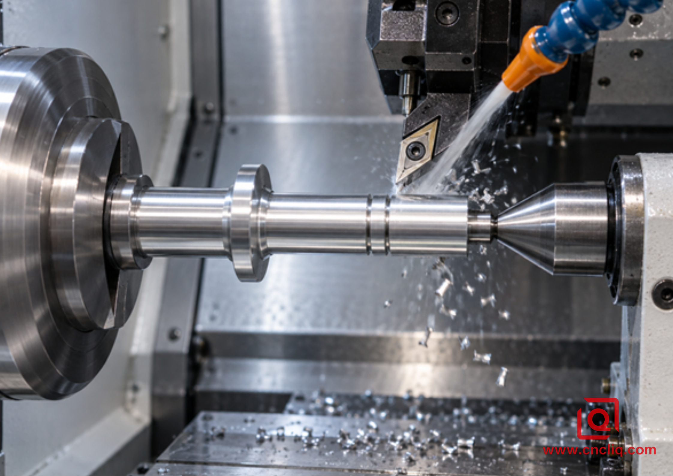
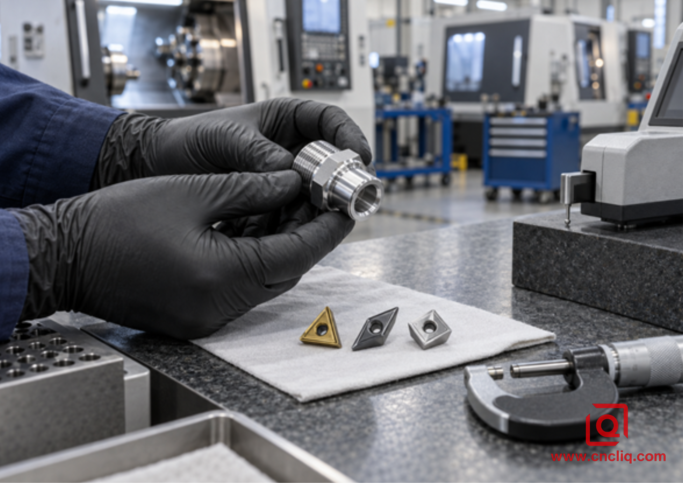
Do not diagnose finish by appearance alone. Measure surface roughness across the specified direction, check diameter at a controlled part temperature, and inspect the edge with magnification. A shiny part can still fail Ra; a visible feed pattern may still be dimensionally stable and acceptable.
8. Anonymized Composite Case: Aluminum Pneumatic Valve Sleeve
The following is an anonymized composite example created to show a realistic process-development method. It is not presented as a record from 1 identifiable customer or as a universal performance guarantee.
An industrial-automation buyer requested a 6061-T6 pneumatic valve sleeve with a 32 mm finished OD, a precision internal spool bore, 2 external O-ring lands, and black anodizing. The annual forecast was 18,000 pieces in monthly releases. The most important requirements were a 0.015 mm total bore-size window before coating, Ra 0.8 µm on the dynamic sealing lands, controlled edge breaks, and no loose chips in the internal passages.
The first process concept used a general-purpose coated insert left in the turret from a steel job. The edge produced a bright surface for several parts, but aluminum gradually adhered to the rake face. Finish became cloudy, chip ribbons crossed the sealing land, and offset corrections increased. Rather than compensating around an unstable edge, the process team rebuilt the operation around chip formation.
For rough turning, the team selected a precision-ground positive C-shape insert in an uncoated non-ferrous carbide grade, with an open aluminum chip groove and 0.8 mm nose radius. For the finish lands, it used a polished D-shape insert with a 0.4 mm radius, providing access beside the shoulder with lower radial force. Feed and radial depth were placed inside the toolmaker’s published chip-control region. Coolant nozzles were aimed at the rake face and chip exit, not the holder body. The bore was finished with the shortest practical positive boring tool, and the critical surfaces were measured only after a defined temperature-stabilization period.
The control plan treated anodizing as part of manufacturing, not decoration. The drawing review separated pre-coat dimensions from final functional requirements, identified masking zones, and required a first-article report linking bore, land diameter, roughness, and coating condition. A short capability run was approved before the monthly batch.
The commercial lesson is as important as the technical one: a low insert price did not produce a low part cost. Stable chip control reduced operator intervention and protected sealing surfaces. A buyer comparing suppliers should ask how the proposed insert strategy, coating allowance, cleaning route, and inspection plan work together—not merely ask for the fastest spindle speed.
Liqin’s published precision aluminum manifold product example shows the kind of cross-bored, cleaned, inspected aluminum component where chip control and sealing-surface discipline matter. The site’s application-field product collection provides further verified examples of custom aluminum work for industrial and communication equipment.
9. What to Send for a Useful CNC Turning Quote
A high-quality quotation needs enough information to select both the process and the risk controls. Send:
· 3D CAD plus a controlled 2D drawing;
· full alloy, temper, and acceptable stock form;
· critical dimensions, datum scheme, geometric tolerances, and surface-roughness callouts;
· prototype quantity, release quantity, annual volume, and target schedule;
· anodizing or plating specification, color expectations, masking, and whether dimensions apply before or after treatment;
· mating-part or functional notes for bores, threads, O-ring lands, and press fits;
· inspection documentation, material certification, cleanliness, packaging, and traceability requirements.
If you are unsure whether polished carbide or PCD is economical, include the forecast and critical-surface length. Liqin’s engineering team can review the drawing, identify insert-access or chip-control risks, and return a manufacturing proposal. Use the site’s CNC machining RFQ checklist and contact the team with CAD files and the required delivery window.
FAQs
1. What is the best insert grade for CNC turning 6061 aluminum?
For most prototype and general-production 6061 work, a precision-ground, mirror-polished, uncoated fine-grain carbide grade intended for ISO N materials is the strongest first choice because it combines a keen edge with reasonable cost. A dedicated low-friction non-ferrous coating may help when adhesion remains a problem, while PCD becomes easier to justify on long, stable runs or surfaces that must remain consistent for many parts. The toolmaker’s grade chart and a controlled trial should make the final decision.
2. Are CCGT or DCGT inserts better for aluminum?
Neither is universally better. CCGT offers a stronger 80° corner and works well for general OD turning, facing, and many boring operations. DCGT has a slimmer 55° point, so it reaches profiles, undercuts, and shoulder details more easily and can reduce contact on delicate finish cuts. Choose CCGT when strength and general use dominate; choose DCGT when access and light profiling dominate, then confirm the holder angle and toolpath provide clearance.
3. Should aluminum turning inserts be coated or uncoated?
Uncoated polished carbide is often preferred because grinding and polishing can preserve a very sharp, low-friction edge. Some coatings made specifically for non-ferrous work, including certain DLC-type solutions, can resist adhesion without sacrificing the required sharpness. A general steel coating is not automatically suitable and may have an edge hone that promotes BUE. Select by the manufacturer’s aluminum application data, not by coating color.
4. Why do aluminum chips remain long even with an aluminum chipbreaker?
A chipbreaker only works within its designed feed and depth-of-cut range. A very light finishing pass may never push the chip into the groove, while a low feed can create a thin ribbon that bends instead of breaking. Check the exact insert’s chip-control map, increase feed or depth within safe limits, improve coolant direction, and verify that the alloy itself is not especially ductile. Never change parameters without considering finish, rigidity, and spindle load.
5. When does PCD pay for itself in aluminum turning?
PCD is most attractive when the cut is stable, production volume is high, tool-change downtime matters, finish consistency is valuable, or abrasive silicon rapidly wears carbide. It may not pay on prototypes, frequently revised parts, or interrupted cuts that chip a brittle diamond edge. Compare cost per accepted part, including insert cost, edges used, cycle time, inspection stops, scrap, and tool changes; the cheapest edge and the cheapest finished component are often different.
Summary
Successful CNC turning of aluminum starts with a sharp ISO N-oriented cutting edge, but the complete decision joins grade, polish, shape, rake, chipbreaker, nose radius, feed, depth of cut, rigidity, and coolant delivery. Begin with polished positive carbide for general trials, evaluate PCD when abrasion or volume supports it, keep the cut inside the supplier’s chip-control window, and validate the process on the actual alloy and setup. A quote that includes alloy temper, critical finishes, coating requirements, batch volume, and inspection needs lets the factory build a stable process instead of pricing unknowns.
Contact Information
Company: Ningbo Liqin Industry Co., Ltd.
Daily customer maintenance & after-sales support:service@shturl. zhuwanying@cncliq.com
New inquiry, quotation & order discussion:business@shturl. zhouli@chinaliqin.com
Hotline: +86 18757148656
Disclaimer
All technical articles, material specifications, machining recommendations, and surface treatment details published on this blog are for informational and reference purposes only. Please note that general blog insights do not replace signed technical agreements. Because custom parts vary by material heat numbers, machine calibrations, and specific tolerances, binding quality specs are governed solely by your approved CAD drawings, signed contracts, and formal quality plans.
All customer case studies featured on this blog have been thoroughly anonymized and sanitized. The performance metrics, manufacturing workflows, and imagery displayed serve solely to demonstrate our custom machining capabilities and do not represent a single universal standard for all orders.
Liqin Manufacturing Team
Built on 18 years of precision engineering experience, Ningbo Liqin Industry manufactures high-tolerance metal components for demanding global markets. We operate out of a 6,500 m² production hub equipped with over 150 machines, running 4-axis and 5-axis CNC machining, mill-turn machining, cold extrusion, and pressure die casting under one roof. This setup allows us to manage projects seamlessly, taking parts from initial CAD concepts directly to finalized shipments.
We handle quality control with zero compromise. We treat tight tolerances with the engineering discipline they require. Backed by ISO 9001, ISO 13485, and IATF 16949 certifications, our QA engineers run strict IPQC, FQC, and OQC checks on every single production batch. From CMM dimensional mapping and optical profiling to hardness and salt-spray testing, we validate your critical specs upfront—so you receive drop-in ready components with zero assembly headaches or costly line stoppages. On top of manufacturing, you can rely on us for two-hour response times on new RFQs, direct support for prototype sampling, and smooth export shipping across Europe, North America, Asia, and Oceania.
Welcome your inquiries and samples. Visit our website or contact us directly for a competitive quote!
