 English





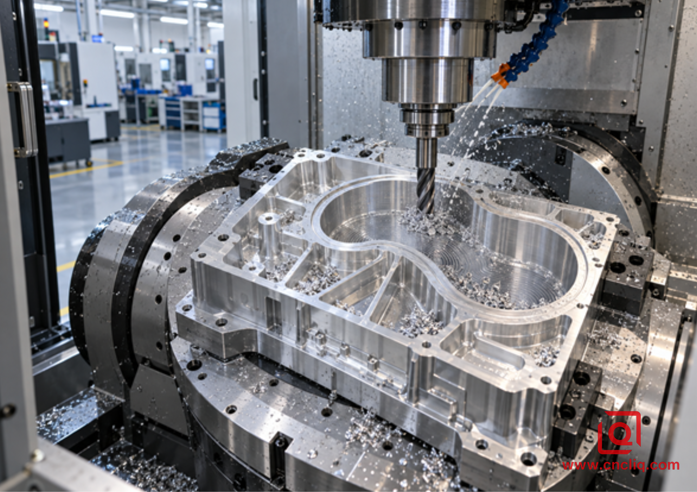
Are you still fighting broken end mills, welded chips, and unpredictable wall finish every time an aluminum pocket gets deeper? The first few parts may sound fine. Then spindle load starts climbing, chips remain at the bottom, and one tight corner turns a steady cut into a sudden overload. By the time the operator reacts, aluminum has packed a flute or the cutter has snapped below the holder.
Trochoidal milling can make deep-pocket aluminum work far more predictable, but a looping toolpath is not a cure by itself. Tool diameter, flute geometry, stickout, entry motion, corner engagement, coolant direction, and machine acceleration must work together. This guide explains the method from a shop-floor viewpoint so design engineers, buyers, and production teams can decide when to use it, how to set up a safe trial, and what to include in an RFQ.
Quick Answer: When Does Trochoidal Milling Help?
Trochoidal milling advances the cutter through overlapping arcs while keeping radial engagement relatively low and consistent. The tool can use more flute length axially, so wear is spread along the edge instead of being concentrated at the tip. The method is most useful when tool load, reach, corners, or chip evacuation limit the process.
|
Shop-floor condition |
Why a conventional path struggles |
What a tuned trochoidal path changes |
|
Deep pocket with restricted chip exit |
Chips fall under the cutter and are cut again |
Short engagements give directed air or coolant more chances to remove chips |
|
Tight internal corner |
Engagement and spindle load rise sharply |
CAM limits engagement and uses smooth linking arcs |
|
Long tool stickout |
Radial force bends the tool and excites chatter |
Low radial width reduces side load when the tool-holder assembly is rigid |
|
Thin pocket wall |
Heavy radial pressure pushes the wall away |
More consistent engagement reduces roughing deflection |
|
Expensive billet or unattended cycle |
One packed flute can scrap a high-value part |
Stable load and proven chip control make wear easier to monitor |
The method is not automatically faster in a shallow, open cavity. A conventional offset path may be simpler there. Trochoidal milling earns its keep when it turns an unstable deep cut into a controlled one.
1. What Happens at the Cutting Edge?
A conventional pocketing path can move from light side cutting into a corner where the cutter suddenly sees much more material. Chip thickness rises, radial force climbs, and the tool deflects. In aluminum, a hot chip may smear onto the edge and create built-up edge. The rounded edge then rubs instead of shearing, which generates more heat and accelerates failure.
A trochoidal path tries to keep maximum engagement within a planned range. The cutter rolls into the material, reaches controlled engagement, and rolls out before the next loop. This intermittent contact helps chips leave and gives the cutting edge time outside the workpiece.
Low radial engagement also causes radial chip thinning. The maximum chip thickness becomes smaller than the programmed feed per tooth might suggest. Copying a conventional feed into a low-engagement path can therefore make the edge rub. CAM may compensate, but the programmer should still verify effective chip thickness against the tool maker's data. A quiet cut is not always a healthy cut.
For definitions of cutting speed, feed per tooth, axial depth (ap), and radial engagement (ae), see Liqin's 6061 aluminum speeds and feeds guide. If alloy selection is still open, the comparison of 6061, 7075, and 5052 for CNC milling explains why identical toolpaths can behave differently.
2. Why Deep Aluminum Pockets Destroy Tools
Deep cavities combine several failure mechanisms. Fixing only one tends to move the problem elsewhere.
Chip recutting and built-up edge
Aluminum chips are light, ductile, and likely to collect at the pocket floor. A recut chip can wedge between the flute and wall, scratch a finished surface, raise torque, or weld onto the edge. Good chip shape is not enough; the chips must leave the cavity.
Tool deflection from stickout
Deep reach requires a longer assembly, while stiffness falls rapidly as overhang increases. Use the shortest holder and reach that clear the geometry, keep the tool core strong, and consider 3+2 or 5-axis positioning if tilting the part permits a shorter cutter. Liqin's guide to multi-axis milling of complex aluminum geometries covers that access-versus-rigidity decision.
Corner engagement
If an internal radius nearly matches the cutter radius, the corner can surround the tool with material. A smaller rougher, larger design radius, or rest-roughing sequence is usually safer than forcing one tool to clear every corner.
Trapped heat and moving walls
Tall walls can block coolant from the actual cutting zone. Meanwhile, removing a large percentage of a billet releases residual stress and reduces part stiffness. Stress-relieved plate, balanced stock removal, controlled clamping, and separate finishing allowances remain essential even with an excellent toolpath.
3. Is Your Pocket a Good Candidate?
Review pocket depth, minimum radius, wall height and thickness, floor thickness, holder clearance, entry space, and chip exit direction before programming.
Good candidates include deep open pockets, narrow slots that can be opened with a cutter smaller than the slot, long trimming paths, and cavities with corners that would otherwise create load spikes. The strategy can also help rough near thin walls because radial force is lower and more consistent.
Poor candidates include cavities with no room for looping motion, entrances that trap both chips and coolant, and machines that cannot execute short arcs smoothly. Trochoidal motion also loses value if thousands of tiny line segments make the control hesitate. CAM smoothing, arc fitting, look-ahead capacity, and a realistic path tolerance can matter as much as the programmed feed.
Design changes often deliver the cheapest improvement. Increase nonfunctional internal radii, provide a clear entry region, avoid unnecessarily deep cosmetic cavities, and identify which walls and floors are truly critical. Those choices reduce tool reach, risk, and quotation uncertainty.
4. Choose the Cutter and Holder as One System
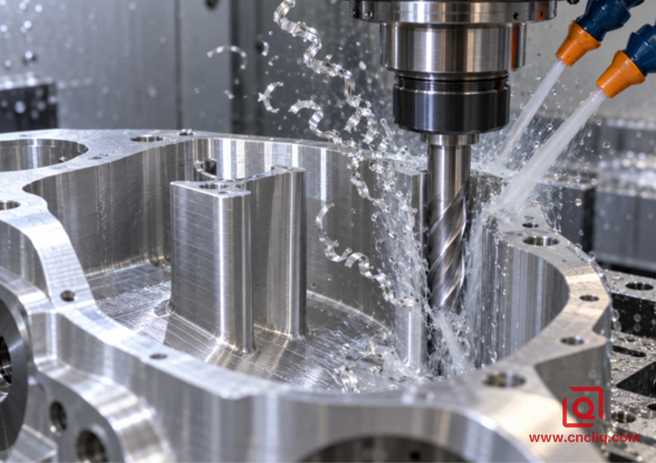
For deep-pocket aluminum roughing, a sharp solid-carbide end mill with 2 or 3 flutes is a practical starting point. Two flutes provide generous chip space. Three flutes can add core stiffness and feed capacity while retaining more chip space than a general-purpose 4-flute tool.
Look for polished flutes, a sharp positive geometry intended for non-ferrous material, and enough flute length for the planned axial cut. Bare polished carbide, zirconium-nitride options, and diamond-like carbon coatings are common choices, depending on alloy, coolant, and tool-supplier guidance. A coating that works well in steel should not be assumed suitable for aluminum.
Keep gauge length short, clean the taper and collet, and measure runout near the cutting edge. Runout gives one flute more work than the others, erasing the benefit of controlled engagement.
A Sandvik Coromant application guide describes trochoidal milling as an established process in aluminum and publishes reference starting values: cutter diameter near 65% of slot width, programmed stepover around 8% of cutter diameter, axial depth around 1 to 1.5 times diameter, and maximum radial cut below 20% of cutter diameter. An Iscar milling applications guide likewise notes that gradual wear across the full cutting edge can increase tool life in deep slots, pockets, and cavities. These are credible reference points, not universal recipes.
5. Build a Safe Starting Window
|
Variable |
Planning reference |
Reasons to reduce it |
|
Radial engagement, ae |
Published guidance commonly falls near 5% to 15% of diameter; 8% is a useful trial reference |
Long stickout, weak fixture, thin wall, poor chip exit, high runout |
|
Axial engagement, ap |
Use a meaningful part of the flute; 1.0D to 1.5D appears in published guidance |
Limited flute length, holder clearance, wall movement, low rigidity |
|
Cutter diameter |
Small enough to preserve chip space and avoid corner burial |
Tight radius, restricted entry, limited evacuation |
|
Entry |
Smooth helical or tangent entry; avoid straight plunge unless the tool is designed for it |
Thin floor, center-cutting limit, unstable long tool |
|
Feed |
Calculate from verified rpm, flute count, and chip load, then check chip thinning |
Chatter, rising load, poor acceleration, uneven wear |
|
Finish stock |
Leave consistent radial and axial allowance for a separate finish |
Thin walls, distortion, critical sealing surfaces |
Start with the exact cutter supplier's data. Calculate spindle speed as n = (1000 × Vc) / (pi × D), where Vc is cutting speed in m/min and D is diameter in mm. Calculate table feed as Vf = n × z × fz, where z is flute count and fz is feed per tooth in mm/tooth.
Then watch the real machine. Small loops may be acceleration-limited, so actual feed can remain well below the command. A stable path shows a narrow spindle-load band. A repeated spike at one location points to excess engagement, an abrupt link, or a chip dead zone. A gradual rise across several parts suggests wear, runout, coolant condition, or built-up edge.
For 2024 work, Liqin's guide to machining 2024 aluminum and managing tool wear reinforces the need to evaluate speed, chip load, ae, and ap together rather than treating rpm as the master setting.
6. Chip Evacuation Is Part of the Toolpath
Through-tool coolant is valuable when the cutter and holder support it because the stream reaches below the rim. Correctly aimed external nozzles can also work in open pockets. Air blast may be effective in approved dry or minimum-quantity processes. Whatever the method, confirm that flow reaches the deepest cut.
Do not point every nozzle from one side. One stream should reach the active engagement; another can help lift chips toward an opening. Control coolant concentration and cleanliness with the fluid supplier's range and the shop's measurement procedure rather than applying one universal percentage to every product.
Before committing an expensive billet, cut a representative depth, stop safely, and inspect the cavity. A chip pile in one corner reveals more than a smooth CAM animation. For unattended machining, validate evacuation at the deepest and most enclosed region, not only during the first visible level.
7. CAM Details That Protect Tool Life
1. Use a tangent or helical entry. A straight plunge restricts chip space and loads the tool center unless the cutter is designed for it.
2. Limit engagement through corners and narrow regions. Do not let rest material surprise the tool with nearly full-width contact.
3. Keep links smooth. Abrupt direction changes create jerk and can slow the machine below the intended feed.
4. Stay down only when chip conditions permit. Avoid wasting time on needless retracts, but do not link through a chip pile.
5. Separate roughing from finishing. Leave uniform stock for the final wall, floor, sealing land, or bore operation.
6. Use rest machining. A smaller tool can clean corners without burying the main rougher.
7. Simulate the holder and neck, not only the cutting edge.
8. Review the posted program. Excessive point density may cause control hesitation or data starvation.
8. Protect Thin Walls and Verify the Result
Low engagement does not remove residual stress or make a flexible wall rigid. Rough while surrounding material still supports the feature. Leave balanced stock, allow relaxation when the route needs it, and finish in controlled passes.
For tall walls, alternate sides or use axial bands so force is not always directed toward the weak side. For thin floors, avoid trapping hot chips below the tool and minimize unnecessary axial force. Fixturing should support functional datums without squeezing the part into temporary conformance.
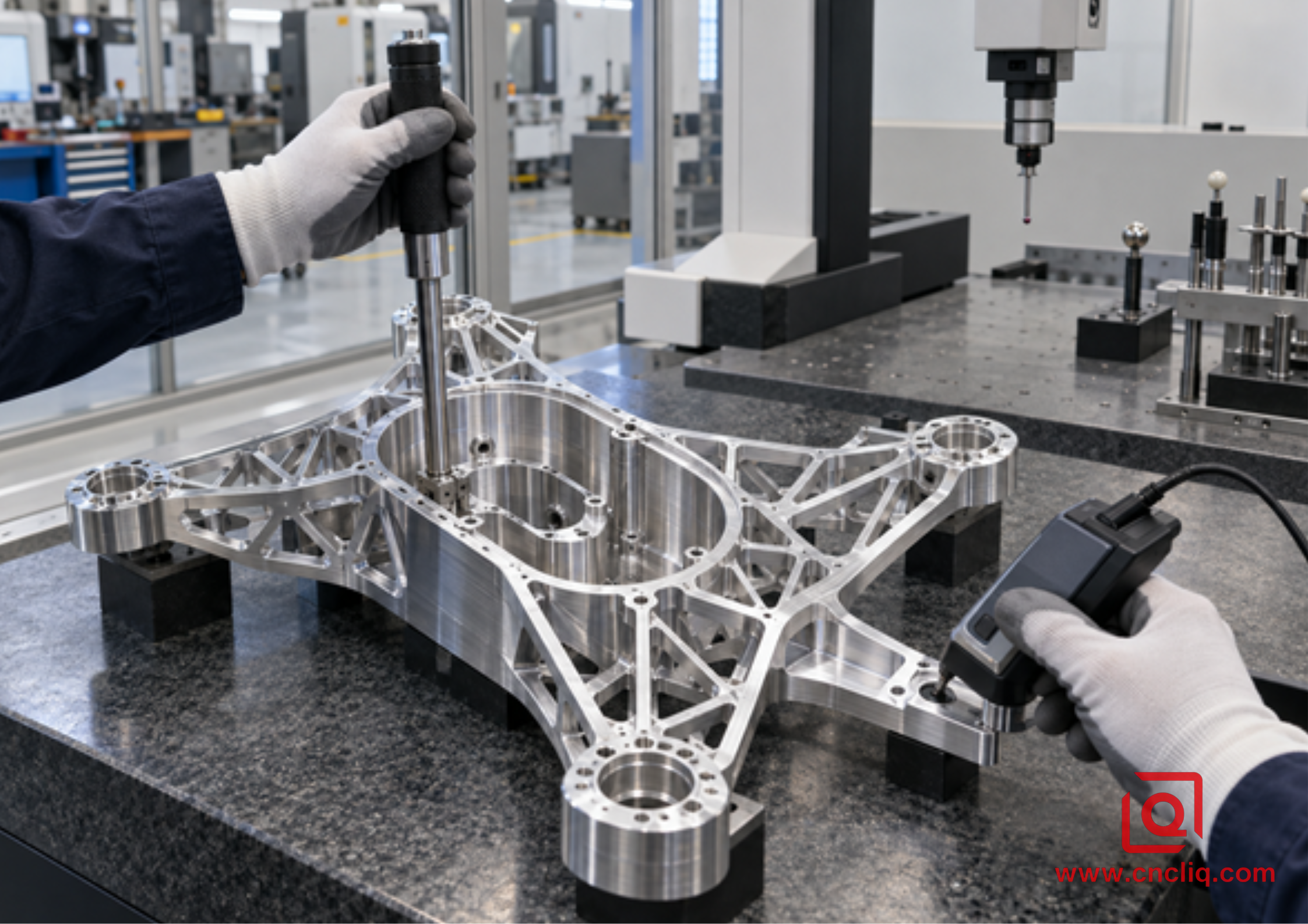
Inspection should follow function. A CMM can map pocket position, wall profile, and datums; a bore gauge may suit a functional diameter; a surface profilometer verifies specified texture. Measure after the part stabilizes at a controlled, recorded temperature. Agree on the datum setup and inspection method before production when the part contains sealing lands, deep bores, or intersecting passages.
9. Anonymous Composite Case: Deep-Pocket Vacuum Manifold

This anonymized composite case is based on common custom-machining conditions. It illustrates a credible engineering workflow, not a claim that one parameter set applies to every order.
An industrial automation customer required a 6061-T651 vacuum-manifold body with a deep teardrop cavity, intersecting port bosses, a raised sealing land, and cross-drilled passages. The cavity needed extended reach, while the surrounding sealing face had to remain stable. The plan covered prototypes followed by repeat batches after functional approval.
The initial concept used a general-purpose end mill and a conventional offset path. It was easy to program, but the cutter spent too much time at high engagement. Chips gathered near the narrow end, causing repeated load peaks and uneven edge condition.
During DFM review, the customer allowed a larger nonfunctional internal radius and identified floor regions that were clearance-only. The programmer could then use an aluminum-specific 3-flute rougher with a shorter assembly. Low radial engagement, useful axial engagement within the tool maker's limits, smooth helical entry, and controlled corner motion formed the new roughing strategy. One coolant nozzle targeted the cut; a second pushed chips toward the opening.
The team left uniform stock on the walls and sealing land. After unclamping and stabilization, the datum was re-established and critical surfaces were finished separately. Indexed machining completed the cross ports. CMM inspection covered datums and port position, while the sealing surface received dedicated flatness and texture checks.
The main gain was predictable production rather than a headline feed rate. Spindle load became steadier, the narrow end stopped collecting chips, and tool changes could be planned from observed wear instead of emergency breakage.
Liqin's published precision aluminum manifold block is a relevant product example for buyers evaluating machined passages, sealing faces, anodizing, and inspection. The custom aluminum machining category shows additional material and product options.
10. Troubleshooting by Symptom
|
Symptom |
Check first |
Correction path |
|
Aluminum welded to flute |
Chip load, lubrication, edge condition, recutting |
Restore verified chip load, improve delivery, clear chips, use aluminum geometry |
|
Chatter only at full depth |
Stickout, holder contact, weak wall, worn tool |
Shorten assembly, verify clearance, reduce ae, stage finishing |
|
Load spike in each corner |
Engagement, radius, remaining stock |
Adjust CAM, use a rest tool, increase allowable design radius |
|
Scratched pocket floor |
Chips below cutter, stay-down links |
Redirect coolant or air and add safe chip-clear moves |
|
One flute wears faster |
Runout and holder cleanliness |
Clean, reassemble, measure near the edge, replace worn collet |
|
Programmed feed is high but cycle is slow |
Acceleration limits or dense code |
Smooth path, review loop size, post, and control look-ahead |
|
Part moves after unclamping |
Clamp distortion or residual stress |
Reduce clamp force, balance roughing, add relaxation and re-probing |
11. What to Send for a Fast, Accurate RFQ
Send a stable 3D model and controlled 2D drawing, then identify alloy and temper, prototype and batch quantities, critical-to-quality dimensions, datums, pocket depth, minimum radii, thin-wall zones, finish requirements, certificates, inspection reports, and any pressure or leak test. Include mating-part information when a sealing land, bore, or port relationship drives function.
Cost is governed less by pocket volume than by reach, wall stiffness, corner radius, tolerance, inspection, setup count, and tool access. Do not tighten every dimension by default. Mark the features that control sealing, alignment, bearing fit, optical position, or assembly. That allows the supplier to protect function without adding unnecessary machining time.
For confidential projects, request an NDA before transferring controlled files and state any retention or access requirements in the RFQ. For a useful schedule, separate prototype approval from production lead time and identify required finishing and inspection documents.
Liqin supports prototype and production custom CNC machining. Send your model, drawing, quantity, alloy, and CTQ list for an engineering review and quotation.
FAQ
1. Is trochoidal milling the same as adaptive clearing?
The terms overlap but are not always identical. Trochoidal milling traditionally uses repeated looping arcs, while adaptive or dynamic clearing is a broader CAM strategy that varies motion to maintain a target engagement. Both aim to reduce load variation. For an RFQ, focus on controlled engagement, entry, chip evacuation, and verified machine motion rather than a software brand name.
2. What radial engagement should I use for deep-pocket aluminum milling?
Published starting guidance often places trochoidal engagement around 5% to 15% of tool diameter, with 8% a useful reference and maximum radial cut kept below 20% in the cited Sandvik guide. The correct value depends on the exact cutter, flute length, stickout, runout, alloy, machine rigidity, coolant, and wall stiffness. Begin with tool-maker data and validate through load, chip form, sound, temperature, and edge inspection.
3. How much does a custom deep-pocket aluminum part cost?
There is no responsible unit price without geometry, quantity, alloy, tolerances, finish, and inspection scope. Deep reach, small corner radii, thin walls, multiple setups, anodizing, and full CMM reporting add cost; larger radii, clear tool access, realistic tolerances, and repeat batch quantities can reduce it. Submit a STEP file, controlled drawing, annual volume, and CTQ list for a comparable quotation.
4. What lead time should I expect, and how is drawing confidentiality handled?
Lead time depends on material availability, tooling, fixture complexity, prototype approval, finishing, and inspection documentation, so it should be confirmed in the formal quote rather than taken from a generic blog estimate. If the design is confidential, request an NDA before file transfer, identify export-control or access restrictions, and agree on how drawings, revisions, and inspection records will be stored and shared.
5. What quality records should I request for a deep-cavity part?
Ask for records that match function: material certification when required, first-article or dimensional inspection for critical features, CMM results for datum relationships, surface-texture evidence for sealing lands, and pressure or leak-test results when passages carry fluid. Avoid demanding a large report package by habit; define CTQs, acceptance criteria, sampling, and document format on the purchase order or quality plan.
Summary
Trochoidal milling can extend tool life in deep aluminum pockets when the entire process is controlled: keep radial engagement low and consistent, use flute length responsibly, correct for chip thinning, minimize runout and stickout, direct chips out of the deepest zone, protect thin walls with balanced stock and separate finishing, and verify the result through load, tool wear, and dimensional inspection. A complete RFQ should state alloy and temper, geometry, quantity, CTQs, finish, confidentiality needs, and inspection scope so the manufacturing route addresses real assembly risk rather than guessing.
Contact Information
Company: Ningbo Liqin Industry Co., Ltd.
Daily customer maintenance & after-sales support:service@shturl. zhuwanying@cncliq.com
New inquiry, quotation & order discussion:business@shturl. zhouli@chinaliqin.com
Hotline: +86 18757148656
Disclaimer
All technical articles, material specifications, machining recommendations, and surface treatment details published on this blog are for informational and reference purposes only. Please note that general blog insights do not replace signed technical agreements. Because custom parts vary by material heat numbers, machine calibrations, and specific tolerances, binding quality specs are governed solely by your approved CAD drawings, signed contracts, and formal quality plans.
All customer case studies featured on this blog have been thoroughly anonymized and sanitized. The performance metrics, manufacturing workflows, and imagery displayed serve solely to demonstrate our custom machining capabilities and do not represent a single universal standard for all orders.
Liqin Manufacturing Team
Built on 18 years of precision engineering experience, Ningbo Liqin Industry manufactures high-tolerance metal components for demanding global markets. We operate out of a 6,500 m² production hub equipped with over 150 machines, running 4-axis and 5-axis CNC machining, mill-turn machining, cold extrusion, and pressure die casting under one roof. This setup allows us to manage projects seamlessly, taking parts from initial CAD concepts directly to finalized shipments.
We handle quality control with zero compromise. We treat tight tolerances with the engineering discipline they require. Backed by ISO 9001, ISO 13485, and IATF 16949 certifications, our QA engineers run strict IPQC, FQC, and OQC checks on every single production batch. From CMM dimensional mapping and optical profiling to hardness and salt-spray testing, we validate your critical specs upfront—so you receive drop-in ready components with zero assembly headaches or costly line stoppages. On top of manufacturing, you can rely on us for two-hour response times on new RFQs, direct support for prototype sampling, and smooth export shipping across Europe, North America, Asia, and Oceania.
Welcome your inquiries and samples. Visit our website or contact us directly for a competitive quote!
