 English





Are you still trying to cure a noisy 6061 pocket by changing RPM, feed, and coolant all at once? Or are you comparing CNC quotations and wondering why one supplier promises an aggressive cycle while another asks about stock condition, wall thickness, and inspection datums? Read this guide before the next trial. It explains how a shop-floor engineer builds a high-speed machining window for a 6061 aluminum block, how to recognize when the numbers are only impressive on a CAM screen, and what information helps a buyer receive a reliable quotation instead of a risky guess.
The short answer is simple: there is no universal “best” HSM setting for 6061. A responsible starting point is tied to the exact cutter, machine, holder, overhang, toolpath, radial engagement, pocket depth, coolant delivery, fixture, and material temper. I would rather see a modest-looking setup run 100 clean parts than watch a record-setting cut survive once. The number worth keeping is the one that still works in the last corner, on a partly hollow block, with an edge that has already done some cutting.
1. What HSM Changes When the Workpiece Is a Block
Call it high-speed machining and everyone looks at the RPM box. The more revealing screen is usually the toolpath. Watch the cutter enter an inside corner: does the engagement grow smoothly, or does it suddenly bite into a wedge of stock? Dynamic, adaptive, and constant-engagement routines approach this in slightly different ways, yet the shop-floor aim is familiar—use a relatively narrow radial cut, make sensible use of the flute length, and avoid surprise loads. High RPM helps only after that groundwork is sound.
A 6061 block also changes while material is removed. A deep pocket reduces stiffness. A thin floor becomes easier to push. Residual stress in plate or extruded stock may reveal itself as the section becomes unbalanced. Clamping force that was harmless on a solid blank can distort the nearly finished part. That is why block machining requires a sequence, not a single speed-and-feed answer.
This article deliberately complements, rather than repeats, Liqin's existing guides. Use the 6061 aluminum speeds and feeds guide for the basic formulas and diameter examples, and the aluminum HSM and maximum MRR article for a broader material-removal discussion. Here, the focus is how those ideas are applied to a prismatic block from stock review through first-article release.
2. Lock the Inputs Before Calculating Anything
An HSM setup begins at the drawing and stock certificate. “6061 aluminum” is incomplete. Confirm the temper and stock form specified by the customer. A plate, bar, extrusion, forging, or near-net blank can behave differently as material is removed. Do not substitute T6, T651, or another condition without drawing approval and documented material control.
Next, mark the drawing by behavior, not just by feature name. An open pocket can shed chips; a narrow slot cannot. A short outer wall may stay quiet while a 60 mm-deep cavity rings near the bottom. Circle the thin floors, sealing lands, bearing bores, ports, cosmetic faces, and dimensions tied to GD&T datums. Some areas can be roughed for output. Others need support left in place until late in the route.
The setup sheet should tell the next operator what was actually proven. Write down the alloy condition and stock form. Record the cutter's real catalog number, because “12 mm carbide” says almost nothing about the flute shape or edge. Add the machine's usable speed range, holder, measured runout, and tool projection. Then capture axial depth, radial engagement, CAM operation, and how air or coolant reaches the pocket.
Do the same for workholding. Where does the blank sit? In what order are the clamps tightened? Which inspection features are checked before finishing stock disappears? Keep the fixture drawing, cutter data, preset record, and ballooned drawing with the job. Until those details exist, an attractive RPM/feed pair is still a supervised experiment—not a released production setting.
3. Calculate a Defensible Baseline
Start with 3 ordinary milling equations. Sandvik Coromant publishes the metric forms, and they are easy to audit on a calculator:
n = (vc × 1000) ÷ (π × D) for spindle speed, vf = fz × n × zc for table feed, and Q = (ap × ae × vf) ÷ 1000 for material removal rate.
The symbols are less intimidating than they look. Cutting speed vc is in m/min; D is the effective cutter diameter in mm. Feed per tooth is fz, spindle speed is n, and zc is the number of cutting edges doing work. Axial depth and radial engagement are ap and ae. The final Q value is cm³/min.
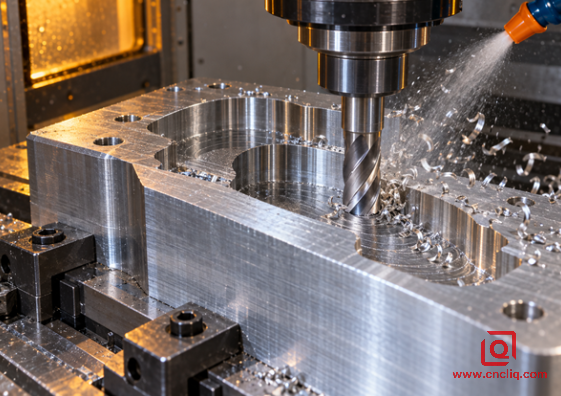
Now put numbers on the bench. Take a 12 mm, 3-flute aluminum end mill. Imagine that the data sheet permits 300 m/min and 0.07 mm/tooth at the engagement being considered. RPM calculates to 7,958. Feed calculates to 1,671 mm/min. With 18 mm axial depth and 1.2 mm radial engagement, nominal MRR is 36.09 cm³/min.
That result is a worksheet answer. I would still check the effective diameter, corner radius, approved flute length, balance limit, holder, runout, stickout, spindle power, and the way chips escape. I would also watch whether the control ever maintains 1,671 mm/min in the actual geometry. Seco's guidance is useful here: cutting data must be interpreted for the application and its objective. In other words, the exact cutter sheet comes first; the machine and setup decide what survives the trial.
{width=594 height=420}
4. Use the Machine's Real Envelope, Not Its Brochure Maximum
Small tools expose a common mistake. The calculation asks for more speed than the spindle has, so somebody types the machine maximum and leaves the old feed in place. Chip load has now changed, whether anyone meant it to or not. Use the safe RPM the spindle, holder, and tool can share; then work the feed equation again. The same discipline applies in reverse when RPM is raised. Otherwise a cutter that looks fast may only be rubbing faster.
Commanded feed is not always achieved feed. Acceleration, jerk control, block-processing speed, smoothing settings, tiny line segments, and inside radii can slow the axes while spindle speed remains constant. The result is a low chip load exactly where engagement may be rising. A parameter sheet should therefore include the programmed feed, the toolpath style, the minimum internal radius, and any corner-feed rule.
Maximum RPM is only one corner of the machine envelope. Look at power and torque where the cut will run, then check holder balance, pullout risk, and the permitted speed of every rotating component. A weak link can sit anywhere between the spindle taper and the cutting edge. The fixture, program, and coolant system belong in that chain as well.
5. Match the Tool to the Operation
For many 6061 block operations, a sharp carbide end mill designed for aluminum is a sensible starting family. Polished flutes and generous chip space help the chip leave. Two flutes provide more space and are often useful in full slots, small diameters, or restricted evacuation. Three flutes can increase productivity in open profiling and constant-engagement roughing when the machine and chip path are capable. More flutes can work in a controlled, shallow-radial strategy, but flute count alone is never proof of a faster process.
The comparison in 2-flute versus 3-flute carbide end mills for aluminum is useful when selecting the geometry. The key purchasing question is not “Which flute count is best?” It is “Which exact tool clears the chip created by this engagement, pocket depth, coolant method, and spindle?” Use the shortest assembly that reaches the present cut—not every cut in the model. One long tool often saves a change on paper and gives the time back through chatter, cautious feed, or a poor wall. A stout rougher, a rest tool, and a local detail tool can be the quicker combination. On multi-sided blocks, compare 3-axis versus 5-axis machining by access, effective reach, setup count, and datum continuity. The badge on the machine door is not the decision.
Avoid blanket claims about coatings. Some aluminum operations favor an uncoated, highly polished edge; particular toolmakers also offer low-friction coatings designed for nonferrous materials. Use the recommendation for the exact catalog tool. A coating that performs well in steel is not automatically suitable for aluminum.
6. Program Engagement Before Chasing Speed
The roughing path should avoid sudden burial in corners. Use a controlled entry such as a helical or ramp move when the tool supports it. Keep radial engagement consistent through inside radii, link moves, and rest areas. If the cutter meets a leftover island or a narrow channel at close to full width, the original feed may no longer be appropriate.
Radial chip thinning also needs deliberate treatment. At small radial engagement, the actual chip can be thinner than the nominal feed-per-tooth value suggests. CAM or toolmaker guidance may apply a compensation, but compensation is not an invitation to multiply feed without checking arc of contact, runout, cutter geometry, and machine acceleration. The target is a controlled chip of the intended thickness, not the largest feed number.
Look at the finish stock in simulation before looking at the cycle time. A wall carrying 0.25 mm next to a corner carrying 1.00 mm will not ask the finish tool the same question. Make the allowance predictable where the geometry permits. Decide in advance which operation establishes the datums, when bores and sealing faces are finished, and where inspection interrupts the route.
7. Make Chip Evacuation Part of the Parameter Set
Bright aluminum chips are useful only when they leave the cutting zone. Chips recut in a pocket can score the floor, damage the edge, raise load, and create built-up edge. Directed air, mist, or flood coolant can be appropriate depending on the machine, operation, local safety rules, and tool guidance. A stream that looks strong at the door may never reach the bottom of a deep cavity.
Aim delivery at the cutting edge and the chip exit route. Watch where chips accumulate after a toolpath change. Verify fluid concentration and condition when a water-miscible system is used, following the supplier's instructions and shop safety program. Do not publish a universal pressure or concentration when the site's verified process documents do not support it.
The cut usually gives a warning before it fails. This is the short troubleshooting sheet we would want beside the machine:
|
Symptom |
Likely checks |
Controlled response |
|
Aluminum sticks to a flute |
Is the edge still sharp? Is feed falling while RPM stays high? Are chips circling the pocket? |
Stop the cycle. Clean or replace the edge, clear the pocket, and verify the actual feed/RPM pair. |
|
A deep wall begins to sing |
Check projection, runout, wall support, and whether engagement grows near the bottom. |
Shorten the assembly or change the local path/support; do not merely turn every setting down. |
|
Straight cuts look fine but corners do not |
The axes may be slowing just as the tool takes a wider bite. |
Review the corner move and the achieved feed, then program a local rule. |
|
Fresh floor has random scratches |
Loose chips may be passing under the tool; dirt may also be trapped at a fixture contact. |
Redirect the flush or air and clean at the planned stage. |
|
Size moves after the clamps open |
Suspect clamp distortion, released stock stress, an unbalanced pocket, or a hot inspection. |
Check the free-state part and revisit clamp order, roughing balance, rest time, and inspection condition. |
|
Load jumps only in leftover corners |
Rest stock is probably changing the arc of contact. |
Give that stock its own rest-machining move, tool, and feed. |
8. Protect Thin Walls, Floors, and Released Surfaces
At OP10, the blank feels almost indestructible. Two deep pockets later, it may behave like a tray. That change catches people because the program has not changed—only the part has. Where geometry permits, alternate the heavy removal, leave ribs or surrounding stock to support delicate features, and delay the thinnest walls. The finish pass on a flexible wall deserves its own engagement, not a copy of the rigid outside profile.
Clamping deserves the same attention as speed. Confirm datum contact, jaw or fixture location, support height, and tightening sequence. Excessive force may flatten the blank during machining and allow it to spring after release. Too little force can allow movement. The correct method must be proven on the actual fixture and documented.
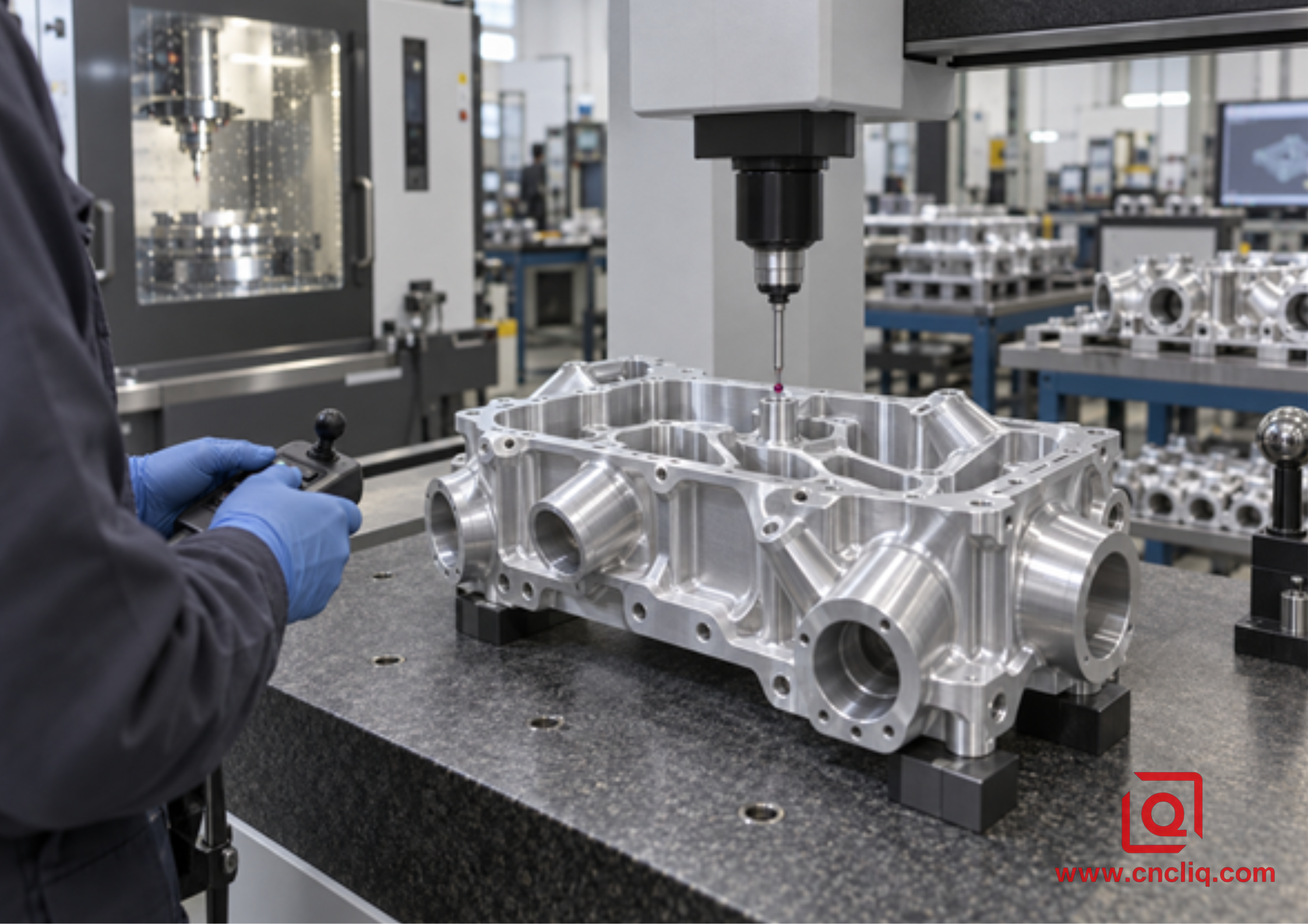
Temperature affects both the part and the measurement. A component measured immediately after a warm cut may not match the same component after stabilization. ISO 1 defines 20°C as the standard reference temperature for dimensional product specification and verification, but that does not mean every part instantly reaches 20°C when it leaves the machine. Define the inspection condition and allow the process plan to reach it.
{width=594 height=420}
9. Validate the Window One Change at a Time
Start under supervision. Confirm tool assembly, work offset, clearance, coolant or air direction, stock allowance, and correct program revision. Run the planned trial below the intended production aggressiveness if the setup is unproven. Observe sound, chip form, chip evacuation, spindle load trend, tool condition, surface, burrs, and the temperature of the part and fixture. Stop for an abnormal change; do not wait for the tool to fail.
Change one primary variable at a time. If RPM, feed, engagement, coolant direction, and tool overhang all change together, the next result teaches very little. Record the approved combination, including tool life criteria and the point at which the edge is indexed or replaced. A stable window has a center, not only a maximum. Production should run with room for normal variation in material lot, tool wear, coolant condition, and ambient temperature.
A useful release sequence is:
1. Verify drawing revision, material condition, and stock orientation.
2. Verify tool identity, holder, overhang, runout, and maximum RPM.
3. Simulate the path and review minimum radii, rest stock, and engagement peaks.
4. Confirm fixture contact, clamp sequence, and tool clearance.
5. Run a supervised first cut and document observations.
6. Inspect critical rough-stage allowances before the finish operation.
7. Stabilize the part as required by the control plan.
8. Complete first-article inspection against the ballooned drawing.
9. Freeze the proven program, setup sheet, inspection plan, and reaction limits.
10. Anonymized Illustrative Case: Long Electronics Cold Plate
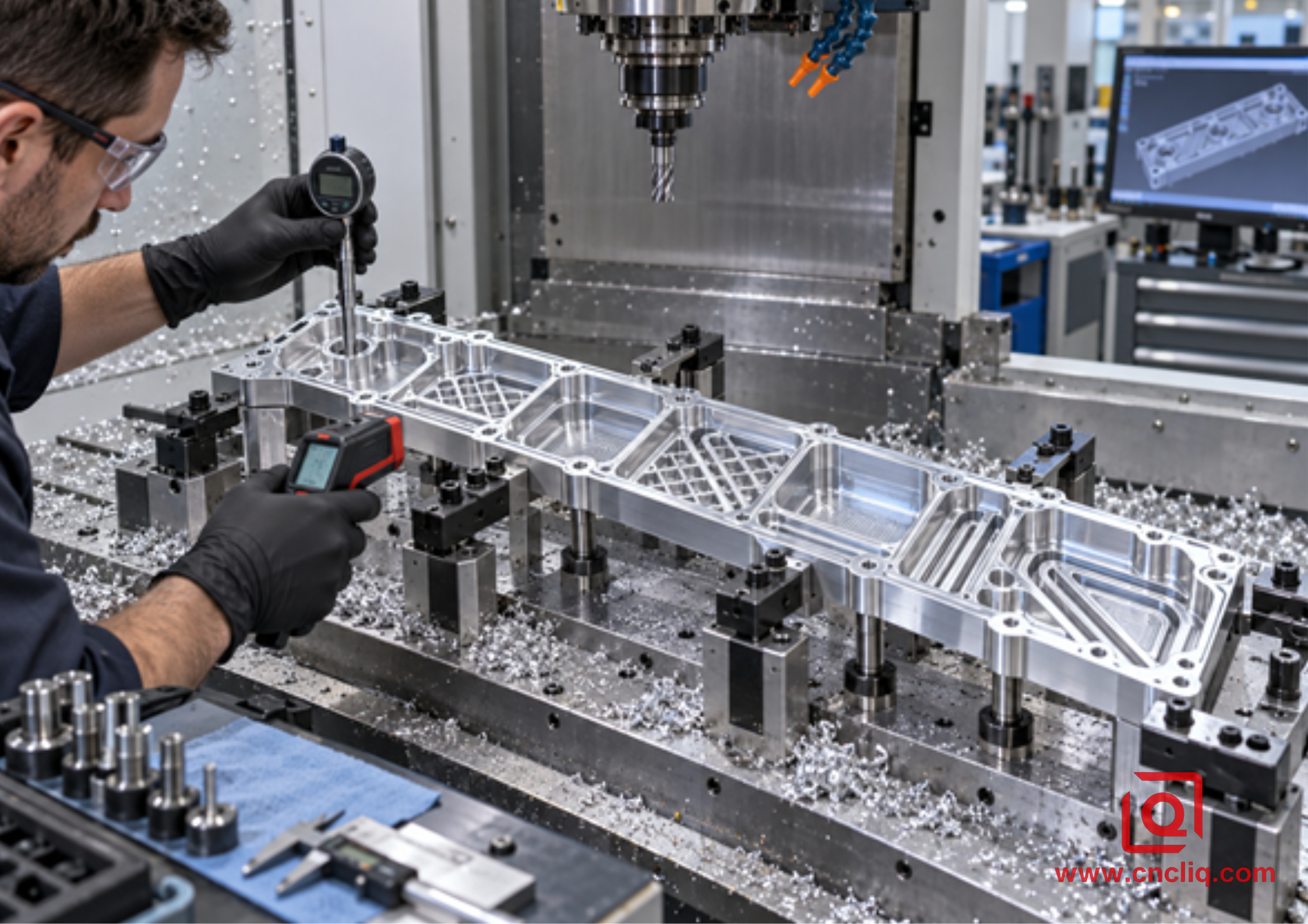
An anonymized industrial electronics buyer requested a custom 6061 aluminum cold plate machined from a rectangular block. The drawing included several deep weight-reduction pockets, a thin base beneath the pockets, mounting bores tied to a common datum structure, and machined passages that would later be sealed and tested. This is an illustrative, sanitized case built around Liqin's verified custom CNC machining scope; it does not report a universal cycle time, tolerance, leakage result, or customer identity.
The initial risk review did not begin with maximum RPM. The team separated the job into a rigid-envelope roughing stage, a balanced pocketing stage, and a controlled finishing stage. A short aluminum-specific cutter and constant-engagement path were selected for open roughing. Stock was retained near the thin base and critical datum areas so they remained supported. Rest machining used a smaller tool only where necessary instead of extending the main cutter to reach every corner.
After roughing, the part was released and checked for movement before the finishing datums were locked. Critical bores and sealing-related surfaces were finished in a controlled sequence, followed by dimensional inspection under the defined condition. The process record tied each approved parameter to the tool ID, overhang, engagement, fixture revision, and inspection checkpoint. This is the practical value of HSM for a B2B program: not a spectacular trial cut, but a traceable method that can be reviewed when the drawing, lot size, or geometry changes.
For a related production example, Liqin's custom aluminum manifold block shows the type of multi-port, multi-datum geometry that benefits from planned roughing, controlled finishing, and documented inspection. A product page is evidence of service scope, not permission to copy its dimensions or process settings into another part.
{width=594 height=420}
11. What to Send for a Fast, Useful Quotation
A supplier cannot quote a controlled HSM route from a screenshot. Send a revision-controlled 3D CAD model and 2D drawing. State the alloy, temper, stock-form requirement, quantity, annual demand, delivery destination, surface treatment, and documentation needs. Identify critical dimensions, GD&T datums, sealing faces, bearing fits, threads, cosmetic zones, edge-break requirements, and surface texture. Note any mating components or assembly function that changes how a feature should be controlled.
If you already have a failed part or unstable process, share the current tool, holder, RPM, feed, ap, ae, toolpath type, overhang, coolant method, fixture concept, failure location, and inspection report. Photographs of chips and the affected surface can help. This information lets an engineering team distinguish a parameter problem from a rigidity, stock, path, or measurement problem.
Need a process-aware review of a 6061 housing, manifold, cold plate, fixture, or structural block? Send the files through Liqin's contact page. Mark the assembly-critical features and target volume. The team can then evaluate manufacturability and prepare a quotation around the actual drawing rather than a generic material table.
FAQ
What is a safe RPM for high-speed machining a 6061 aluminum block?
There is no safe universal RPM. Start with the cutting speed recommended for the exact cutter, calculate RPM from effective diameter, and then check the spindle, holder, balance, overhang, power, engagement, coolant, and fixture. If the machine cannot reach the calculated RPM, use the safe attainable value and recalculate feed so the intended chip load is not changed accidentally.
Should I use 2 or 3 flutes for 6061 block roughing?
A 2-flute end mill offers more chip space and can be useful for full slots, smaller tools, deep pockets, or restricted evacuation. A 3-flute aluminum-specific tool can raise productive feed in open profiling and constant-engagement roughing when the machine is rigid and chips leave freely. Select the exact tool from its application data rather than treating flute count as a standalone rule.
How much radial engagement should an HSM tool use?
Use the radial engagement supported by the exact toolmaker data and CAM strategy for the tool, axial depth, overhang, and material condition. A shallow radial engagement is common in constant-engagement roughing, but the correct percentage is not universal. Review chip thinning, inside corners, rest stock, entry moves, and any place where the cutter can encounter more material than the nominal value.
Why does a 6061 block move after roughing?
Movement can come from residual stress in the stock, an unbalanced removal sequence, loss of section stiffness, excessive clamping force, fixture contact, or a temperature difference between machining and inspection. Confirm material condition, rough opposing regions where practical, retain support near thin features, release and recheck at the planned stage, and define the measurement condition before changing cutting speed alone.
What details most improve a 6061 CNC machining quotation?
Provide 3D CAD and a controlled 2D drawing, alloy and temper, stock-form requirement, quantity, annual volume, GD&T datums, critical fits, threads, surface texture, finish, cosmetic and sealing zones, inspection documents, packaging, and delivery location. If speed or distortion is already a problem, also provide the present tool, holder, overhang, RPM, feed, engagement, coolant, fixture, failure photographs, and inspection data.
Summary
Reliable HSM of 6061 aluminum blocks comes from a verified process window, not a borrowed RPM. Lock the material and feature risks, calculate from tool-specific data, keep engagement and chip evacuation controlled, protect weakening walls and floors, measure under a defined condition, and release production only after a documented first-article review. For an accurate quotation, send the complete CAD, drawing, quantity, material condition, critical features, finish, and inspection requirements.
Contact Information
Company: Ningbo Liqin Industry Co., Ltd.Daily customer maintenance & after-sales support:service@shturl. zhuwanying@cncliq.com
New inquiry, quotation & order discussion:business@shturl. zhouli@chinaliqin.com
Hotline: +86 18757148656
Disclaimer
All technical articles, material specifications, machining recommendations, and surface treatment details published on this blog are for informational and reference purposes only. Please note that general blog insights do not replace signed technical agreements. Because custom parts vary by material heat numbers, machine calibrations, and specific tolerances, binding quality specs are governed solely by your approved CAD drawings, signed contracts, and formal quality plans.
All customer case studies featured on this blog have been thoroughly anonymized and sanitized. The performance metrics, manufacturing workflows, and imagery displayed serve solely to demonstrate our custom machining capabilities and do not represent a single universal standard for all orders.
Liqin Manufacturing Team
Built on 18 years of precision engineering experience, Ningbo Liqin Industry manufactures high-tolerance metal components for demanding global markets. We operate out of a 6,500 m² production hub equipped with over 150 machines, running 4-axis and 5-axis CNC machining, mill-turn machining, cold extrusion, and pressure die casting under one roof. This setup allows us to manage projects seamlessly, taking parts from initial CAD concepts directly to finalized shipments.
We handle quality control with zero compromise. We treat tight tolerances with the engineering discipline they require. Backed by ISO 9001, ISO 13485, and IATF 16949 certifications, our QA engineers run strict IPQC, FQC, and OQC checks on every single production batch. From CMM dimensional mapping and optical profiling to hardness and salt-spray testing, we validate your critical specs upfront—so you receive drop-in ready components with zero assembly headaches or costly line stoppages. On top of manufacturing, you can rely on us for two-hour response times on new RFQs, direct support for prototype sampling, and smooth export shipping across Europe, North America, Asia, and Oceania.
Welcome your inquiries and samples. Visit our website or contact us directly for a competitive quote!
