 English




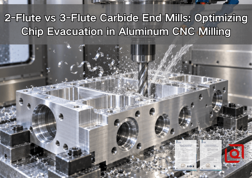
Are you still fighting welded chips, scratched pocket floors, or a cutter that sounds healthy until it snaps inside a deep aluminum slot? This guide explains how to choose between 2-flute and 3-flute carbide end mills from the viewpoint of a production floor—not from a catalog headline. The short answer is simple: choose 2 flutes when chip space is the first constraint; choose 3 flutes when productivity and stability can be gained without trapping chips. The useful answer depends on slot width, radial engagement, tool reach, spindle limits, air or coolant delivery, alloy, and the surface your drawing actually calls for.
This article is for OEM engineers, sourcing teams, and machinists evaluating aluminum CNC milling, custom aluminum parts, and carbide end mill selection. It covers the information, comparison, and RFQ decisions behind the search query “2 flute vs 3 flute end mill for aluminum.” If you need a broader process baseline first, our 6061 aluminum feeds, speeds, and tooling guide explains why every published number must be treated as a starting point and checked against the cutter maker’s data.
Workshop answer in 20 seconds: Start with a 2-flute aluminum-specific cutter for deep full-width slots, enclosed pockets, weak chip flushing, modest-spindle routers, or unusually gummy material. Start with a 3-flute cutter for open side milling, adaptive roughing, profiling, and finishing on a rigid machine with reliable chip removal. Do not choose on flute count alone: edge sharpness, rake, flute polish, helix, runout, stickout, and coolant direction can reverse the result.
Why Aluminum Chip Evacuation Decides the Cut
Aluminum is often described as “easy to machine,” yet that phrase hides the problem that ruins many production runs. Wrought aluminum can be cut at high surface speed and with a healthy chip load, so the cutter creates a large volume of ductile chips very quickly. Those chips must leave before the next cutting edge arrives. If they remain in a slot, they are cut again, rubbed against the wall, or pressed into the flute. Heat and pressure then encourage built-up edge (BUE): a layer of work material adheres to the cutting edge and changes its effective geometry.
Once BUE starts, a sharp edge behaves like a blunt one. Cutting force climbs, the wall finish turns cloudy or torn, burrs grow, and the tool may push away from the programmed path. In a deep pocket the failure can accelerate in seconds because fresh chips have nowhere to go. This is why flute count is really a discussion about chip cross-section, flute valley volume, tooth frequency, and tool core strength.
Harvey Performance’s machining guide notes that aluminum end mills are commonly offered with 2 or 3 flutes because chip valleys shrink as flute count increases, while aluminum tends to generate a relatively large chip. The same source identifies 35°, 40°, and 45° as common aluminum-specific helix angles, with 35°–40° used for traditional roughing and slotting and 45° often used for finishing or high-efficiency toolpaths. Those are useful design patterns, not universal commands; the exact tool series and application sheet still govern the setup. Haas Tooling likewise describes 2 flutes as the long-standing aluminum standard where chip clearance matters, while its 3-flute aluminum designs use geometry and variable pitch to combine evacuation, rigidity, and reduced chatter.
2-Flute vs 3-Flute Geometry: What Actually Changes?
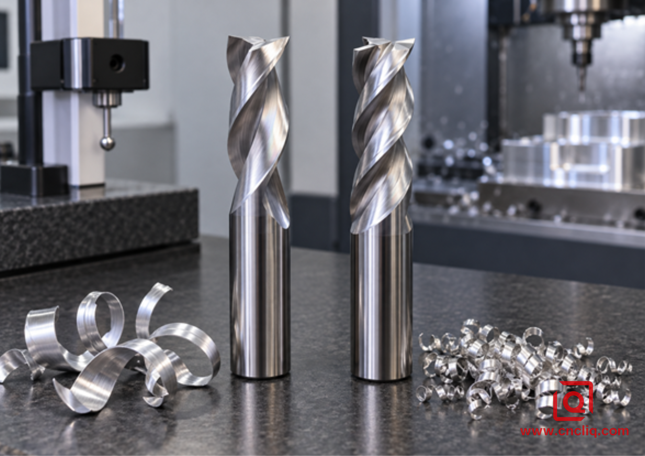
A visual comparison of flute space and chip form; actual cutter geometry varies by manufacturer.
Imagine looking straight at the end of 2 cutters with the same diameter. The 2-flute version usually devotes more of its circumference to open valleys. The 3-flute version divides that circumference among another cutting edge, commonly leaving less room per valley but more core material. “Usually” matters here. A modern 3-flute cutter with an engineered open flute may evacuate better than a generic 2-flute tool with a poor rake face or rough flute finish.
|
Decision factor |
2-flute carbide end mill |
3-flute carbide end mill |
|
Flute valley space |
Largest practical space in a like-for-like design; wider safety margin when chip volume is high. |
Less space per flute, but effective when geometry, engagement, and flushing are controlled. |
|
Teeth entering the cut |
2 engagements per revolution. |
3 engagements per revolution; 50% more tooth passages at the same RPM. |
|
Core and bending stiffness |
Often lower in a comparable design because more cross-section is opened for flutes. |
Often higher, helping wall position and chatter resistance during side cutting. |
|
Feed potential |
Lower table feed at the same RPM and feed per tooth. |
Higher theoretical table feed at the same RPM and feed per tooth, provided chips can escape. |
|
Best starting applications |
Deep slots, full-width cuts, enclosed pockets, weaker evacuation, lower-power or less-rigid machines. |
Adaptive roughing, open pockets, profiling, side milling, semi-finishing, and finishing. |
|
Main risk |
Lower stiffness and fewer tooth engagements can limit feed or wall finish. |
Chip packing can erase the productivity advantage and damage the tool or part. |
A polished flute is not cosmetic. It reduces friction along the chip path and makes adhesion less likely. Aluminum-specific tools also use a sharp edge and positive rake to shear rather than plough. Uncoated, ZrN, TiB2, or certain low-friction coatings may be offered for non-ferrous applications. Select only from the toolmaker’s aluminum recommendation; a coating name by itself does not prove that the edge preparation, substrate, and flute form fit your operation.
The Feed-Rate Advantage of 3 Flutes—With the Math Shown
Flute count directly affects programmed feed because table feed is calculated as:
Feed rate (Vf) = spindle speed (n) × number of flutes (z) × feed per tooth (fz)
Spindle speed can be calculated from metric cutting speed as:
n = (1,000 × cutting speed Vc) ÷ (π × tool diameter D)
Consider an intentionally conservative calculation example for a 10 mm carbide end mill in wrought aluminum. At Vc = 400 m/min, calculated spindle speed is approximately 12,732 RPM. If the selected toolmaker approves fz = 0.05 mm/tooth for the actual engagement, a 2-flute tool calculates to about 1,273 mm/min. A 3-flute tool calculates to about 1,910 mm/min. The 3-flute number is 50% higher because it has 3 teeth instead of 2.
That arithmetic does not promise a 50% shorter cycle. A spindle may be torque-limited; a controller may slow through corners; the tool may require a lower chip load in a full slot; or evacuation may become the bottleneck. The purpose of the calculation is to stop a common mistake: changing from 2 flutes to 3 but leaving table feed unchanged. At the same RPM and feed rate, each 3-flute tooth takes a thinner chip. Excessive chip thinning can turn cutting into rubbing, raising heat and encouraging adhesion.
For a published reference, Haas lists target data for one HSAM2 tool family in wrought aluminum at 2,000 SFM, with chip load changing by diameter. Harvey’s broader guide gives 800–1,500 SFM for wrought 2024, 6061, and 7075 as a general range. The difference illustrates the correct practice: start with the exact cutter’s data, then derate for slotting, reach, fixture compliance, spindle power, and coolant reality. Never paste a speed from a blog into a machine without a controlled prove-out.
When a 2-Flute End Mill Is the Safer Choice
1. Deep, full-width slotting
In a 100% radial-width slot, the cutter is surrounded by material through a large arc. Chips cannot exit freely to the side and must travel through the flute or be blown out of the channel. The extra valley volume of a 2-flute cutter gives the process more tolerance when a nozzle is slightly misaligned or a slot becomes deeper. Use a ramp or helix where geometry allows instead of a straight plunge, and keep the evacuation stream aimed into the cut—not merely at the toolholder.
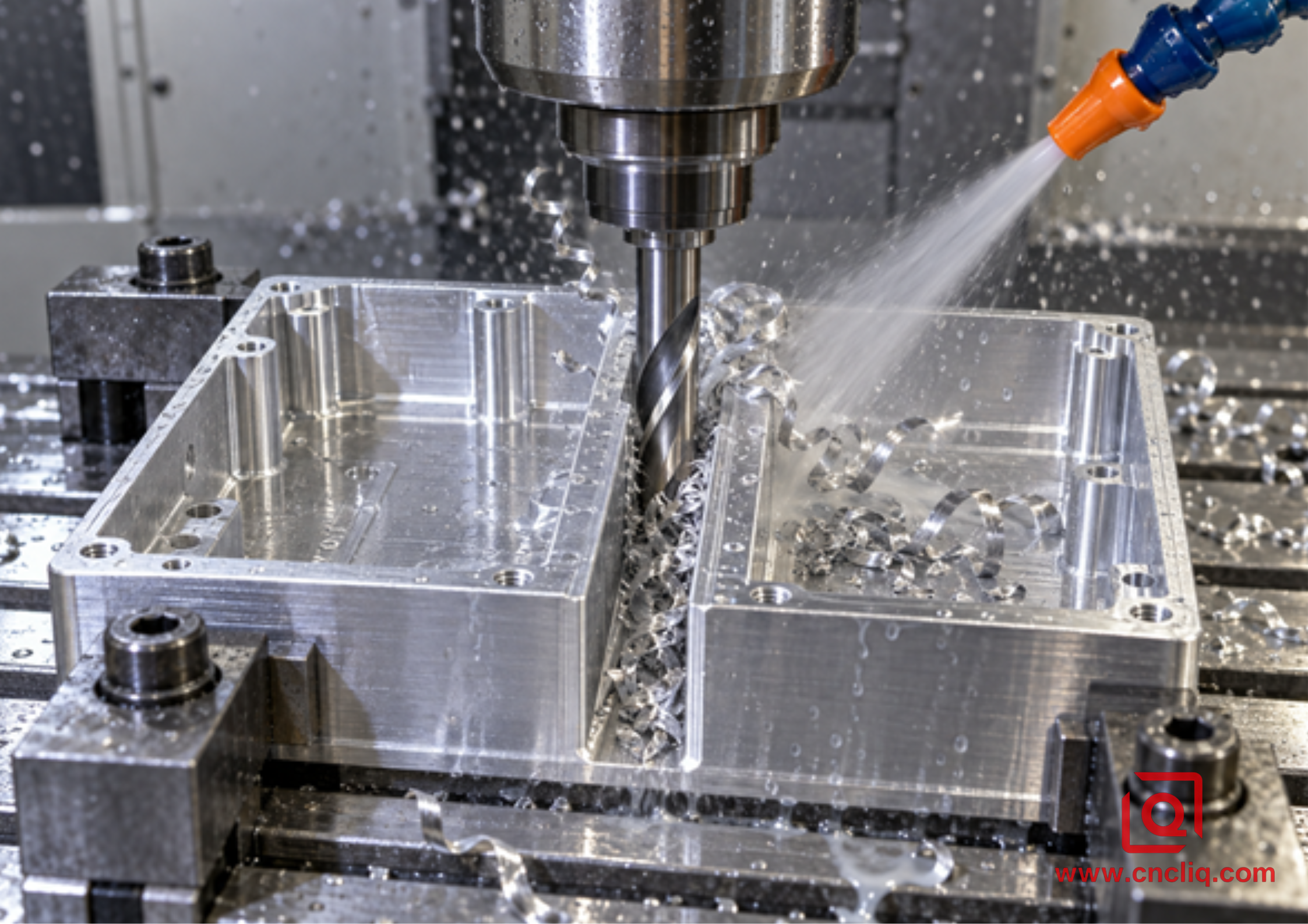
Deep slotting concentrates chip volume; the evacuation stream must reach the cutting zone.
2. Enclosed pockets with poor line of sight
A pocket can look open in CAD yet behave like a chip trap after the tool descends below a rib. If air or coolant cannot reach the bottom, chips circulate around the cutter. A 2-flute tool cannot fix a blocked evacuation path, but it provides more room before packing occurs. Program intermediate lifts or a toolpath that moves chips toward an open side, and verify the result through the machine window during the first safe prove-out.
When a 3-Flute End Mill Earns Its Place
1. Adaptive or high-efficiency roughing
Low radial engagement opens the cut and reduces the volume that each flute must carry at one instant. That is where a well-designed 3-flute carbide end mill can combine a meaningful axial depth with more tooth engagements and higher table feed. The toolpath must control engagement through corners and narrow channels. If it suddenly buries the cutter at 100% width, the “adaptive” setup has lost its evacuation advantage.
2. Side milling and external profiling
With one side of the cutter open, chips can leave radially. The additional flute and typically stronger core can reduce deflection and create more regular contact. That helps hold a wall, particularly when a finish allowance is consistent and stickout is short. If the part includes complex multi-directional walls, our guide to multi-axis CNC milling for complex aluminum OEM parts explains how setup access and tool reach interact with cutter selection.
3. Semi-finishing and finishing
A 3-flute tool often provides better finishing potential, but it does not guarantee a roughness number. Runout causes one flute to carry more load than the others. A worn holder, long projection, recut chips, or too little feed per tooth may still leave vertical bands or a smeared surface. For a serious finish pass, measure tool runout close to the cutting edge, leave uniform stock, use climb milling where appropriate, and keep chips from crossing the finished wall.
A Shop-Floor Selection Matrix
|
Operation or condition |
Starting choice |
Reason and check |
|
Full-width slot deeper than 1×D |
2 flutes |
Maximum chip space. Confirm air/coolant reaches the slot bottom and use the toolmaker’s slotting data. |
|
Shallow slot with strong flushing |
2 or 3 flutes |
Runout, spindle power, desired feed, and the exact flute design may decide. |
|
Adaptive roughing at low radial engagement |
3 flutes |
Higher tooth frequency can raise feed; verify engagement remains controlled through corners. |
|
Open-pocket roughing |
3 flutes |
Good productivity when chips have an escape route; 2 flutes remain safer if chips accumulate. |
|
Long-reach wall milling |
3 flutes, geometry dependent |
A stronger core may help, but shortening reach or changing setup is usually more powerful. |
|
Thin-wall finishing |
3 flutes with light, consistent engagement |
Smoother tooth entry can help; manage wall deflection and avoid repeated spring passes. |
|
Weak air blast or obstructed coolant |
2 flutes, then fix delivery |
More flute room adds margin but does not replace a working evacuation system. |
|
Visible BUE or chip welding |
Diagnose before changing count |
Inspect edge wear, chip load, flute finish, lubricant, nozzle aim, and recutting. |
Chip Evacuation Is a System, Not a Cutter Feature
The best flute count will fail if the rest of the system is neglected. Work through these controls in order:
1. Confirm the material and temper. Do not quote or program “aluminum” as if every grade behaves alike. Ask for a material specification and certificate requirements.
2. Select an aluminum-specific geometry. Look for a sharp edge, positive rake, polished/open flutes, appropriate helix, suitable reach, and a manufacturer recommendation for the alloy and operation.
3. Set real chip load. Calculate feed from RPM, flute count, and fz. If RPM changes, update feed. Correct for radial chip thinning only with a method approved for the toolpath and cutter.
4. Limit engagement. Avoid unexpected full-width burial during an adaptive path. Smooth corners, ramp into stock, and keep radial engagement predictable.
5. Shorten the tool assembly. Tool deflection increases rapidly with overhang. Use only the flute length and reach required by the geometry.
6. Put the evacuation stream at the edge. A large coolant flow aimed above the cut may achieve little. Watch where the jet lands at cutting depth and consider multiple nozzles where walls block one direction.
7. Inspect chips and the cutting edge. Healthy chips should leave rather than form a compacted nest. Stop safely if the edge acquires a bright aluminum cap, the spindle load trends upward, or sound changes sharply.
8. Separate roughing from finishing when needed. A dedicated finish tool avoids carrying a roughing edge and embedded debris across the critical wall.
For downstream appearance and corrosion requirements, cutter choice is only the first stage. The machined surface, edge break, cleaning, and alloy also influence post-processing. See our finishing options for CNC-milled aluminum parts before fixing cosmetic callouts on an RFQ.
Troubleshooting: Read the Cut Before Changing the Tool
|
What you observe |
Likely mechanism |
First practical response |
|
Chips packed into the flute |
Insufficient valley space, excessive engagement, or ineffective flushing. |
Stop safely; clear the tool; improve delivery; reduce engagement; consider 2 flutes. |
|
Bright aluminum welded to the edge |
Rubbing, heat, poor lubrication, worn edge, or unsuitable geometry. |
Restore chip load, replace the damaged tool, check fluid/nozzle, verify aluminum-specific design. |
|
Random scratches on pocket floor |
Recut chips dragged under the tool. |
Move chips out of the pocket, alter toolpath direction, and inspect the bottom edge. |
|
Repeating vertical wall bands |
Runout, chatter, deflection, or tooth-to-tooth load imbalance. |
Measure runout, shorten projection, inspect holder, reduce load, then compare 3-flute finishing. |
|
Tool breaks at slot depth |
Chip packing, sudden engagement, excessive reach, or an already damaged edge. |
Review the final seconds of the path, slot depth, evacuation, spindle load, and tool condition. |
|
Finish worsens after increasing RPM |
Feed was not raised, so chip thickness fell and rubbing increased. |
Recalculate feed from approved fz or return to the validated speed/feed pair. |
Anonymous Composite Case: 6082-T6 Fluid Manifold
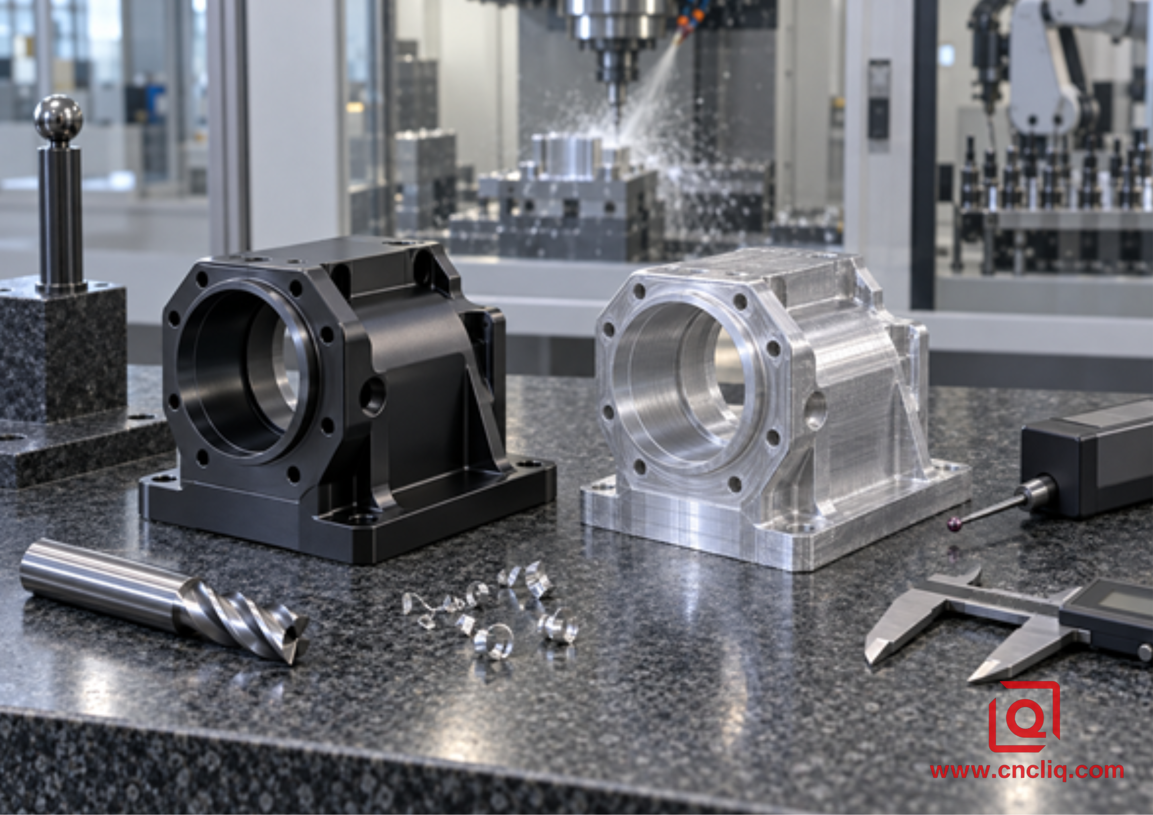
Illustrative inspection scene for a custom aluminum housing/manifold production route.
An anonymized composite buyer needed a compact 6082-T6 pneumatic manifold with deep intersecting ports, an open central pocket, gasket lands, and anodized external surfaces. The component family is consistent with Liqin’s published precision aluminum manifold machining capability, but the example below is sanitized and does not describe one customer’s confidential drawing or universal production standard.
The initial process used one 2-flute tool for nearly all pocket work. It cleared the deepest slot reliably, but open-pocket roughing left unused spindle and feed capacity. The engineering team split the operation. A short 3-flute, polished aluminum cutter handled low-radial-engagement roughing in the open central pocket. The program maintained a controlled engagement angle and directed coolant toward the open side. A 2-flute cutter remained assigned to the narrow, deep full-width channel where chips had only one escape path. Critical gasket lands received a separate finishing pass with uniform allowance after the pocket was clean.
In the composite trial, the mixed-tool strategy reduced the roughing portion of the simulated cycle from 11.8 minutes to 9.6 minutes while eliminating the chip nests seen during the first 3-flute full-slot test. Those figures are illustrative case metrics, not a quotation or guaranteed outcome. The transferable lesson is more valuable: one part may need both flute counts because tool selection belongs to the feature, not to the material name alone.
Inspection focused on datum position, pocket depth, sealing-land flatness, port location, thread condition, and visual damage before anodizing. That approach reflects a broader rule in aluminum CNC milling for OEM parts: machining parameters, tolerance strategy, and the inspection plan must be agreed together. A fast toolpath has no commercial value if the finished component does not assemble or seal.
Planning a custom aluminum housing, manifold, bracket, or robotics component? Send the alloy and temper, STEP file, 2D drawing, annual volume, finish, critical tolerances, and target delivery to Liqin. Our engineering team can review pocket access, cutter reach, datum strategy, inspection needs, and whether a 2-flute/3-flute split is sensible before quotation. Request a manufacturing review and competitive quote.
What to Include in an RFQ for Aluminum CNC Milling
A supplier cannot price chip control from a screenshot. A useful RFQ should include the native 3D model and a controlled 2D drawing, with material grade and temper, general and critical tolerances, datum scheme, surface roughness only where functional, thread standards, deburring expectations, coating or anodizing specification, cosmetic zones, inspection documents, prototype quantity, production forecast, and packing needs. Identify any deep slots or thin walls that drive the process.
FAQ
1. Is a 2-flute or 3-flute end mill better for 6061 aluminum?
A 2-flute tool is the safer starting point for deep full-width slots, enclosed pockets, or weak chip removal because it normally provides more flute space. A 3-flute aluminum-specific cutter is often more productive for adaptive roughing, open pockets, profiling, and finishing because the extra edge raises tooth frequency and may improve core stiffness. The exact cutter geometry, stickout, machine rigidity, engagement, and coolant delivery matter more than a blanket rule.
2. Can a 3-flute carbide end mill cut a full slot in aluminum?
Yes, if the manufacturer rates that tool for slotting and the slot depth, chip load, engagement, and evacuation system remain within its limits. Shallow slots with strong flushing can run well with 3 flutes. As the slot becomes deeper or chips lose an exit path, a 2-flute cutter usually offers a wider process window. Always use the specific toolmaker’s slotting data and prove the cut under supervision.
3. Why did aluminum weld to my cutter even though I used 2 flutes?
Flute count cannot prevent adhesion by itself. Check whether feed per tooth became too small, the edge is worn, the flute surface is unsuitable, the tool is recutting trapped chips, or coolant and air are missing the cutting edge. Also confirm the alloy and temper. Once aluminum has welded to an edge, replacing the damaged cutter is often necessary after the underlying cause has been corrected.
4. Does a 3-flute end mill always give a better surface finish?
No. It offers more engagements per revolution and often a stronger core, so it can improve finishing potential in a stable side cut. However, holder runout, uneven tooth loading, excessive reach, chatter, worn edges, recut chips, and nonuniform finish stock can overwhelm that advantage. Measure the setup and clean the cutting zone before treating another flute as the solution.
5. What information does Liqin need to quote a custom aluminum CNC-milled part?
Provide a STEP model and controlled 2D drawing, material and temper, quantities, critical tolerances and datums, thread and roughness requirements, surface finish, cosmetic zones, inspection or certification needs, and delivery target. For difficult pockets, note depth, minimum internal radius, thin-wall regions, and any prior chip or tool-life issue. That information supports DFM review, process selection, realistic lead time, and a quotation with fewer assumptions.
Summary
Choose a 2-flute carbide end mill when aluminum chip volume, deep slotting, enclosed geometry, or weak flushing makes evacuation the primary risk; choose a 3-flute cutter when open engagement, machine rigidity, and controlled chip removal allow its extra tooth and stronger core to improve feed potential, wall stability, or finish. Calculate feed from RPM × flutes × feed per tooth, use the exact toolmaker’s data, keep stickout short, aim coolant or air at the cutting edge, and judge the process by chips, load, sound, tool condition, and inspected parts. For custom OEM work, the best answer may use both flute counts on different features of the same component.
Contact Information
Company: Ningbo Liqin Industry Co., Ltd.
Daily customer maintenance & after-sales support:service@shturl. zhuwanying@cncliq.com
New inquiry, quotation & order discussion:business@shturl. zhouli@chinaliqin.com
Hotline: +86 18757148656
Disclaimer
All technical articles, material specifications, machining recommendations, and surface treatment details published on this blog are for informational and reference purposes only. Please note that general blog insights do not replace signed technical agreements. Because custom parts vary by material heat numbers, machine calibrations, and specific tolerances, binding quality specs are governed solely by your approved CAD drawings, signed contracts, and formal quality plans.
All customer case studies featured on this blog have been thoroughly anonymized and sanitized. The performance metrics, manufacturing workflows, and imagery displayed serve solely to demonstrate our custom machining capabilities and do not represent a single universal standard for all orders.
Liqin Manufacturing Team
Built on 18 years of precision engineering experience, Ningbo Liqin Industry manufactures high-tolerance metal components for demanding global markets. We operate out of a 6,500 m² production hub equipped with over 150 machines, running 4-axis and 5-axis CNC machining, mill-turn machining, cold extrusion, and pressure die casting under one roof. This setup allows us to manage projects seamlessly, taking parts from initial CAD concepts directly to finalized shipments.
We handle quality control with zero compromise. We treat tight tolerances with the engineering discipline they require. Backed by ISO 9001, ISO 13485, and IATF 16949 certifications, our QA engineers run strict IPQC, FQC, and OQC checks on every single production batch. From CMM dimensional mapping and optical profiling to hardness and salt-spray testing, we validate your critical specs upfront—so you receive drop-in ready components with zero assembly headaches or costly line stoppages. On top of manufacturing, you can rely on us for two-hour response times on new RFQs, direct support for prototype sampling, and smooth export shipping across Europe, North America, Asia, and Oceania.
Welcome your inquiries and samples. Visit our website or contact us directly for a competitive quote!
