 English




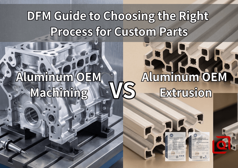
Key Takeaways:
-
Process Crossover Threshold: Machining wins on rapid iteration below 500 units; extrusion slashes piece-part costs by up to 70% once custom die tooling ($2,500–$8,000) amortizes past 1,500 units.
-
Tight Wall Tolerance Strategy: Native profile extrusion holds ±0.15–±0.30 mm (per ISO 2768-m/EN 755-9); secondary 5-axis CNC machining is mandatory for ±0.015 mm bearing journals and O-ring seal grooves.
-
Stress Management: Unsymmetric 6063-T6 extrusions deform up to 1.8 mm over 1,000 mm lengths when skin stress relaxes during aggressive milling—mitigate with vibratory stress relief or post-machining straighten-press ops.
Stop Burning Budget on the Wrong Process Path
We’ve seen it dozens of times in the shop: an engineer drops a STEP file for a 600 mm avionics enclosure rail specified as a solid billet CNC hog-out, expecting 500 pieces in three weeks. They’re burning 82% of an AL6061-T6 block into chips, running a 42-minute cycle on a 12,000 RPM spindle, and wondering why per-unit quotes touch $185. Reverse that approach: extrude the profile, pull 6063-T6 through a tungsten carbide die, and run a secondary 3-axis operation just for the mounting holes and datum faces. Unit price drops to $34, even after amortizing the $3,200 steel die.
Choosing between full-spec OEM CNC machining and aluminum extrusion isn't an academic exercise—it’s about balancing yield strength, thermal expansion, cycle time, and capital layout against raw material removal rates (MRR).
The Raw Data: Process Capabilities & Parameter Matrix
Before locking down your DFM callouts, benchmark your part geometry against real-world shop-floor metrics.
| Performance / Cost Metric | Full CNC Machining (3/4/5-Axis) | Aluminum Profile Extrusion (Native) | Extrusion + Secondary CNC Finishing |
| Primary Alloy Options | AL6061-T6, AL7075-T6, AL2024-T3 | AL6063-T5/T6, AL6005A-T6 | AL6063-T6, AL6005A-T6, AL6061-T6 |
| Dimensional Tolerance | ±0.010 mm to ±0.025 mm (ISO 2768-f) | ±0.15 mm to ±0.50 mm (EN 755-9 / ISO 2768-m) | Profile: ±0.20 mm; Machined: ±0.012 mm |
| Minimum Wall Thickness | 0.8 mm (requires custom damping) | 1.2 mm (solid); 1.5 mm (hollow) | 1.2 mm profile wall; localized to 0.8 mm |
| Surface Roughness (Ra) | Ra 0.8–1.6 µm | Ra 3.2–6.3 µm (die lines visible) | Ra 0.8 µm milled; Ra 3.2 µm body |
| NRE / Tooling Cost | $0 (modular soft jaw fixtures) | $2,200 – $7,500 (H13 steel die) | $2,200 – $7,500 (Die) + $800 (Fixtures) |
| Optimal Economic Run | 1 to 500 pieces | 2,000+ meters / 5,000+ pieces | 800 to 50,000+ pieces |
Where Machining Wins: Multi-Axis Complexity and Material Strength
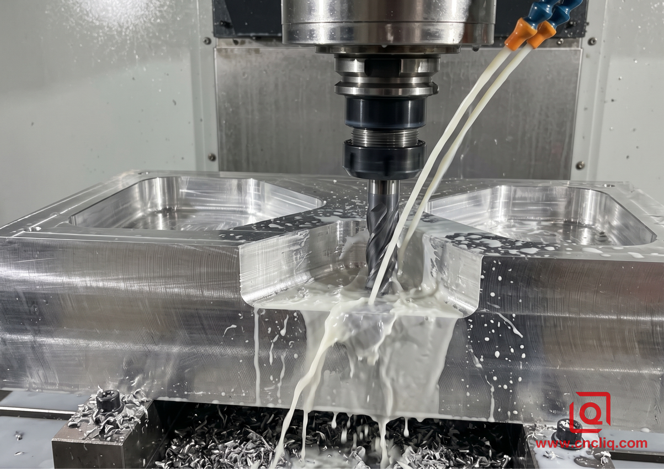
When your enclosure requires 7075-T6 structural integrity—yielding a tensile strength exceeding 505 MPa versus 6063-T6’s 215 MPa—extrusion isn't even in the room. High-stress aerospace brackets, manifold blocks with intersecting internal hydraulic galleries, or deep thin-walled housings demanding internal corner radii under R0.5 mm belong exclusively on a multi-spindle machining center.
Shop-Floor Reality Check: Thin-Wall Chatter & Thermal Drift
Cut AL6061-T6 at a feed rate of 3,200 mm/min with an end mill, and heat builds fast. If coolant pressure dips below 20 bar, chip packing occurs in deep pockets, driving local workpiece temperatures up to 140°C. Because aluminum’s coefficient of thermal expansion (CTE) sits at roughly 23×10-6/K, a 300 mm aluminum housing expands by over 0.08 mm during machining. Unclamp it, let it cool to a 20°C ambient CMM room, and your hole centers collapse out of the ±0.02 mm spec.
Your Actionable Fixes:
-
Flood the cut with a high-pressure (≥70 bar) water-soluble synthetic coolant at an 8–10% concentration to flush chips and maintain thermal stability.
-
Rough out the cavity leaving 0.5 mm stock on all walls, then unclamp the part for a 2-hour stress-relief pause before running light 0.08 mm finishing passes.
-
Keep wall height-to-thickness ratios below 10:1. Need an 80 mm deep wall? Make it at least 8.0 mm thick at the root to prevent cutter chatter.
Where Extrusion Wins: Linear Uniform Profiles and Volume Economics
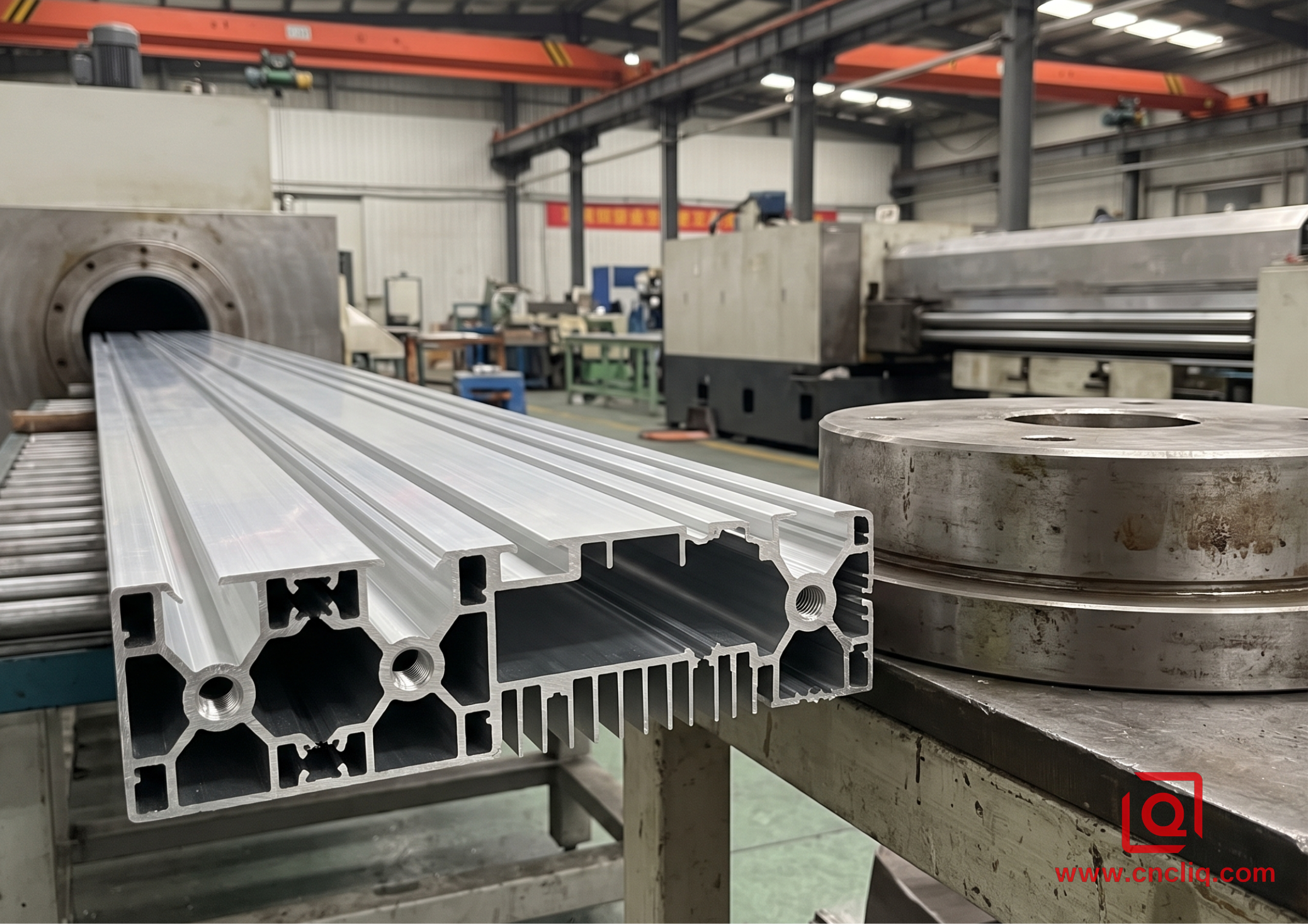
When geometry extends uniformly along a single axis—heat sinks, mounting rails, motor housings—extrusion completely outclasses billet machining. Heating an AL6063 billet to 480°C and forcing it through an H13 tool steel die at 25 bar pressure forms intricate internal channels, screw bosses, and T-slots in a single stroke.
Shop-Floor Reality Check: Skin Tension & Profile Bowing
Extruded 6063-T6 profiles arrive with residual stress distributions caused by uneven cooling fan speeds on the run-out table. Cut a 12 mm slot straight down the center of an unsymmetric hollow extrusion, and the profile immediately bows inward by up to 1.5 mm over a 500 mm span as internal stresses release.
Your Actionable Fixes:
-
Mandate a 1.2% to 1.8% mechanical stretch-straightening operation immediately post-quench, prior to artificial aging (175°C for 8 hours for T6 temper).
-
Maintain symmetric wall thickness across the profile cross-section; never transition from a 5.0 mm outer wall directly to a 1.2 mm internal rib without an R2.0 mm fillet radius.
-
Allow EN 755-9 commercial tolerances (±0.25 mm to ±0.40 mm) on raw profile contours, using post-machining only where mating faces connect.
The Hybrid Master Plan: Extrude the Profile, Machine the Criticals
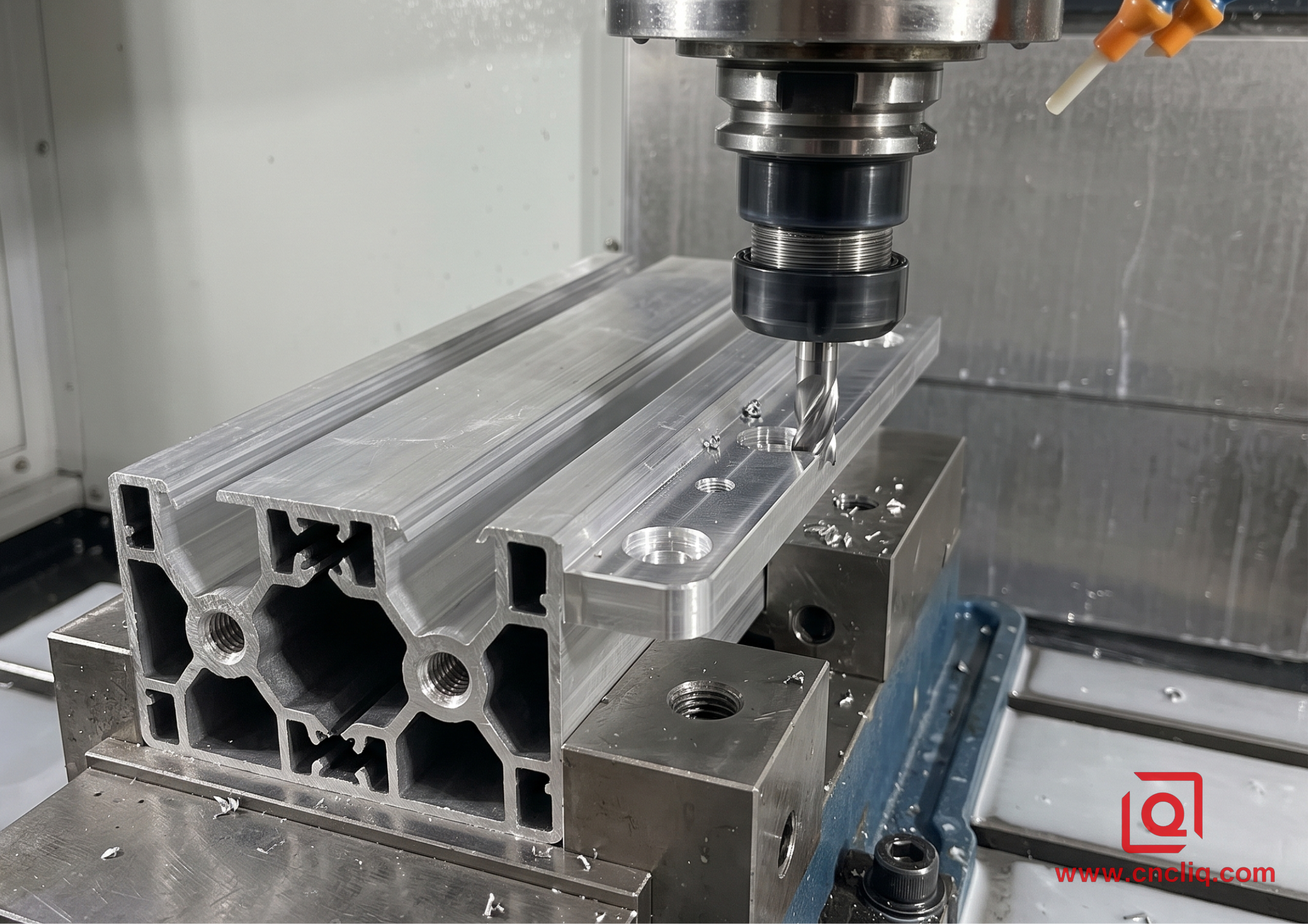
For 80% of OEM applications, the most cost-effective path is a hybrid process: custom extrusion to establish the macro-geometry, followed by secondary CNC operations for precise interfaces.
Step-by-Step OEM DFM Workflow:
-
Lock Down Datums Early: Choose a robust extruded surface as your primary datum (Datum A) rather than an unmachined thin web that flexes under clamping.
-
Account for Anodize Buildup: Type II sulfuric anodizing adds 10–15 µm of oxide layer (50% penetration, 50% growth). Type III Hardcoat adds 40–50 µm. If your bearing bore is callouted at ∅30.000 +0.010/-0.000 mm, machine the raw bore to ∅30.020 mm before anodizing to prevent press-fit rejections.
-
Consolidate Fastener Features: Instead of drilling and tapping M5 holes into solid walls, design extruded screw channels into the profile die. Thread-forming trilobular screws driven straight into extruded ∅4.35 mm bosses eliminate tapping operations while boosting strip-out torque by 25%.
-
Standardize Corner Radii: Match internal pocket radii to standard carbide tool diameters. Avoid R3.0 mm corners that force a 6 mm end mill to chatter at the apex; call out R3.5 mm instead so the tool glides around the corner without stopping.
FAQs
Q1: Why do our thin-walled extrusion profiles twist or warp after secondary CNC milling, and how do we prevent it?
A: When you aggressively mill away the hardened outer skin of an aluminum extrusion, you upset the delicate balance of internal residual stresses created during the quenching and cooling phase at the mill. The metal essentially relaxes into a new shape, causing the part to twist or bow once unclamped. To prevent this on the shop floor, we mandate mechanical stretch-straightening right after extrusion quench, before artificial aging. For critical parts, run a rough machining pass on all critical surfaces, unclamp the workpiece to let internal stresses dissipate naturally, and then execute a tension-free light finish pass using low-force clamping techniques.
Q2: How does material selection change if we switch from solid billet CNC machining to profile extrusion?
A: Billet machining offers free rein over high-strength, copper- or zinc-heavy alloys like aerospace-grade 7075 or 2024, which deliver massive structural rigidity but resist being forced through extrusion dies. When transitioning to extrusion, you typically move toward magnesium-silicon 6000-series alloys like 6063 or 6005A. These flow predictably through die apertures, yield glass-smooth surface finishes, and form intricate hollow geometries, all while retaining excellent anodizing responsiveness and respectable post-aging yield strength for structural housings and frames.
Q3: Should we machine thread holes directly into extruded parts, or are there smarter fastener integration strategies?
A: Drilling and tapping blind or through-holes into extruded walls wastes valuable machine cycle time and risks thread stripping in softer aluminum alloys. A superior DFM approach involves incorporating continuous screw channels directly into the extrusion die profile. By utilizing thread-forming, trilobular fasteners driven straight into these molded channels, the screw cold-works the aluminum material into dense, high-strength threads without generating chips, dramatically improving joint pull-out resistance while eliminating drilling and tapping operations altogether.
Q4: How do we handle tight tolerance fits on raw extrusions when anodizing or hardcoating is required?
A: Anodizing isn’t just a surface color change; it converts parent aluminum into an oxide layer that physically grows outward while consuming internal base metal. If you machine a bearing bore or sliding fit to exact nominal drawing dimensions prior to surface treatment, the dimensional buildup from Type II or Type III hardcoating will inevitably result in press-fit failure or binding shafts. Your engineering drawings must specify pre-plate machining dimensions that account for this predictable coating growth, ensuring functional tolerances are met only after the final electrochemical bath.
Q5: What is the most effective way to establish reliable machining datums on raw aluminum extrusions?
A: Never select an unmachined, thin-walled feature or an unsupported cantilevered rib as your primary machining datum—the clamping pressure alone will flex the part, causing geometric errors as soon as the vise relaxes. Instead, select thick, fully supported structural walls or flat base profiles as your primary datum surfaces. If the raw profile draft or surface waviness prevents repeatable seating in soft jaws, incorporate sacrificial tooling lugs or pre-machine three dedicated locating pads in your first setup to establish a rock-solid, vibration-free coordinate system for all subsequent toolpaths.
Make the Right Process Call
Stop letting unoptimized CAD files eat your margins. If you're building prototypes or runs under 300 pieces with complex multi-axis geometric tolerances, cut them directly from AL6061-T6 or AL7075-T6 billet on a 5-axis center. If you're scaling past 1,000 units and the cross-section is uniform, invest $3,500 in a hardened H13 extrusion die, extrude in AL6063-T6, and let a high-speed 3-axis CNC finish the precision mating faces.
Got a complex OEM aluminum drawing on your desk right now? Send your 3D STEP files and 2D engineering drawings to our engineering team today for a complete DFM analysis and multi-process cost breakdown within 24 hours.
Contact Information
Disclaimer
Liqin Manufacturing Team
We are Ningbo Liqin Industrial & Trading Co., Ltd.,a professional manufacturer with over 18 years of experience in high-precision custom metal parts. We specialize in CNC machining, forging, die casting, and cold extrusion processes, serving industries such as automotive, medical, aerospace, electronics, and more. Our factory covers an area of 6,500 square meters and is equipped with 150+ advanced machines, including:
- CNC machining centers (4-axis, 5-axis)
- CNC lathes and turning-milling complexes
- Cold extrusion equipment (250T–650T)
- Die casting machines
We adhere to ISO9001, ISO13485: 2016, and IATF16949: 2016 standards, implementing end-to-end quality management: In-process quality control (IPQC), final quality control (FQC), outgoing quality control (OQC). CMM, projectors, hardness testers, and salt spray test equipment. Our products are exported to North America, Europe, Asia, and Oceania. We offer:
- One-stop service from design to delivery
- Quick response within 2 hours for quotes and technical support
- Custom solutions based on your drawings or samples
Welcome your inquiries and samples. Visit our website or contact us directly for a competitive quote!
