 English





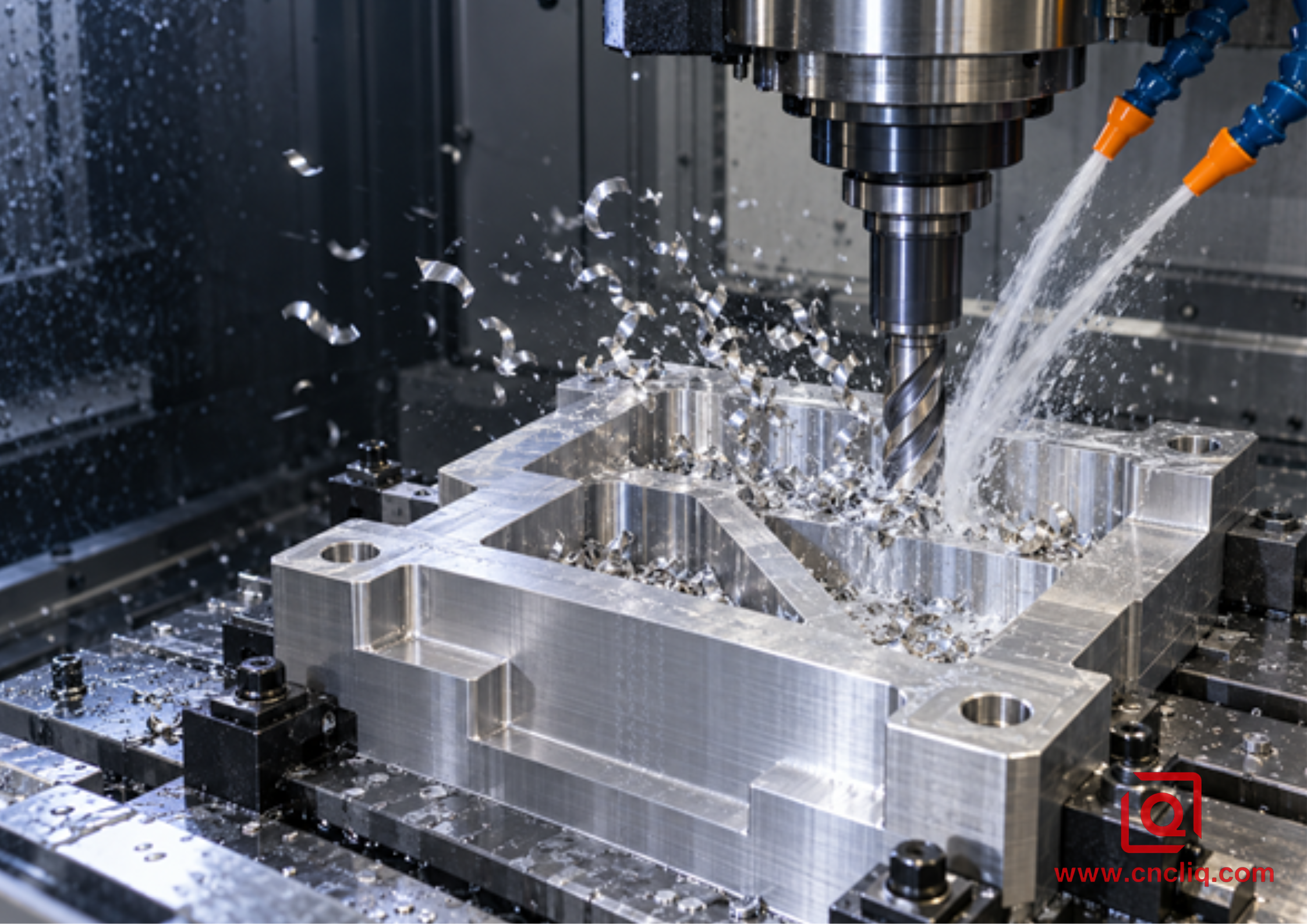
Are you still losing tools near the bottom of an aluminum pocket even though the first few levels cut cleanly? The spindle note changes, bright chips stop leaving the cavity, and the floor begins to look as though it has been rubbed with gray paste. That is not a mysterious material problem. It is usually a transport problem: the machine is making chips faster than the pocket, tool, and fluid path can remove them.
This guide shows how to build chip evacuation into deep pocket aluminum milling from the start. It is written for manufacturing engineers, machinists, and B2B buyers who need more than a catalog answer. We will map the chip route, match the cutter to the available space, aim coolant or air at the working depth, use gravity when the machine allows it, and verify the result before a long production run. You will also see what to include in an RFQ so a custom aluminum CNC machining supplier can quote the real process instead of adding risk to the price.
Fast Answer: Build an Exit Route, Not a Bigger Splash
A reliable deep-pocket process does 5 things together:
1. It creates chips that fit the flute and can move.
2. It leaves open space around the cutter.
3. It sends a coherent coolant or air stream to the active edge at maximum depth.
4. It carries used fluid and chips out of the pocket instead of recirculating them.
5. It cleans and verifies the cavity before finishing.
More coolant is not a specification. A large flood hitting the holder can look impressive while the cutter works in a stagnant bed. Pressure, flow, direction, filtration, alloy, tool geometry, toolpath, pocket shape, and machine orientation are one system. Start with the cutter and fluid supplier's current data, then prove the deepest and most enclosed cut on the real machine.
1. Why Evacuation Gets Worse with Every Level
Aluminum is often called easy to machine because a sharp tool can remove it quickly. That same productivity creates a high chip volume. The chips are light and ductile. They can curl into springs, bridge between ribs, wrap around a holder, or flatten into thin pieces that are easy to recut.
At the top of a pocket, the chip has several escape directions. As the tool descends, the walls block lateral motion. The holder shadows the nozzle. A blind floor prevents downward flow. Ribs split the cavity into small cells. A return stream may lift chips halfway up and drop them directly back into the cut.
When the next edge meets an old chip, it no longer sees the programmed chip thickness. The chip can be hammered into the wall, dragged across the floor, or pressed into a flute. Friction and pressure encourage built-up edge, or BUE, where work material adheres to the cutting edge. The effective edge becomes rounder, cutting force increases, finish deteriorates, and the packed flute can fail abruptly.
Watch the transition, not just the final alarm. Useful signs include:
· spindle load rising at the same Z level on each part;
· chips orbiting the holder instead of reaching the conveyor;
· one corner collecting a wet nest;
· a sharp cut changing to a muffled or grinding sound;
· bright chips becoming flattened, smeared, or repeatedly folded;
· cloudy vertical streaks on a wall;
· chips stuck to only 1 flute, which may also indicate runout.
2. Map the Chip Route Before CAM Programming
Take a pocket section view and draw 3 paths: incoming fluid or air, outgoing chips, and returning fluid. If the outgoing path crosses the incoming jet, or both paths end in the same blind corner, the design has a circulation loop rather than an evacuation route.
Ask these questions during DFM:
· Is the pocket open on any side?
· Can a through-hole or temporary window provide a downward outlet?
· Do internal ribs divide the cavity into isolated cells?
· Does the fixture block the most natural exit?
· Can the part tilt so gravity assists removal?
· Can a larger internal radius permit a larger, stiffer cutter and more clearance?
· Which walls and floors are functional, and which are only clearance surfaces?
· Will chips be trapped again during drilling, tapping, washing, or anodizing?
The Sandvik Coromant groove and slot milling guide advises minimizing overhang, using the largest practical tool, and ensuring that chips leave the groove. It describes trochoidal milling as providing good chip evacuation and states that, for that method, cutter diameter should be no more than 70% of slot width. ISCAR's published pocket guidance recommends opening from the middle and continuing with shoulder milling to improve chip evacuation and reduce corner vibration. These are not universal parameter recipes. They support a broader rule: preserve open space around the tool and move debris toward a known outlet.
|
Pocket condition |
Evacuation objective |
Practical direction |
Verification point |
|
Open pocket with side access |
Push chips toward the opening |
Work from closed areas toward the open side |
No pile behind the cutter |
|
Wide blind pocket |
Lift chips before they settle |
Open a central volume, then expand outward |
Floor is visible after a safe stop |
|
Narrow deep slot |
Preserve flute and side clearance |
Use a smaller approved cutter and controlled engagement |
No packed chip ribbon in the slot |
|
Ribbed enclosure |
Give each cell its own flow path |
Machine accessible cells first and redirect the jet for each cell |
Every cell clears at maximum depth |
|
Through-pocket |
Use the lower opening safely |
Provide a fixture gap and protected fall path |
Chips do not catch below the part |
|
Thin-wall cavity |
Evacuate without moving the wall |
Balance stock removal and avoid direct jet force on weak walls |
Wall profile remains stable |
If multi-face access lets the spindle use a shorter tool and point the opening downward, review the multi-axis CNC milling guide for complex aluminum geometries. A 5-axis label alone adds no value; the benefit comes from a measurable reduction in reach, setups, or chip trapping.
3. Match Cutter Geometry to Chip Volume
For deep aluminum roughing, 2-flute and 3-flute carbide end mills are common starting points. A 2-flute cutter normally provides larger flute valleys. That extra space helps in full-width slots, enclosed pockets, weak flushing, or gummy material. A 3-flute aluminum-specific cutter can offer more tooth engagements and a stronger core when an adaptive side cut and dependable evacuation leave enough room for the chip.
The detailed choice is covered in Liqin's 2-flute versus 3-flute aluminum end-mill guide. For this article, the key is simple: flute count cannot replace a transport path. Inspect the whole tool:
· sharp positive cutting edge for non-ferrous material;
· open, polished flute surface;
· flute length that covers the intended axial cut;
· neck clearance that does not rub the wall;
· core strength suitable for the projection;
· center-cutting capability if the entry requires it;
· internal coolant outlets that aim where the operation needs them.
Keep gauge length only as long as the geometry requires. Rough the accessible volume with a short tool, then introduce long reach only for residual stock. Measure runout near the cutting edge. If 1 flute carries most of the load, its chip is larger than the calculated average and may weld first.
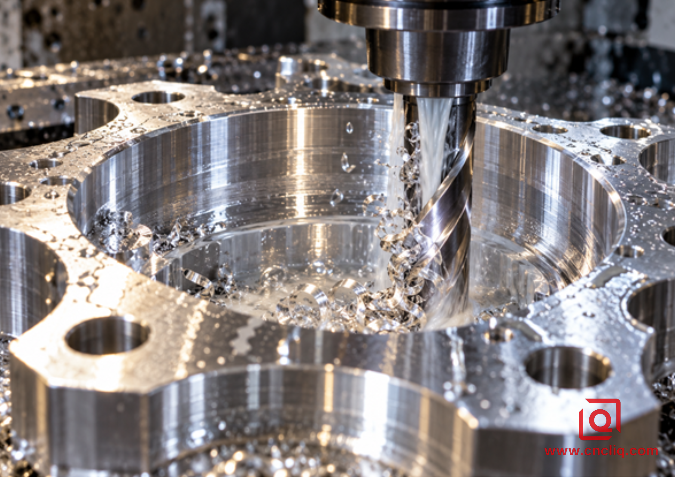
Through-tool coolant evacuating chips from a circular deep aluminum cavity
The stream must reach the flute exit at working depth, not merely wash the top rim.
4. Create Space Before Chasing Material Removal Rate
A conventional offset path can bury the cutter in corners and push loose chips toward the last closed area. In deep pocket CNC milling, the first roughing goal is to create a roomy transport channel. Open a central region with a short, rigid tool, then expand toward the planned exit.
Constant-engagement paths are useful because they limit sudden radial load changes and repeatedly give the edge open space. Mentioning adaptive or trochoidal motion does not mean the strategy should copy the existing article on trochoidal milling. Here it is 1 element in a larger evacuation system. The CAM path must still direct chips away, avoid re-entering a pile, and respect acceleration limits.
Use a helical or ramp entry only when the cutter is approved for it. Avoid a straight plunge unless the tool is center-cutting and the axial load and chip path have been verified. At depth, a safe programmed retract can let a flush cycle work without the rotating tool grinding the floor. Do not dwell at the bottom and hope the fluid catches up.
A practical sequence is:
1. Face and establish reliable datums.
2. Open a central volume with the shortest suitable rougher.
3. Expand from the center toward the chosen chip exit.
4. Divide depth into bands that the real jet can clear.
5. Rest-machine only the remaining stock with the long-reach tool.
6. Retract to a defined safe level for any programmed flush or inspection.
7. Clean and inspect the cavity before semi-finishing.
8. Use isolated finish passes on known, uniform stock.
5. Engineer the Coolant or Air Path at Maximum Depth
A nozzle position that works near the top may be useless 40 mm lower. The holder, a pocket wall, or a rib can shadow the cutting edge. Verify delivery at shallow, middle, and maximum working depth. A coherent jet should reach the flute exit and carry the chip toward open space.
Through-spindle or through-tool coolant can help because delivery follows the cutter, but internal coolant is not an automatic solution. Outlet size and direction must suit the tool. A stream that pushes chips deeper into a blind corner may worsen packing. External nozzles remain effective when they are stable, accurately aimed, and not knocked out of position during loading or tool changes.
Sandvik Coromant's milling application guidance specifically recommends compressed air to prevent chip recutting in deep-cavity milling. Air blast or minimum-quantity lubrication must still comply with tool guidance, enclosure design, mist extraction, fire controls, and local safety rules. Never improvise a flammable liquid inside an enclosed machine.
For flood coolant, follow the fluid suppliers concentration, water-quality, filtration, and maintenance instructions. Use the correct refractometer factor. A concentration copied from another factory is not a quality plan. Weak or contaminated fluid can reduce lubricity and stain parts; an excessively rich mix can leave residue, raise cost, and create operator-exposure concerns.
Perform a return-flow test. At a safe machine state, observe not only where the jet enters but where fluid and chips leave. If chips rise, circle, and fall back, add a secondary directional jet or change the cutting sequence. The second jet should break the loop, not simply make more turbulence.
6. Use Orientation, Gravity, and the Conveyor as Part of the Process
A vertical machining center makes a blind pocket behave like a bucket. Chips must climb before they can leave. On a horizontal machining center, a vertically mounted workpiece may let debris fall away from the active cut and toward the auger. A trunnion or indexed 5-axis setup can create a similar advantage by tilting the opening.
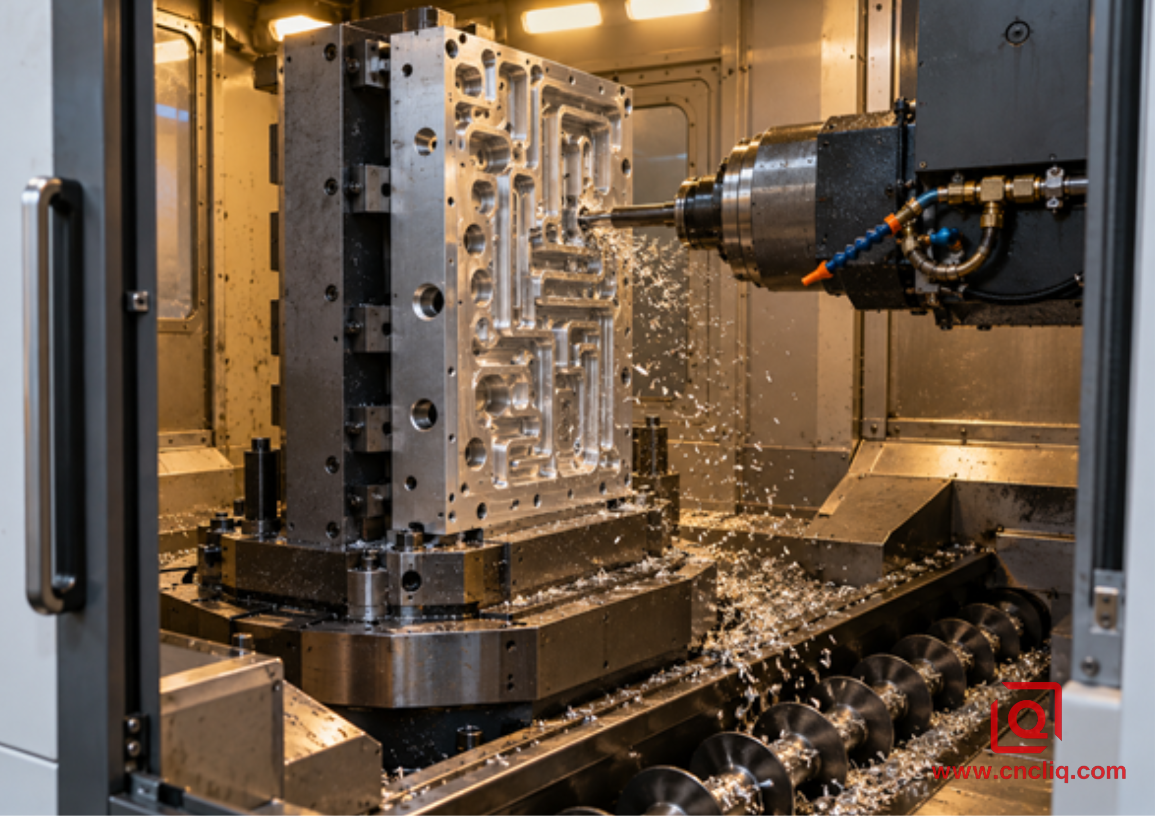
Horizontal machining center using gravity-assisted aluminum chip evacuation
The pocket, fixture, enclosure, and conveyor must form one continuous chip route.
7. Keep Roughing Debris Away from Finishing
Bulk removal and final surface generation need different conditions. Roughing creates the most chips and tolerates a controlled allowance. Finishing needs clean walls, a clean floor, uniform stock, low runout, and a verified edge.
Then finish functional walls, floors, sealing lands, or bearing features with isolated passes. Do not chase a bright cosmetic surface in a hidden clearance pocket if the drawing does not require it. A recut chip can scratch a floor after the dimensional work is already correct, so cleaning is a process stage rather than housekeeping.
Thin walls require extra care. Rough while surrounding material still supports them. Remove stock in a balanced sequence, and finish tall walls in controlled axial bands when appropriate. Do not point a high-energy jet directly at a flexible wall without verifying that it does not move. Chip evacuation can reduce heat and recutting, but it cannot eliminate distortion from residual stock stress or excessive clamping.
Deep milled pockets often connect to drilled or tapped features. The aluminum deep-hole drilling and rigid tapping guide explains the related evacuation problem inside bores. Clean intersecting passages before tapping, surface treatment, and assembly; a hidden chip can reappear later as a damaged thread, a blocked fluid circuit, or contamination in the customer's product.
8. Diagnose the System by Symptom
Change 1 variable at a time, then repeat the worst engagement. If speed, feed, radial engagement, axial depth, nozzle position, and tool are all changed together, the shop may get 1 good part but no reusable process knowledge.
|
Symptom |
Likely mechanism |
Verify first |
Controlled response |
|
Load rises only near maximum depth |
Jet shadow, chip bed, or excessive reach |
Delivery at depth, pocket floor, gauge length |
Re-aim, add a safe flush stage, shorten the early roughing assembly |
|
Aluminum adheres to 1 flute |
Runout, low real chip thickness, damaged edge, recutting |
Runout, fz, edge condition, trapped chips |
Correct the cause and replace an injured edge |
|
Random scratches on a finish wall |
Loose chips dragged through the finish pass |
Cavity cleanliness and entry motion |
Clean first and isolate the finish path |
|
Nest forms in 1 corner |
Return flow and toolpath form a dead zone |
Chip motion at shallow, middle, and full depth |
Change the sequence or add a directional secondary jet |
|
Good first parts, unstable later parts |
Filter loading, coolant drift, thermal change, or wear |
Coolant log, load trend, filter, edge photographs |
Restore the drifting input and establish a preventive limit |
|
Chatter starts after a tool replacement |
Assembly length, seating, balance, or runout changed |
Gauge length, holder condition, edge runout |
Restore the qualified assembly before changing cutting data |
|
Pocket remains full of chips after retract |
No real outlet or return flow is blocked |
Fixture, lower opening, conveyor path |
Modify fixture clearance, orientation, or DFM feature |
During development, record the material alloy, temper, and heat; tool part number; holder; gauge length; runout; CAM strategy; coolant state; spindle-load trend; chip appearance; edge photograph; and inspected feature. That evidence strengthens both production control and a suppliers corrective-action response.
9. Anonymous Case: Deep L-Shaped Electronics Control Housing
A European industrial-controls customer requested a compact billet aluminum housing with an L-shaped deep pocket, curved internal baffles, connector bosses, a thin separator wall, a perimeter sealing land, and several cross-holes. The case is a realistic composite based on Liqin's custom machining capabilities. All identifying dimensions, quantities, and operating conditions have been removed or generalized.
The first process concept treated the cavity as one large pocket. An extended tool entered early, while 2 nozzles remained fixed near the top of the enclosure. At the inner leg of the L, return flow carried chips back toward the cutter. Manual cleaning was needed before the deepest levels, and occasional floor scratches appeared during finishing.
The revised plan began with a flow-path review, not a feed reduction. The CAM programmer divided the cavity into an open zone and a restricted zone. A short aluminum-specific rougher opened the accessible volume first. That new space became the chip corridor for the rest of the cycle. The restricted inner leg was then approached from the open area, with the toolpath ending near the planned exit rather than pushing debris into the closed end.
A long-reach tool was reserved for remaining stock only. One coolant jet targeted the active flute exit; the second jet crossed the returning flow and steered chips toward the opening. A safe retract-and-flush checkpoint was retained during process qualification. Before finishing, the cavity was cleared, the tool was checked under magnification, and uniform finish stock was confirmed.
The thin separator wall was roughed while surrounding material still supported it. Critical sealing and datum surfaces were finished separately. After deburring and cleaning, inspection covered the pocket wall profile, floor position, connector features, and sealing land. The component was not released on appearance alone.
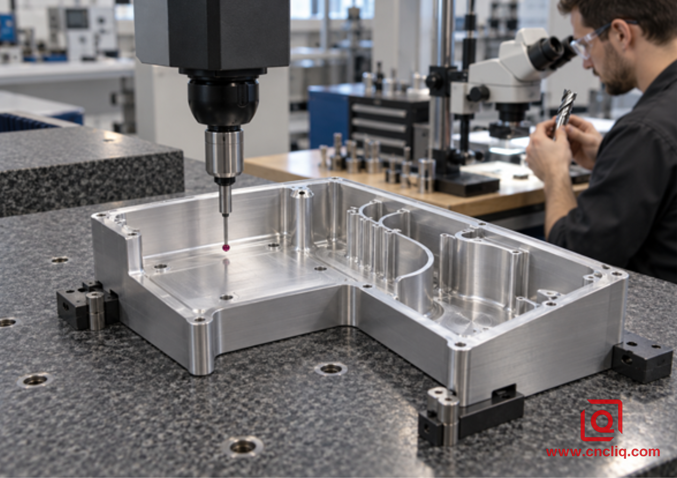
CMM inspection of a finished deep-pocket aluminum enclosure
Inspection proves whether the evacuation strategy protected the functional walls, floor, and datums.
The improvement was process stability: fewer manual interventions, cleaner finish passes, and evidence that the same chip route worked at maximum depth. No universal coolant pressure or headline cycle-time claim is assigned to this case because the correct values depend on the actual drawing, machine, tool, and fluid system.
For buyers comparing a similar project, the precision aluminum light housing demonstrates a related combination of an aluminum enclosure, CNC-machined sealing surfaces, threaded features, and inspection. It is a product reference, not a claim that the anonymous housing uses the same geometry or process.
10. DFM and RFQ Details That Reduce Evacuation Risk
For a useful deep pocket aluminum milling quotation, provide:
· a stable STEP model and controlled 2D drawing;
· exact aluminum alloy, temper, stock form, and required certificates;
· pocket depth, minimum width, internal radii, wall and floor thickness;
· critical datums, geometric tolerances, threads, and roughness zones;
· surface treatment, masking, and cosmetic requirements;
· prototype quantity, production quantity, and annual demand;
· cleanliness, leak, pressure, traceability, and packaging requirements;
· delivery target and revision status;
· any history of packed chips, broken tools, scratched floors, or distortion.
That information lets the supplier compare 3-axis, 3+2, full 5-axis, and horizontal machining on real process needs. It also separates evacuation risk from residual-stress and clamping risk. The custom aluminum OEM parts guide provides broader material and finishing context.
If your current cycle depends on repeated manual blow-outs, include that fact. A supplier should explain how it will validate the deepest engagement, control projection and runout, deliver coolant or air, clean hidden regions, and inspect the result. Liqin can review the model, pocket access, datum plan, finish allowance, and inspection scope before pricing. Send the drawing and quantity for a project-specific DFM review.
FAQs
1. Is through-spindle coolant always required for deep pocket aluminum milling?
No. Through-spindle or through-tool coolant can be valuable when the outlet reaches the active edge and carries chips toward a real exit. A stable external jet or qualified air/MQL system can work in an accessible pocket. The choice depends on pocket geometry, tool design, machine capability, alloy, production volume, enclosure, extraction, and fire controls. Validate delivery at maximum depth instead of selecting by pressure alone.
2. Is a 2-flute or 3-flute end mill better for deep aluminum pockets?
A 2-flute aluminum-specific cutter is often the safer starting point when flute space dominates, especially in a narrow slot or enclosed cavity. A 3-flute tool may improve feed potential and core stiffness when engagement is open and chip removal is already dependable. The edge, polish, runout, projection, radial engagement, and delivery path can outweigh flute count, so use the exact manufacturer's data.
3. Can I fix chip packing by reducing feed?
Not automatically. If RPM stays constant, lowering feed reduces real chip thickness and may make a sharp edge rub, raising heat and adhesion. First inspect trapped chips, nozzle reach, runout, tool wear, holder condition, stick-out, corner engagement, and machine motion. Then change 1 variable within the approved tool window and record the result.
4. Why is the pocket floor scratched even when dimensions are correct?
Loose roughing chips may remain on the floor and be dragged through the finish pass. A long tool can also deflect while recutting debris. Add a defined cleaning checkpoint before finishing, verify the edge, confirm uniform stock, and use a separate finish path. If the floor is functional, specify its roughness and inspection method so appearance is not the only acceptance criterion.
5. What should a buyer ask a supplier about chip evacuation?
Ask how the supplier maps the chip route, proves the deepest cut, controls tool projection and runout, checks nozzle reach, manages filtration and coolant condition, separates roughing from finishing, removes chips from intersecting passages, monitors tool wear, and documents inspection. A credible answer connects the drawing, machine, fixture, tool, CAM strategy, fluid system, and quality plan.
Summary
Reliable deep pocket aluminum milling begins with a deliberate chip exit. Create open volume with a rigid tool, preserve flute space, keep engagement predictable, deliver coolant or air to the actual cutting depth, break return-flow loops, use gravity when practical, and finish only after the cavity and edge are clean. Pair those controls with clear DFM, RFQ, and inspection requirements, and chip evacuation becomes a repeatable production variable instead of an operator rescue task.
Contact Information
Company: Ningbo Liqin Industry Co., Ltd.
Daily customer maintenance & after-sales support:service@shturl. zhuwanying@cncliq.com
New inquiry, quotation & order discussion:business@shturl. zhouli@chinaliqin.com
Hotline: +86 18757148656
Disclaimer
All technical articles, material specifications, machining recommendations, and surface treatment details published on this blog are for informational and reference purposes only. Please note that general blog insights do not replace signed technical agreements. Because custom parts vary by material heat numbers, machine calibrations, and specific tolerances, binding quality specs are governed solely by your approved CAD drawings, signed contracts, and formal quality plans.
All customer case studies featured on this blog have been thoroughly anonymized and sanitized. The performance metrics, manufacturing workflows, and imagery displayed serve solely to demonstrate our custom machining capabilities and do not represent a single universal standard for all orders.
Liqin Manufacturing Team
Built on 18 years of precision engineering experience, Ningbo Liqin Industry manufactures high-tolerance metal components for demanding global markets. We operate out of a 6,500 m2 production hub equipped with over 150 machines, running 4-axis and 5-axis CNC machining, mill-turn machining, cold extrusion, and pressure die casting under one roof. This setup allows us to manage projects seamlessly, taking parts from initial CAD concepts directly to finalized shipments.
We handle quality control with zero compromise. We treat tight tolerances with the engineering discipline they require. Backed by ISO 9001, ISO 13485, and IATF 16949 certifications, our QA engineers run strict IPQC, FQC, and OQC checks on every single production batch. From CMM dimensional mapping and optical profiling to hardness and salt-spray testing, we validate your critical specs upfront - so you receive drop-in ready components with zero assembly headaches or costly line stoppages. On top of manufacturing, you can rely on us for two-hour response times on new RFQs, direct support for prototype sampling, and smooth export shipping across Europe, North America, Asia, and Oceania.
Welcome your inquiries and samples. Visit our website or contact us directly for a competitive quote!
