 English




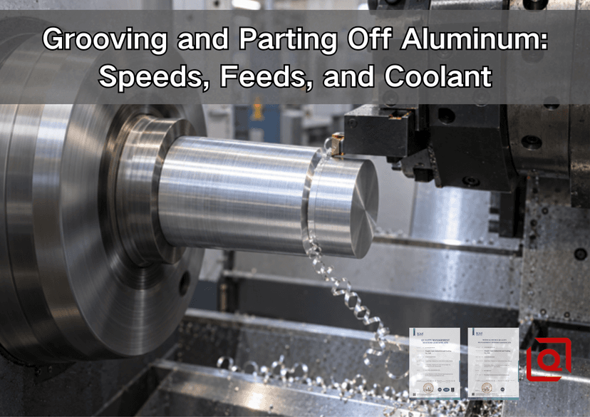
Are you still fighting a parting tool that squeals, welds aluminum to its edge, or leaves a stubborn pip? Read this shop-floor guide before changing another insert. The cut happens inside a narrowing channel where the blade can deflect and coolant can be blocked. A stable cycle treats speed, feed, blade width, center height, overhang, chip shape, and coolant delivery as 1 system.
The 30-Second Shop Answer
Use the narrowest rigid blade that meets the drawing, keep it square to the spindle axis, set the cutting edge on center, and minimize projection. Choose a sharp, polished, positive geometry intended for non-ferrous material. Program cutting speed as surface speed, not a remembered RPM; keep feed in mm/rev so chip thickness remains tied to each revolution. Aim a coherent coolant stream at the rake face and, for deep cuts, use a tool with internal coolant when the holder system supports it. Do not creep through the whole cut. A feed that is too timid can make aluminum rub, smear, and build an edge.
For a new aluminum part, prove the operation at a reduced but meaningful load while watching chip flow, spindle load, sound, and the groove walls. Increase toward the exact toolmaker's range only after the chip exits cleanly. Near final separation, follow the tool supplier's cutoff guidance; some systems call for a substantial feed reduction just before fall-off to lower the remaining core load. If the part transfers to a sub-spindle, coordinate clamp, speed, and cutoff position instead of letting a loose component drop unpredictably.
Why Aluminum Makes a Narrow Cut Unforgiving
Aluminum removes easily, but many grades are ductile enough to form long ribbon chips. In open turning those chips have room to curl away. Inside a 2 mm or 3 mm groove, the sidewalls fence them in. If the chip is wider than the channel or curls toward the wrong wall, it rubs twice: first on the insert, then on the newly cut surface. Heat and pressure encourage built-up edge, often shortened to BUE. The edge then behaves wider and blunter than the programmed tool, so cutting force rises and groove size or face finish moves.
The blade is also a slender cantilever. Every extra millimeter of projection increases its opportunity to twist. A tool mounted slightly off square cuts harder on 1 side. A cutting edge above or below center changes the effective geometry and can leave a pip, dish the cutoff face, or pull the blade sideways as the diameter collapses. These are setup errors, not problems that a faster spindle can automatically cure.
Alloy and stock form matter. Extruded 6061-T6 bar can behave differently from cold-finished bar, and a full material callout is better than the word “aluminum.” ASTM B221 covers aluminum-alloy extruded bar, rod, wire, profiles, and tube, while ASTM B211 covers rolled or cold-finished bar, rod, and wire. Liqin's aluminum CNC turning alloy guide discusses how common 6061, 7075, 2024, and 6082 choices affect chip behavior and downstream finishing.
Build the Setup Before Tuning the Numbers
1. Choose an aluminum-specific cutting edge
Start with the insert family, not a generic material chart. A polished rake face, sharp edge, positive geometry, and chipformer designed for non-ferrous work reduce the force needed to shear ductile aluminum. A steel-oriented edge with a heavy hone may be strong, but it can push and smear aluminum before it cuts. For production, record the exact insert, grade, chipformer, width, corner geometry, holder, and blade. “Carbide cutoff tool” is not enough to reproduce a proven process.
2. Use only the width and reach the feature needs
A wider insert consumes more material and makes more force; an unnecessarily narrow insert may lack stiffness or chipforming room. Balance material yield against reliability. Then set blade projection only deep enough to reach the target radius with safe clearance. Deep parting should use the matching reinforced blade and holder rather than a long, lightly clamped improvised stickout. Check that the holder seat is clean and that the insert is fully located.
3. Square the tool and verify center height
Sweep or indicate the blade against a known reference so its sides are perpendicular to the spindle axis. A visual check is not enough for a deep channel. Set the edge on center using the machine and holder manufacturer's method, then prove it on scrap. A persistent nub on solid stock, concave cutoff face, unequal side rub, or a tool that steers as it nears center is evidence to inspect center height and squareness before editing speed.
4. Control the workpiece and the separated part
Keep the cutoff close to the chuck or guide bushing while respecting jaw clearance. Long unsupported bar amplifies vibration. For small feature-dense shafts, guide-bushing support may make Swiss machining attractive; Liqin's comparison of Swiss machining and standard CNC turning shows why support location and backside work matter more than a simple diameter rule. On a sub-spindle machine, specify whether the secondary spindle grips before cutoff and which face becomes the finished datum.
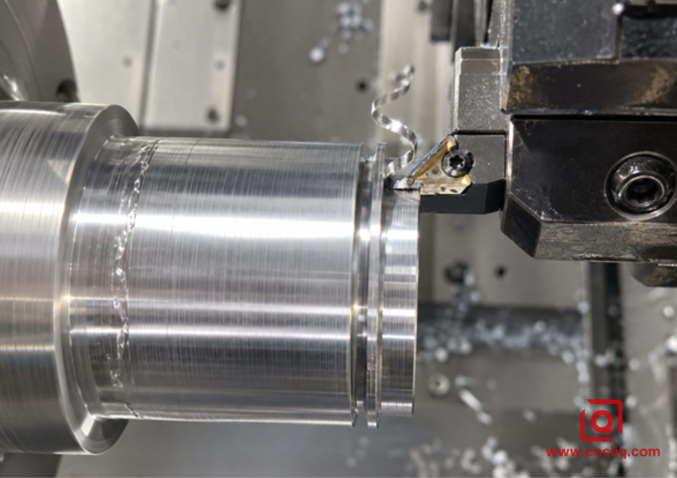
A short, square, aluminum-specific grooving setup gives the process its widest stability window.
Speeds and Feeds: Calculate First, Then Prove the Cut
Cutting speed Vc describes surface speed at the cutting diameter. In metric units, spindle speed n is calculated as n = (1,000 × Vc) ÷ (π × D), where Vc is in m/min, D is diameter in mm, and n is RPM. Feed rate in mm/min is n × f, where f is feed in mm/rev. On a lathe program, mm/rev is usually the more useful control for grooving because it preserves feed per revolution as RPM changes.
Example: assume the selected insert sheet permits a 300 m/min trial for the exact aluminum alloy and operation. At 50 mm diameter, the calculated speed is about 1,910 RPM. At 20 mm diameter, maintaining 300 m/min would require about 4,775 RPM. That rise explains the purpose of constant surface speed, or CSS. The controller increases RPM as the tool moves inward, subject to a programmed maximum. Set that maximum before the cut; chucking, bar balance, workholding, spindle rating, and the receiving method decide the safe ceiling.
If the machine reaches the RPM cap, surface speed falls through the rest of the plunge. That is normal. The operator needs to know where it happens because a sticky aluminum grade may become more prone to BUE in the low-speed center region. Do not remove the cap to make the formula look perfect. Use the correct edge, firm feed, effective lubrication, and a controlled final-core strategy.
Feed cannot be separated from width and geometry. A 1.5 mm insert, a 3 mm insert, and a form tool do not carry the same chip or force. Deeper cuts also reduce the room available for a curled chip. Use the feed band printed for the exact insert, then derate only for a stated reason such as weak workholding, long reach, interrupted entry, thin-wall distortion, or a machine load limit. Randomly halving feed can make the edge rub instead of solving the original problem.
|
Input or condition |
Practical starting decision |
Why it matters |
|
Cutting speed Vc |
Use the exact insert maker range for aluminum and the operation |
Coating, edge preparation, alloy, and groove depth change the valid range |
|
Feed f |
Choose mm/rev from the insert-width table |
Chipformer performance and cutting force depend on real chip thickness |
|
RPM mode |
CSS with a safe maximum where the machine and workholding allow |
Diameter falls continuously during a radial plunge |
|
Groove depth |
Apply the supplier depth correction or staged strategy |
Chip evacuation and blade stability worsen as the channel closes |
|
Final core |
Follow the cutoff system guidance; often reduce feed close to separation |
Limits the last-core load and helps control the separated part |
|
Coolant |
Coherent jet at the edge; internal delivery for difficult deep cuts |
Cools, lubricates, and carries chips out before they recut |
A useful published reference—and why it is not a universal recipe
ThinBIT publishes 1,000 SFM and 0.002 IPR for 1 DURA-MAX 5000 carbide grooving family in aluminum grades 2021–6061. Converted, that is about 305 m/min and 0.051 mm/rev. This is valuable because it is tied to a named tool family, not because every carbide cutoff insert should run there. A different width, chipformer, grade, reach, coolant path, or alloy can require different data. Use the number to check order of magnitude, then open the application sheet for the tool actually in the turret.
The same discipline applies to 6061 more broadly. Liqin's 6061 feeds, speeds, and tooling guide explains the difference between a calculated starting point and a validated production setting. That article covers milling as well as general tooling; this guide narrows the problem to radial lathe cuts, where diameter changes continuously and the channel traps the chip.
Coolant: Placement Matters More Than a Flooded Window
A large volume of coolant hitting the holder does not prove that fluid reaches the edge. The channel itself blocks access as the blade moves deeper. Coolant has 3 jobs here: reduce friction on the rake and side faces, carry heat away, and push the chip out of a slot that is closing around it. Put the nozzle where its stream remains coherent at cutting depth. Check it at a safe standstill with the actual tool position, not only with the turret at home.
Sandvik Coromant's technical paper on coolant in parting and grooving explains why precision delivery at the cutting zone is more effective than conventional external flooding. Its parting guidance also notes a larger high-pressure-coolant effect in smearing materials such as aluminum, where chip control is difficult. Internal-coolant blades can send fluid above and below the insert, but pressure alone is not the specification. The holder, seals, filtration, concentration, nozzle geometry, and machine pump must work as a rated system.
Use a fluid approved for aluminum and the machine, maintained to the supplier's concentration and water-quality guidance. Record any refractometer correction factor. A generic percentage copied from another shop is not a quality plan, and an improvised flammable liquid does not belong inside an enclosed machine.
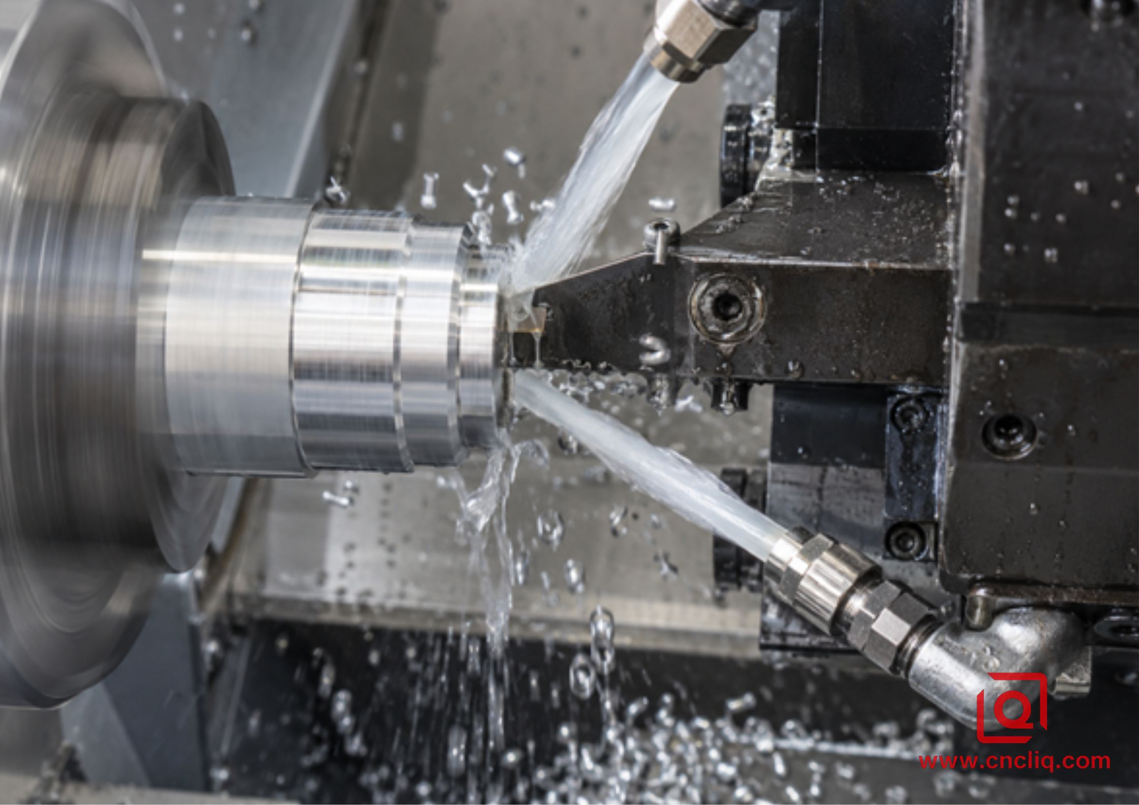
Coherent coolant delivery above and below the blade reaches the cutting zone and helps evacuate ductile aluminum chips.
Troubleshooting Aluminum Grooving and Parting
|
Symptom |
Likely mechanism |
First checks |
Corrective direction |
|
High-pitched chatter |
Long projection, weak support, blade off square, speed exciting the system |
Projection, chuck distance, holder seat, center height |
Shorten and stiffen before changing parameters; then adjust within tool data |
|
Aluminum welded to edge |
Rubbing, weak lubrication, damaged edge, low effective speed near center |
Feed mode, RPM cap, coolant aim, insert geometry |
Restore a real chip, replace damaged insert, improve edge lubrication |
|
Chip jam or bird nest |
Chip too wide or long for groove; poor evacuation |
Chipformer, feed, alloy, depth, coolant direction |
Use approved feed and geometry; improve delivery; controlled peck only if recommended |
|
Groove wider at mouth |
Blade deflection or side rubbing |
Squareness, projection, tool seat, chip wedging |
Correct alignment and rigidity; avoid burying both sides during widening |
|
Pip or dished cutoff face |
Center-height error, deflection, final-core overload |
Edge height, blade square, receiving method |
Reset tool and apply the supplier's final-core strategy |
|
Burr on 1 wall |
Side bias, worn corner, axial pull |
Insert condition, alignment, path direction |
Replace edge, square tool, revise final wall pass |
|
Random scratches |
Recut chips trapped between wall and blade |
Chip exit path, coolant, retract sequence |
Flush chips away and avoid dragging them during retract |
Do not change 4 variables at once. If a trial chatters, first restore known mechanical conditions, then change 1 parameter within the approved band and record the result. A production process should be auditable: tool life by parts or cutting time, rejection reason, insert failure mode, coolant check, dimensional trend, and any offset intervention. That record is more valuable than a single “perfect” first part.
Anonymous Composite Case: 6082-T6 Fluid-Control Spool
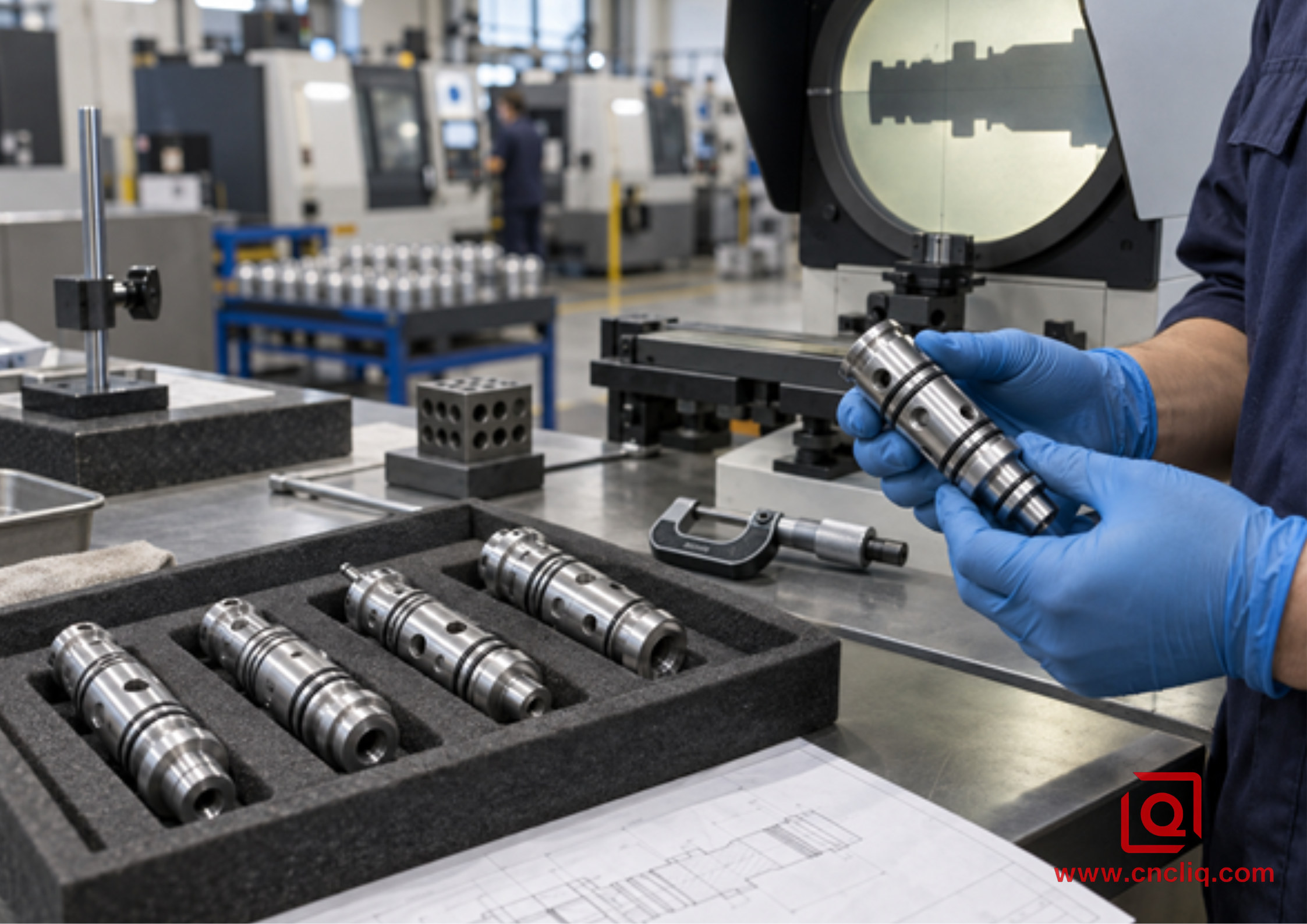
An anonymized representative part family: turned aluminum spools with multiple sealing grooves, cross-holes, and controlled inspection.
An anonymized composite buyer needed a family of compact 6082-T6 fluid-control spools for industrial automation equipment. The geometry was consistent with Liqin's published custom aluminum machining capability: a turned body, several O-ring grooves, cross-drilled ports, a central bore, and a separated rear face that would be back-worked.
The first trial used 1 general-purpose 3 mm cutoff insert for the sealing grooves and final separation. The grooves measured acceptably near the mouth, but witness marks appeared on 1 wall as depth increased. A long ribbon chip repeatedly climbed over the blade. Near cutoff, the separated blank occasionally left a heavy pip, adding manual rework and making the rear-face allowance inconsistent.
The process team separated the jobs. A narrower polished positive-rake grooving insert produced the sealing features with a short projection. Groove width was generated by a controlled plunge-and-wall-finishing sequence rather than burying both insert corners. A dedicated reinforced cutoff blade handled separation. The holder's internal coolant path aimed at the rake face, while the sub-spindle gripped the part before the final core was cut. Tool geometry, feed range, and final-core reduction followed the selected supplier's application sheet.
First-piece inspection covered groove width, bottom diameter, axial location, corner condition, and burr. A profile projector checked groove form; micrometers and a CMM checked accessible diameters and port relationships. Surface finish was specified only on functional sealing areas.
The transferable lesson was not a dramatic speed increase. Reliability came from matching 1 tool to sealing grooves and another to separation, shortening the blade, controlling the chip, and defining which face the sub-spindle owned. Buyers can apply the same logic when sourcing a custom hydraulic manifold or valve component: send the complete functional drawing and assembly context, not an isolated STEP file with “make to model.”
Design and RFQ Details That Prevent Costly Assumptions
A supplier cannot quote groove performance from a rendered image. Send the native 3D model and a controlled 2D drawing. State alloy, temper, and stock form; prototype quantity and annual demand; critical datums; groove width, diameter, corner radii, and surface finish only where functional; burr and edge-break expectations; anodizing or other finish; inspection documents; packing; and delivery target. For cutoff, say whether the separated face is final, faced later, or transferred to a sub-spindle.
If the component combines concentric bores, O-ring grooves, cross-holes, flats, and backside features, ask the supplier to state the proposed process route. Liqin's guide to CNC turning versus turn-mill machining for concentric aluminum housings explains how datum continuity and process consolidation affect more than cycle time. The cheapest-looking quote can become expensive when an unplanned second setup adds runout, deburring, inspection, or handling.
Planning a custom aluminum shaft, spool, sleeve, fitting, or housing? Send your STEP file, 2D drawing, alloy and temper, quantities, critical groove callouts, finish, and delivery target. Liqin can review tool access, process routing, datum control, inspection needs, and manufacturability before quotation. Request a DFM review and competitive quote.
FAQ
1. What is a safe starting speed and feed for parting 6061 aluminum?
There is no responsible universal setting because insert width, grade, chipformer, depth, coolant, machine rigidity, and bar diameter change the result. Use the exact insert maker's aluminum data. As a scale check only, 1 published ThinBIT carbide family lists about 305 m/min and 0.051 mm/rev for 2021–6061 aluminum. Calculate RPM from the current diameter, apply a safe maximum, prove the cut under supervision, and adjust 1 variable at a time.
2. Should I use constant surface speed for aluminum parting?
CSS is useful because cutting diameter falls throughout the plunge, but it must always have a safe RPM cap based on the spindle, workholding, bar balance, chucking, tool, and part-catching method. When the cap is reached, surface speed will fall toward center. That is preferable to exceeding a safe rotational limit. Keep feed in mm/rev and use the edge, chipformer, coolant, and final-core method recommended for the selected system.
3. Why does aluminum weld to the parting insert even with coolant?
The fluid may be striking the holder instead of the edge, or the insert may be rubbing because feed is too light, the edge is worn, surface speed has fallen, or the geometry is not intended for non-ferrous material. Check center height, squareness, projection, feed mode, RPM cap, chip shape, and nozzle aim. Once aluminum has built onto the edge, replace or service the insert as permitted after correcting the cause; continuing often damages the groove wall.
4. Is peck parting better than a continuous feed?
Not automatically. A controlled peck can help when a ductile ribbon chip will not clear, but repeated exits and re-entries can rub the walls, shock the edge, and trap a loose chip. First use the correct chipformer, approved feed, short rigid setup, and effective coolant. If the toolmaker recommends pecking for the depth and alloy, follow that specific sequence and inspect whether it creates manageable chips rather than a larger bird nest.
5. What information does Liqin need to quote grooved aluminum parts?
Provide a STEP model and controlled 2D drawing, full alloy and temper, quantity, critical datums and tolerances, groove width and bottom diameter, corner radii, surface-finish locations, burr limits, cutoff-face allowance, anodizing or coating, inspection records, and delivery target. Also identify cross-holes, thin walls, sub-spindle pickup surfaces, cosmetic zones, and any prior chip, chatter, leakage, or tool-life issue. This lets the process engineer quote the route rather than guess from geometry.
Summary
Reliable aluminum grooving and parting begins with a short, square, on-center blade and a sharp non-ferrous insert, then combines tool-specific surface speed, real feed per revolution, a safe CSS limit, controlled final separation, and coolant that reaches the edge. Read chips, sound, load, tool condition, and measured features together. For B2B sourcing, define the functional groove, cutoff-face routing, material condition, finish stage, and inspection plan so the quotation reflects a repeatable manufacturing process rather than a hopeful first cut.
Contact Information
Company: Ningbo Liqin Industry Co., Ltd.
Daily customer maintenance & after-sales support:service@shturl. zhuwanying@cncliq.com
New inquiry, quotation & order discussion:business@shturl. zhouli@chinaliqin.com
Hotline: +86 18757148656
Disclaimer
All technical articles, material specifications, machining recommendations, and surface treatment details published on this blog are for informational and reference purposes only. Please note that general blog insights do not replace signed technical agreements. Because custom parts vary by material heat numbers, machine calibrations, and specific tolerances, binding quality specs are governed solely by your approved CAD drawings, signed contracts, and formal quality plans.
All customer case studies featured on this blog have been thoroughly anonymized and sanitized. The performance metrics, manufacturing workflows, and imagery displayed serve solely to demonstrate our custom machining capabilities and do not represent a single universal standard for all orders.
Liqin Manufacturing Team
Built on 18 years of precision engineering experience, Ningbo Liqin Industry manufactures high-tolerance metal components for demanding global markets. We operate out of a 6,500 m² production hub equipped with over 150 machines, running 4-axis and 5-axis CNC machining, mill-turn machining, cold extrusion, and pressure die casting under one roof. This setup allows us to manage projects seamlessly, taking parts from initial CAD concepts directly to finalized shipments.
We handle quality control with zero compromise. We treat tight tolerances with the engineering discipline they require. Backed by ISO 9001, ISO 13485, and IATF 16949 certifications, our QA engineers run strict IPQC, FQC, and OQC checks on every single production batch. From CMM dimensional mapping and optical profiling to hardness and salt-spray testing, we validate your critical specs upfront—so you receive drop-in ready components with zero assembly headaches or costly line stoppages. On top of manufacturing, you can rely on us for two-hour response times on new RFQs, direct support for prototype sampling, and smooth export shipping across Europe, North America, Asia, and Oceania.
Welcome your inquiries and samples. Visit our website or contact us directly for a competitive quote!
