 English





Have you ever pulled a 2024 aluminum job from the vise and watched a “good” dimension disappear? Maybe the wall opened up. Maybe the finish went gray halfway through the lot. This guide is for the person who has to explain that result, fix it, and quote the next batch with a straight face. We will work from the spindle outward: temper, edge geometry, chip thickness, engagement, coolant, then inspection. The aim is fewer unknowns on the quote and fewer uncomfortable surprises at final inspection.
Calling 2024 “just another easy aluminum” is where trouble starts. A clean first piece can turn into a hazy wall after the edge collects a thin aluminum skin. Add spindle heat and released stock stress, and a small drift becomes a batch problem.
Fast answer: For a rigid CNC mill using a sharp two- or three-flute carbide end mill, a practical trial window for wrought 2024 is often 245–455 m/min (800–1,500 SFM), then adjusted for tool diameter, engagement, holder, machine power, and coolant delivery. Set feed from chip load, not from a comfortable-looking feed-rate number. Treat every table below as a controlled starting point and give the tool manufacturer’s current data priority.
1. What Makes 2024 Different at the Spindle
On a mill certificate, 2024 appears as a heat-treatable Al-Cu-Mg alloy. Expect copper at 3.8–4.9%, magnesium at 1.2–1.8%, and manganese at 0.3–0.9%. Density is roughly 2.78 g/cm³ and elastic modulus about 73.1 GPa. NIST’s Properties of Wrought Aluminum and Aluminum Alloys lists 485 MPa ultimate and 345 MPa yield strength as typical for bare T3; T4/T351 is about 470 MPa ultimate and 325 MPa yield. Those are reference values, not drawing values. Product form, thickness, orientation, and the governing specification still decide what the supplier must certify.
At the spindle, a long tool can be pushed off the wall while the matrix smears onto a poorly lubricated edge. Copper-rich particles continue wearing the flank. Inspect every flute; one deposit or narrow wear land can already steer size and finish.
Temper matters just as much as alloy designation. T3 sheet and T351 plate are not interchangeable process inputs. T351 has been stress-relieved by stretching and is usually the safer starting form for a deep-pocketed plate component, but it is not stress-free. Remove most of the section from one side and the remaining stress field can still bend the part. Before quoting, record the full callout—2024-T3, T351, T851, Alclad or bare—plus product form and material standard.
|
Item |
Shop-floor meaning |
RFQ detail to confirm |
|
2024-T3 |
High strength; residual stress can become visible after heavy or uneven removal |
Sheet/bar form, thickness, grain direction, bare or clad |
|
2024-T351 |
Stretch stress-relief improves plate stability, but asymmetric pocketing can still release stress |
Plate certification, cut orientation, flatness allowance |
|
2024-T851 |
Higher-strength artificially aged condition; cutting data and finish plan need their own trial |
Exact product form and mechanical-property requirement |
|
Alclad 2024 |
Thin corrosion-resistant cladding can be removed or damaged by machining |
Areas where cladding must remain and edge-protection requirement
|
Need an alloy comparison first? Our guide to CNC milling 6061, 7075, and 5052 aluminum sets the baseline. Bring three extra questions back to a 2024 print: which faces see cyclic stress, where will stock stress escape, and what edge condition ends the tool’s approved life?
2. Build the Starting Parameters Instead of Guessing
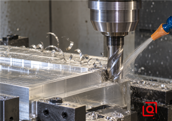
Carbide end milling of 2024 aluminum: evaluate cutting speed and chip load together.
Three equations keep the setup honest:
Spindle speed: n = (1,000 × Vc) / (π × D)
Table feed: Vf = n × z × fz
Material removal rate: Q = ap × ae × Vf / 1,000
Here, Vc is cutting speed in m/min, D is tool diameter in mm, n is rpm, z is flute count, fz is feed per tooth in mm/tooth, ap is axial depth in mm, ae is radial engagement in mm, and Q is cm³/min. These formulas do not select a safe toolpath. They only translate a chosen cutting condition into machine commands.
Take a 12 mm, three-flute carbide cutter as a quick check. A 300 m/min surface speed works out to about 7,960 rpm; 0.08 mm per tooth then gives roughly 1,910 mm/min. I would try that on a rigid side cut, not blindly paste it into every operation. A full slot, 60 mm of stick-out, a thin rib, or a slow control negotiating tiny arcs changes the answer.
Harvey Performance recommends 800–1,500 SFM as a starting surface-speed band for wrought aluminum alloys including 2024, 6061, and 7075, while stressing flute space and chip evacuation. Kennametal’s troubleshooting guidance adds a practical correction: built-up edge often calls for a sharper positive edge, more effective coolant, and—within the tool’s approved window—higher speed or chip thickness; rapid flank wear or heat damage often calls for lower cutting speed. These are directional rules, not permission to change several variables at once.
Starting windows for carbide end milling 2024
|
Operation |
Vc, m/min (SFM) |
fz for Ø6–12 mm tool, mm/tooth |
ap |
ae |
First risk to watch |
|
Full-width slot |
245–335 (800–1,100) |
0.03–0.07 |
0.25–0.75 × D |
1.00 × D |
Chip packing and flute welding |
|
Conventional pocket roughing |
275–395 (900–1,300) |
0.04–0.09 |
0.5–1.0 × D |
0.25–0.50 × D |
Load spikes in corners |
|
Dynamic/adaptive roughing |
305–455 (1,000–1,500) |
0.05–0.11 |
1.0–2.0 × D |
0.08–0.20 × D |
Chip thinning and tool runout |
|
Finish wall pass |
335–455 (1,100–1,500) |
0.02–0.06 |
Up to 1.5 × D |
0.02–0.08 × D |
Deflection, waviness, BUE |
|
Finish floor pass |
305–425 (1,000–1,400) |
0.03–0.07 |
0.1–0.3 mm |
0.40–0.70 × D |
Chip recutting and witness marks
|
These broad bands are starting territory. Stay toward the lower-middle when the setup flexes, projection exceeds about 3×D, or coolant access is poor. A rigid, balanced system may support more; a light router may need far less engagement despite having the rpm.
Do not “solve” a noisy cut by reducing feed alone. If rpm stays fixed, that move makes the chip thinner. The edge begins rubbing, temperature rises, and aluminum can smear onto the flute. When chatter appears, first check runout, stick-out, holder condition, fixture contact, and corner engagement. Then alter one variable and record the result.
3. Tool Geometry: Give the Chip Somewhere to Go
For general roughing with a solid carbide end mill, two or three flutes are the normal starting point. Two flutes provide generous chip space for slots and weak coolant delivery. Three flutes can raise productivity and often finish well when the machine and evacuation system can keep up. Four flutes may work in light finishing, but using a steel-style multi-flute cutter in a deep 2024 pocket leaves less gullet volume exactly where chip load is high.
Choose a tool made for aluminum: sharp cutting edge, high positive rake, polished flute, and open geometry. A high helix can reduce radial force and pull chips out of a pocket, although it also increases axial pull and demands secure tool holding. Minimize runout; if one flute carries most of the chip load, the average feed calculation is misleading and that flute will wear first.
For an unfamiliar job, polished uncoated carbide is a sound baseline. ZrN or DLC may help when adhesion repeats, while PCD suits stable, high-volume finishing. A steel cutter’s coating and edge hone may resist heat well yet shear aluminum poorly.
For multi-face parts with deep pockets or compound access, tool selection cannot be separated from setup count. The guide to multi-axis CNC milling for complex aluminum geometries explains why shorter tools and fewer re-clamps can improve datum control as well as cycle time.
4. Engagement Rules for Roughing, Walls, Slots, and Holes
Dynamic roughing
Adaptive or trochoidal paths keep engagement more constant than a conventional pocket routine. Use low radial engagement and deeper axial engagement so wear is distributed along more flute length. Program a smooth helical or ramp entry rather than a straight plunge unless the cutter is designed to center-cut. Verify actual chip thinning: at small ae, programmed fz may need correction to produce the intended maximum chip thickness.
Slotting
A slot is a different operation, not merely a pocket at the same settings. The cutter is engaged on both sides, chip space is restricted, and recutting risk climbs. Reduce speed or depth according to the tool maker’s data, maintain chip load, and improve air/coolant direction. If a deep slot must be made, divide it into controlled axial steps or use a narrower tool and open the slot with side engagement.
Thin walls and floors
Rough both sides while the structure is still stiff, leave balanced stock, and finish in staged passes. A long wall often responds better to several axial bands than one full-height skim. Alternate the cutting direction or sequence to avoid pushing repeatedly toward the weak side. For a thin floor, support it where possible, reduce axial force, and use a toolpath that does not trap hot chips under the cutter.
Drilling, reaming, and threads
Deep drilling becomes a chip-storage problem. Use through-tool coolant where suitable, and peck only as the drill supplier directs. A reamer will follow a wandering pilot hole, so correct the drill first. On an expensive blank, thread milling reduces the risk of a buried broken tap. If tapping wins on volume, control the pre-hole, synchronization, lubricant, and chip exit together; inspect the first threads before trusting the torque alarm.
5. Coolant and Chip Evacuation: Aim Matters More Than Noise
2024 conducts heat well, so much of the heat leaves with the chip—if the chip leaves. A large flood that misses the cutting zone can be less useful than a smaller, stable jet aimed into the flute exit. Deep cavities need a route for chips to escape. Through-tool coolant, well-placed nozzles, or a strong air/oil mist may be appropriate depending on machine design, fire controls, local rules, and part geometry.
Maintain coolant concentration within the fluid supplier’s specified band and verify it with a refractometer. A weak or contaminated mix reduces lubricity and can stain the work. An overly rich mix adds cost and may create residue or operator exposure issues. Record concentration, sump condition, and temperature with tool-life data; otherwise a “tool problem” may actually be a coolant shift.
Watch the chips. Bright, separated curls or commas are generally healthier than flattened, welded, dark, or repeatedly crushed chips. A nest around the holder means evacuation has already failed. Stop and correct it before the nest drags across the surface or blocks coolant.
6. Read Tool Wear Before the Part Reports It
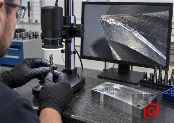
Inspect each flute at fixed intervals to separate built-up edge, flank wear, and micro-chipping.
Tool wear should be classified, not described as “the cutter went bad.” Use a loupe or microscope and compare the same flute locations at a fixed interval.
|
Symptom |
Likely mechanism |
Confirm before changing data |
Controlled response |
|
Aluminum stuck to rake face; smeared finish |
Built-up edge (BUE) |
Coolant aim, speed, actual chip thickness, polished edge |
Clean/replace edge; restore lubrication; raise speed or chip thickness only within tool limits |
|
Even shiny land behind edge |
Flank wear |
Cutting time, Vc, abrasive contact, runout |
Reduce Vc; use a more wear-resistant grade/coating; set a wear limit |
|
Small broken sections on one flute |
Micro-chipping or overload |
Runout, interrupted entry, chip recutting, holder rigidity |
Correct runout/entry; reduce peak engagement or fz; improve evacuation |
|
Repeating bands on wall |
Runout, chatter, worn edge or deflection |
Tool projection, spindle/holder, wall support |
Shorten assembly; balance stock; use a light isolated finish pass |
|
Diameter grows during batch |
Edge wear or thermal drift |
Tool offsets, spindle/coolant temperature, gauge trend |
Separate wear compensation from thermal compensation; change tool by trend |
|
Sudden load spike in corners |
Excess engagement or packed chips |
CAM simulation, corner radius, nozzle access |
Add smoothing/arc moves; lower ae; clear chips
|
Kennametal identifies uniform flank wear as the preferred predictable failure mode. That is a useful production target: predictable wear can be trended; random chipping cannot. Establish a tool-change rule tied to the critical feature—surface finish, bore size, wall profile, spindle-load change, or measured flank wear. A generic 0.30 mm VB limit may be far too late for a fatigue-sensitive surface or a ±0.01 mm feature.
Measure at a consistent interval. For a new process, inspect after the first part, then after a short controlled run. Record machining minutes, material lot, tool lot, offset changes, measured feature, roughness if specified, and a photo of the edge. Once the curve is stable, set a conservative scheduled change before the quality trend turns. If the cut changes abruptly, quarantine the last confirmed-good interval rather than guessing where failure began.
7. A Practical Dial-In Procedure
1. Lock the inputs. Confirm temper, stock form, hardness/certification requirement, tool part number, holder, projection, coolant, fixture, and CAM strategy.
2. Check the system before cutting. Measure runout near the cutting edge, inspect holder and spindle taper, and verify that the part sits on clean, repeatable datums.
3. Choose a conservative Vc and correct fz. Do not halve feed without understanding chip thickness. Keep a real chip under the edge.
4. Prove the worst engagement. Test the deepest corner, full slot, entry move, and longest unsupported wall—not only the easy straight cut.
5. Change one variable at a time. A 10–15% step is usually easier to interpret than a dramatic reset. Note sound, spindle load, chip form, edge condition, and measured result.
6. Separate roughing and finishing tools when risk justifies it. A rougher can lose a small edge and still remove stock; that same edge may fail a finish requirement.
7. Release the part before final acceptance. Unclamp, allow temperature to normalize, clean datums, and remeasure. This exposes clamp distortion and stress movement.
8. Freeze the proven window. Store the tool assembly, CAM revision, offsets, coolant condition, inspection frequency, and change criterion in the traveler.
This discipline is also useful when comparing milling, turning, and extrusion routes. The broader aluminum machining process guide helps place individual parameters inside the full manufacturing route.
8.Dimensional Stability: Cutting Data Cannot Fix a Bad Sequence
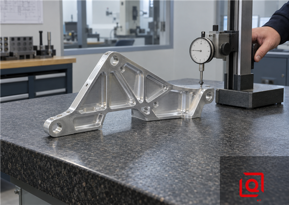
Measure released 2024-T351 parts after temperature stabilization; clamping can hide distortion.
Thermal movement is easy to underestimate. Use 23.2 µm/m·°C as a working expansion figure for 2024 between 20 and 100°C. On a 300 mm span, only 5°C of difference is worth roughly 0.035 mm—already more than plenty of drawing callouts. Write down part, room, and coolant temperature with the measurement. A hot machine result and a 20°C CMM result are not the same observation.
Residual stress is the other mover. When the specification allows T351 plate, keep blank orientation consistent and take comparable amounts from opposing faces. Our usual logic is rough, loosen the part, let it move, establish the datum again, and only then semi-finish and finish. The clamp should locate the work, not iron it flat. A dimension that changes after release points to sequence or workholding; another wear offset will only hide it for one setup.
Design choices can reduce the fight. Avoid an abrupt transition from a heavy boss to a paper-thin floor, give internal corners a machinable radius, identify true functional datums, and apply tight tolerances only where assembly requires them. For deeper DFM detail, see aluminum CNC milling material, tolerance, and design guidance.
9. Verified Product Example—and the Material Boundary
Liqin’s published precision aluminum manifold machining page shows the sort of geometry that makes process planning matter: crossed passages, threads, sealing faces, and several datums. The material line on that page starts with 6082-T6 and also offers 6061-T6 or 7075-T6. You will not find 2024 in that list. That distinction stays in this article; a useful example is not a license to change its alloy.
The process lesson is still relevant. For an anonymized fluid-control customer, the product geometry requires roughing with finish stock, re-established datums, multi-face machining, controlled drilling and threading, deburring of internal intersections, cleaning, and dimensional verification. If a new drawing calls for 2024, Liqin’s engineering team would need to revalidate raw-material certification, corrosion protection, cutting data, distortion control, pressure-related requirements, and inspection—not simply substitute the alloy in an existing program. That is the correct way to use a real product as a manufacturing case without inventing an order history or claiming unverified performance.
More published examples sit in the aluminum product category. Use them to judge the type of work, then send the real 2024 drawing; alloy, geometry, quantity, and inspection needs must be assessed together.
10. Before You Ask for a Quote: What We Actually Need
A STEP file gives the shape, not the whole risk. Pair it with a revision-controlled 2D drawing. State alloy, temper, stock form, governing specification, quantity, CTQ features, datums and GD&T, roughness, finish, inspection needs, documentation, packaging, and delivery date. Missing items become quote assumptions; visible items become a process plan.
Mark cyclic-load faces, bearing seats, seals, thin sections, and post-coating dimensions. If a tolerance is hard to classify, tell us what the feature does in the assembly. That note may suggest a better datum or inspection method.
For a DFM review and quotation, send your drawing through the Liqin contact page. Ask the team to return the proposed stock temper, toolpath approach, finish allowance, critical inspection plan, and any assumptions with the quote. A two-way technical review before cutting is cheaper than revising a batch after inspection.
FAQs
1. Does 2024 really cut harder than 6061 on the shop floor?
The first few chips may look so clean that 2024 seems no harder at all. The differences arrive later—in edge load, wear, corrosion planning, and movement after release. A good 6061 program is still useful, but only as a yardstick. Go back to the cutter sheet and prove the first run in 2024 before calling the route stable.
2. Where should I begin with cutting speed on a 2024 milling job?
Think of 245–455 m/min (800–1,500 SFM) as the outside fence, not the answer. Cutter diameter and reach, radial contact, holder, spindle, coolant, and the life target all move the starting point. Full slots and springy setups belong near the slow side. Light, stable engagement may justify more. Do the rpm math with the real diameter and keep the latest cutter sheet beside the program.
3. A brand-new tool is picking up aluminum—what went wrong?
A new cutter can weld aluminum almost at once if the cut makes heat instead of a chip. Check whether the edge is sharp and polished, whether runout leaves one flute doing the work, and whether the chip actually exits the pocket. Then look at speed, real chip thickness, and lubricant direction. After one change, stop and look at the edge again. Do not automatically reach for the feed override. A skinny chip that rubs can build the deposit faster, not cure it.
4. For a deep-pocket plate, is T351 the safer call than T3?
For a heavily pocketed plate, T351 is usually the calmer starting stock because it has been stretch stress-relieved. “Calmer” does not mean flat by itself. Keep track of grain and blank orientation, balance removal, release the clamps between stages, control heat, and inspect after the part relaxes. The shop should never make that substitution quietly. T3, T351, and another product form are drawing decisions; the design owner has to approve the change.
5. What shop signal should trigger a tool change in 2024?
Let the feature set the limit. A roughing tool can sometimes run with a visible, steady wear land; the finishing tool on a fatigue face or bearing bore may need to leave much earlier. During qualification, log cutting minutes beside size, roughness, spindle load, offsets, and measured VB. Choose the change point while those trends are still boring and predictable—not after the first chipped edge.
Summary
Good 2024 work is rarely saved by one clever setting. The stock temper, edge, tool contact, coolant path, fixture, and inspection timing have to agree. Keep a real chip under a sharp aluminum cutter, give that chip an exit, and name the wear you see. Balance heavy stock removal, let the part relax, then measure it at a known temperature. For a useful quotation, send the drawing set, material callout, volume, finish, and CTQ notes; that gives engineering something firmer than a generic cycle guess.
Contact Information
Company: Ningbo Liqin Industry Co., Ltd.
Daily customer maintenance & after-sales support:service@shturl. zhuwanying@cncliq.com
New inquiry, quotation & order discussion:business@shturl. zhouli@chinaliqin.com
Hotline: +86 18757148656
Disclaimer
All technical articles, material specifications, machining recommendations, and surface treatment details published on this blog are for informational and reference purposes only. Please note that general blog insights do not replace signed technical agreements. Because custom parts vary by material heat numbers, machine calibrations, and specific tolerances, binding quality specs are governed solely by your approved CAD drawings, signed contracts, and formal quality plans.
All customer case studies featured on this blog have been thoroughly anonymized and sanitized. The performance metrics, manufacturing workflows, and imagery displayed serve solely to demonstrate our custom machining capabilities and do not represent a single universal standard for all orders.
Liqin Manufacturing Team
Built on 18 years of precision engineering experience, Ningbo Liqin Industry manufactures high-tolerance metal components for demanding global markets. We operate out of a 6,500 m² production hub equipped with over 150 machines, running 4-axis and 5-axis CNC machining, mill-turn machining, cold extrusion, and pressure die casting under one roof. This setup allows us to manage projects seamlessly, taking parts from initial CAD concepts directly to finalized shipments.
We handle quality control with zero compromise. We treat tight tolerances with the engineering discipline they require. Backed by ISO 9001, ISO 13485, and IATF 16949 certifications, our QA engineers run strict IPQC, FQC, and OQC checks on every single production batch. From CMM dimensional mapping and optical profiling to hardness and salt-spray testing, we validate your critical specs upfront—so you receive drop-in ready components with zero assembly headaches or costly line stoppages. On top of manufacturing, you can rely on us for two-hour response times on new RFQs, direct support for prototype sampling, and smooth export shipping across Europe, North America, Asia, and Oceania.
Welcome your inquiries and samples. Visit our website or contact us directly for a competitive quote!
