 English




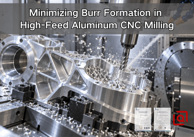
Are feather burrs, rolled exit edges, or hand deburring still eating up time after a milling cycle that looked fine through the window? Open the door and inspect the edge before anyone reaches for a brush. This guide follows the checks a machinist can actually use during prove-out, while also showing buyers what a supplier needs to quote a dependable high-feed aluminum process.
A burr tells a story. At the last instant of the cut, the remaining metal bent, rolled, or smeared instead of shearing away. Sometimes the culprit is a tired edge; on another job it is the exit direction or a thin wall moving under load. Alloy, chip thickness, runout, coolant aim, and fixture stiffness all join in. Push feed without sorting out that chain and the cycle clock improves while the accepted-part cost quietly moves the other way.
The Shop-Floor Answer, Before the Spindle Starts
Start with a sharp, positive-rake aluminum cutter and the shortest practical reach. Keep engagement steady, make a real chip, and decide how the tool will leave the edge before pressing Cycle Start. Clear chips so they do not get a second trip through the flutes. If the critical boundary deserves its own finishing pass, give it one. Simply turning down the feed override is a poor reflex: the edge may begin rubbing, heat climbs, and built-up aluminum follows.
Treat the cutter maker’s data as the starting point, not a universal recipe. Prove the operation on the actual alloy heat, holder, fixture, machine, coolant system, and feature geometry. Then verify the result at the beginning, middle, and end of the tool-life window.
Why High Feed Can Produce Either a Cleaner Edge or a Larger Burr
Aluminum is ductile. Near an unsupported exit edge, the remaining ligament of metal can rotate and stretch under cutting force before it fractures. The result may be a thin feather burr, a thicker rollover burr, a side burr, or a smeared lip carrying built-up edge. The open-access IntechOpen chapter Machining Burrs Formation & Deburring of Aluminium Alloys reports that burr size is governed by interacting factors rather than one feed or speed setting. No single dial owns the result. Material strength and ductility meet cutting force, depth of cut, chip load, tool shape, exit angle, and the condition of the edge.
That explains a common production-floor puzzle. One programmer raises feed per tooth and gets a smaller, easier-to-remove secondary burr because the edge shears decisively. Another raises feed on a worn cutter and gets a heavy rollover because force and deflection rise faster than the edge can cut. Both observations can be true.
The useful distinction is between programmed feed rate and actual chip thickness. Table feed follows this relationship:
Feed rate, Vf = spindle speed, n × number of teeth, z × feed per tooth, fz
Take a 3-flute cutter at 18,000 rpm. With a validated 0.06 mm/tooth chip load, the arithmetic gives 3,240 mm/min of table feed. This arithmetic is not a recommendation for an unknown tool. It shows why changing rpm or flute count while leaving feed unchanged changes the work performed by each edge. At low radial engagement, chip thinning can further reduce maximum chip thickness, so compensation must follow the CAM strategy and toolmaker guidance.
First Identify the Burr You Actually Have
Operators often describe every unwanted edge as a burr, but the location and shape point to different causes. Inspect the part before brushing or tumbling hides the evidence.
|
What you see |
Likely mechanism |
First check |
Practical first response |
|
Thin feather on top edge |
Plastic flow at a lightly supported edge; edge may be rubbing |
Chip load, sharpness, final-pass direction |
Restore a cutting chip, use a sharp positive edge, change exit direction |
|
Thick rollover at profile exit |
High exit force and unsupported material bending |
Exit angle, remaining stock, cutter wear |
Re-route the exit, reduce finish allowance, replace worn edge |
|
Burr concentrated on one side |
Runout, tilt, uneven tooth load, or directional exit effect |
Holder, spindle, tool runout, path direction |
Correct runout and compare a revised path |
|
Bright smeared lip |
Built-up edge or aluminum adhesion |
Flute, coolant aim, edge condition, chip recutting |
Replace damaged tool, improve lubrication and evacuation |
|
Burr grows through the batch |
Progressive edge wear or thermal drift |
First-piece versus later-piece images and spindle load |
Set a tool-change criterion before visual failure |
|
Clean wall but rough breakout at a thin tab |
Workpiece support collapses at breakthrough |
Fixture support and local wall stiffness |
Add backup support, change sequence, or leave a controlled bridge |
Take the photograph before the brush comes out, and include the tool number and edge location. Beside it, note the alloy and temper, operation, edge direction, part count, load trend, and coolant condition. Add a burr-height reading or a plain go/no-go result. A note that says only “deburr better” gives the next shift nothing to work with.
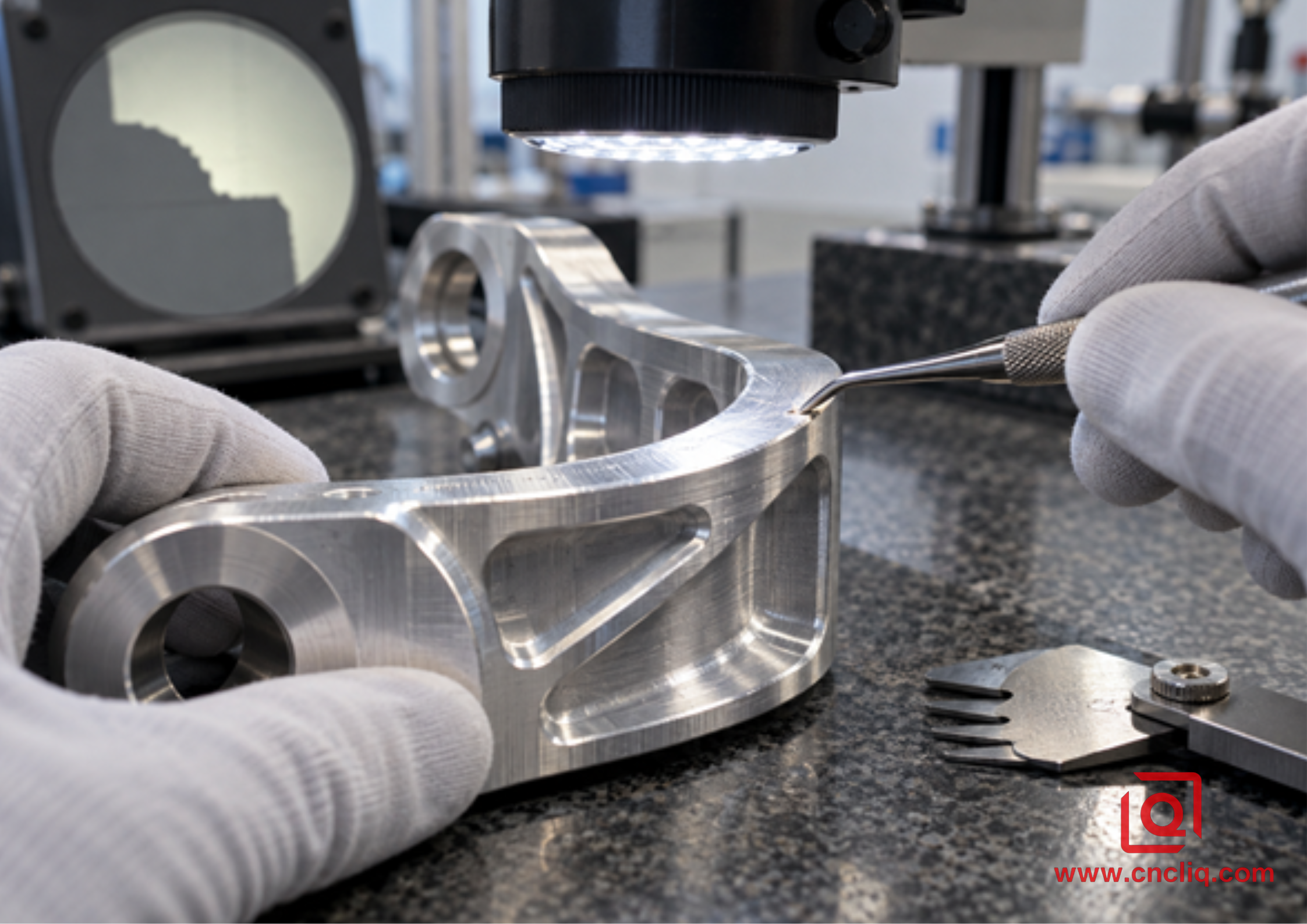
Close-up inspection of a freshly milled aluminum edge beside a digital microscope
1. Start with Alloy, Temper, and Edge Function
An RFQ that says only aluminum leaves a large process gap. 6061-T6 may be the familiar shop choice, but 6082-T6 and 7075-T6 will not copy its strength, ductility, chip behavior, or finishing response. Cast stock brings silicon and porosity into the conversation, so edge wear can change again. Material certificates, heat numbers, and temper matter when a stable production window must be repeated.
Also define what the edge must do. A hidden clearance edge may accept a controlled 0.2 mm chamfer. A gasket land, sealing edge, electrical contact face, bearing seat, or cosmetic border may need a different edge-break rule. On the drawing, replace vague notes such as deburr all edges with an allowable edge condition where function justifies it. State whether dimensions apply before or after anodizing because the final edge must survive both machining and surface treatment. Our guide to finishing options for CNC-milled aluminum parts explains why edge condition, masking, and coating allowance belong in one planning discussion.
2. Choose an Aluminum Tool That Cuts Instead of Ploughing
For high-feed work, the label carbide end mill is not enough. Look for a sharp cutting edge, positive rake, generous and polished chip space, appropriate helix, and geometry approved by the manufacturer for the alloy and operation. A polished flute reduces chip friction and makes adhesion less likely. Low-friction coatings may help in suitable applications, but a coating cannot rescue a blunt edge preparation or blocked flute.
Flute count should follow the feature. Deep full-width slots need room for chips; open adaptive paths can often use more tooth engagements. Liqin’s comparison of 2-flute and 3-flute carbide end mills for aluminum covers that selection in detail. For burr control, the additional question is whether every tooth shares the load. Excessive runout turns a nominal 3-flute cutter into one overloaded edge followed by two rubbing edges. That imbalance accelerates wear, raises local heat, and creates a burr that appears directional.
Check the holder taper, collet or hydraulic chuck, tool shank, and spindle interface as one assembly. Measure close to the cutting end where practical. Keep projection only as long as the feature requires; a shorter, stiffer assembly often improves the edge more than a small feed adjustment.
3. Control Chip Thickness, Not Just the Feed Override
High-feed milling works when the edge forms and evacuates a stable chip. It fails when feed becomes a substitute for process design. Start from the exact toolmaker’s cutting data and apply corrections for radial engagement, axial depth, reach, slotting, machine power, fixture compliance, and coolant access.
|
Process variable |
Safer validation direction |
Why it affects burrs |
Evidence to watch |
|
Feed per tooth |
Keep within toolmaker’s approved application window |
Too light can rub; too heavy can raise exit force and deflection |
Chip form, spindle load, exit-edge shape |
|
Radial engagement, ae |
Keep low and constant for adaptive high-feed roughing |
Controls engagement angle, heat, and force spikes |
Load trace through corners and narrow channels |
|
Axial depth, ap |
Use effective edge while respecting rigidity |
Changes force location and side-burr height |
Wall deflection, chatter, wear band |
|
Spindle speed |
Pair every rpm change with a feed recalculation |
Feed left unchanged alters chip thickness |
Sound, adhesion, surface smear |
|
Finish stock |
Leave a uniform, small allowance validated for the wall |
Uneven stock creates uneven final force |
CAM rest-material view and measured wall |
|
Tool-life limit |
Set from burr growth and dimensional stability |
A worn edge increases force before catastrophic failure |
Burr trend, runout, load, edge images |
A controlled test changes one major factor at a time. Record the original and revised chip load, engagement, tool-life count, burr result, surface finish, and cycle time. If feed is reduced, verify that the edge is still cutting. If feed is increased, verify that the exit edge and fixture can carry the additional instantaneous force.
4. Program the Exit Before You Program the Middle of the Cut
The cutter’s final contact with the workpiece is often more important to burr formation than the long, stable section of the path. As the tooth approaches an outer edge, the material supporting the uncut chip becomes thinner. If cutting force pushes that ligament outward, the metal bends and rolls instead of separating.
Seco Tools’ technical article Controlling Mechanical Loads in Milling Operations emphasizes cutter positioning and entry/exit strategy because milling teeth see an intermittent load. In climb milling, the tooth generally enters at greater chip thickness and exits toward zero; this often reduces the rubbing associated with conventional milling and sends chips behind the cutter. Yet always climb mill is not a complete burr plan. The specific edge orientation, part stiffness, backlash, fixture, and toolpath exit angle still decide where material is pushed.
Use these CAM moves deliberately:
1. Move profile start and stop away from a critical cosmetic or sealing edge.
2. Use a lead-out arc or tangential extension so the cutter does not snap directly off a weak corner.
3. Change direction or sequence so final material is cut toward supported stock rather than peeled away from it.
4. Machine fragile intersections before surrounding support is removed, or leave a temporary bridge finished later.
5. Avoid sudden engagement spikes in internal corners; maintain a controlled engagement angle.
6. On a critical edge, use a separate finishing path with uniform stock and a fresh tool when the drawing justifies it.
For multi-sided housings, a stable setup may keep edge relationships and cutter access under better control. The practical limits are discussed in our multi-axis CNC milling guide for complex aluminum parts.
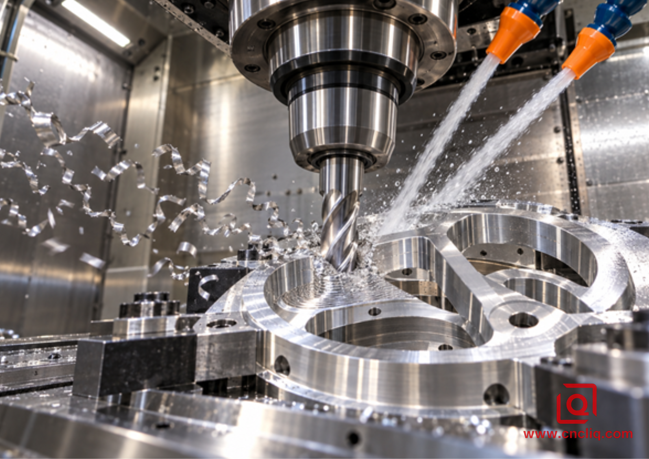
High-feed aluminum pocket milling with controlled chip evacuation
5. Keep Chips and Built-Up Edge Out of the Finish Pass
At high material-removal rates, a good cutter can produce chips faster than a poorly aimed nozzle removes them. Chips left in a pocket are cut again, dragged across the wall, or packed into a flute. Friction rises; aluminum adheres to the edge; and effective geometry becomes blunt and irregular. The next tooth pushes material instead of shearing it cleanly.
Aim a coherent air or coolant stream at the cutting zone at depth, not at the toolholder above the part. Watch for ribs or pocket walls that block the stream later in the operation. When one nozzle loses line of sight, use another direction, through-tool delivery where supported, or a path that carries chips toward an open side. Stop safely if sound changes, spindle load trends upward, or a bright aluminum cap appears on the edge.
Do not send a roughing tool covered with embedded chips across a critical finish boundary. Clean the pocket, verify the edge, and use a dedicated finishing tool when the drawing justifies it. This matters before anodizing, where a smeared or torn edge will not be repaired by chemistry.
6. Support Thin Walls, Tabs, and Breakthrough Edges
A cutter can be perfectly sharp and still leave a burr when the workpiece moves. Thin walls, sheet-like floors, corner tabs, and small openings may deflect under a high-feed pass. As the tool exits, the local edge behaves like a spring. It moves away, then returns after the tooth has passed, leaving a flexible lip.
Place clamps and supports close to the cutting zone without distorting the part. Use soft jaws, vacuum fixtures, sacrificial backing, or temporary stock where appropriate. Sequence work so heavy roughing occurs while the billet is still stiff. Leave balanced stock, rough both sides when stress relief matters, and complete the delicate edge after the part has stabilized.
For a custom precision aluminum light housing, the best solution may combine fixture support, short tools, controlled engagement, and a separate edge-forming pass rather than relying on a manual deburring bench. That product link illustrates the type of machined housing involved; final choices still depend on the approved drawing.
7. Build Burr Control into Tool-Life Management
A cutter does not have to snap to be finished. We often see the edge stay in one piece while its clean-exit ability fades. The program still reports the same cycle time, yet the burr creeps upward and the bench work grows. At that point the useful tool life is already over.
Set a practical threshold tied to the part. It might be a maximum burr that passes a comparator, a defined edge-break gauge, a microscope-image standard, a rise in deburring time, a surface-finish change, or a spindle-load trend correlated with inspected parts. Sample early enough to catch drift before an entire lot reaches secondary finishing.
Track tool identity, holder, runout, parts cut, alloy lot, operation, and inspection result. When a replacement tool restores the edge, wear is likely. When the burr stays on the same side with a new tool, investigate runout, fixture tilt, cutter path, or local support.
Anonymous Composite Case: 6061-T6 Electronics Cooling Frame
An anonymized composite OEM inquiry involved a 6061-T6 electronics cooling frame with an open central pocket, thin perimeter walls, two connector windows, a gasket ledge, and later clear anodizing. The example is a sanitized process illustration, not a disclosure of one customer’s confidential drawing and not a guaranteed result for other parts.
The trial route paired aggressive adaptive roughing with one long perimeter contour. On the stopwatch it looked good. On the bench it did not: feather burrs showed up at both connector-window exits, and one unsupported corner carried a heavier rollover. The thin ledge also made hand cleanup awkward and inconsistent.
The engineering review did not begin by lowering the entire program feed. It mapped each burr to cutter direction and remaining support. The roughing path stayed at controlled radial engagement, while the finish sequence changed in four ways. Connector windows were finished before the surrounding pocket removed their support. The critical gasket ledge received uniform finish stock. Lead-outs moved to non-sealing areas with tangential extensions. A short, sharp aluminum finishing tool received a life limit based on edge inspection rather than fracture.
Inspectors then compared the first piece, one from the middle, and the last piece in the planned tool window. The heavy rollover disappeared; a light, repeatable finish operation produced the edge break shown on the drawing. That result mattered beyond machining. Less handwork meant less variation, a simpler inspection decision, and fewer unknowns in the quotation.
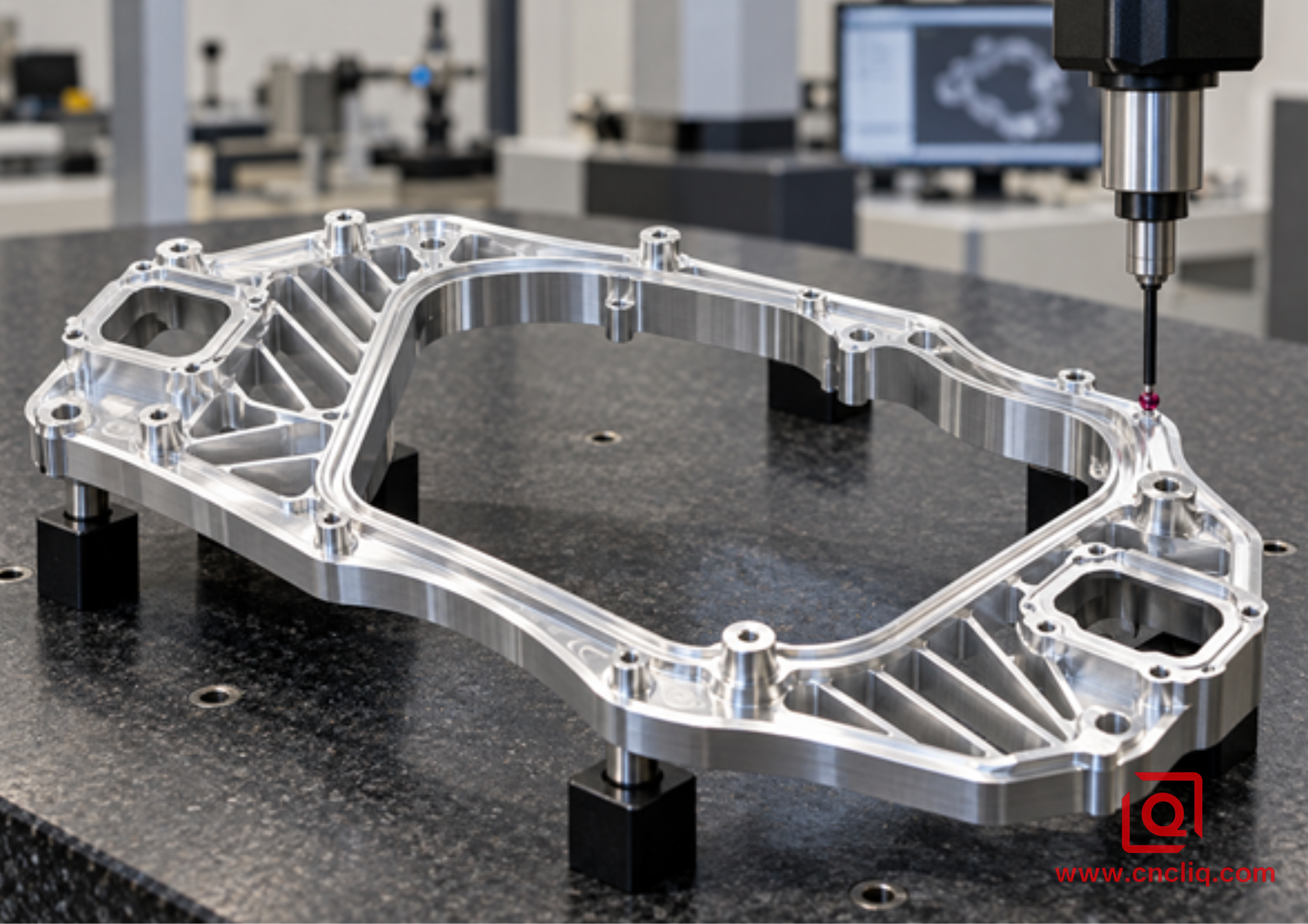
Finished 6061-T6 cooling frame under CMM inspection
A Practical Troubleshooting Sequence
When burrs appear, work through the system in a fixed order so one correction does not hide another fault.
1. Confirm the exact alloy and temper against the drawing and material certificate.
2. Mark the burr location, direction, height or acceptance result, and when it appears in tool life.
3. Inspect the cutting edge for wear, chips, aluminum adhesion, and coating damage.
4. Check holder cleanliness, tool seating, runout, projection, fixture rigidity, and local part support.
5. Review actual feed per tooth and radial chip thinning, not only the feed-override percentage.
6. Replay the CAM path at the failing edge; note engagement spikes, lead-out direction, and remaining support.
7. Verify that air or coolant reaches the cutting edge at the deepest and most obstructed point.
8. Run a controlled comparison by changing one major variable, then measure burr, finish, dimension, and cycle time.
9. Lock the successful setup into the work instruction, inspection plan, and tool-life rule.
It may feel slower than guessing for ten minutes. It is far quicker than guessing through a week of production.
Inspection and RFQ Details That Prevent Surprises
Serial work needs an edge rule that two inspectors can apply the same way. Consistent lighting may be enough for a harmless clearance edge. A sealing or assembly edge may call for a comparator, optical measurement, profilometry, or a go/no-go sample. Say what is being controlled: loose metal, rollover, sharpness, or maximum edge break. If secondary deburring is allowed, mark the sealing lands, thread starts, fits, and cosmetic faces that the operator must leave alone.
For a useful quotation, send the STEP model and controlled 2D drawing together. Include material grade and temper, critical dimensions and datums, annual volume and batch size, surface finish, coating, cosmetic zones, edge-break requirements, inspection documents, and packing expectations. Highlight thin walls, deep pockets, inaccessible intersections, and any edge that previously caused assembly trouble.
Quoting a custom bracket, housing, manifold, cooling frame, or robotics part? Send Liqin the drawing, alloy, quantity, critical edges, and target finish. We can review cutter access, support, exit strategy, deburring allowance, inspection, and production risk before pricing the job. Request a manufacturing review and competitive quote.
FAQ
1. Does increasing feed always reduce burrs in aluminum milling?
No. A higher feed can create a more decisive chip and sometimes produce a smaller secondary burr, but it can also raise cutting force, wall deflection, and exit-edge rollover. The result depends on actual chip thickness, tool sharpness, engagement, alloy, support, and exit geometry. Use the cutter manufacturer’s approved data and validate one change at a time on the real setup.
2. Is climb milling always the best direction for a burr-free aluminum edge?
Climb milling is commonly preferred on rigid CNC equipment because it starts with greater chip thickness and reduces the rubbing associated with a near-zero-thickness entry, but it is not an automatic burr-free rule. The critical edge orientation, cutter exit angle, backlash, fixture stability, and remaining material support must still be reviewed in CAM and confirmed on inspected parts.
3. Should we add a chamfer operation or eliminate the burr at source?
First reduce the primary burr through tool condition, chip thickness, path direction, support, and evacuation. Then use a controlled chamfer or edge-break operation when the drawing requires a repeatable safe edge. A defined machined edge is more consistent than uncontrolled handwork, but it adds access, tool, and cycle-time requirements that should be included in the quotation.
4. Why does the burr get worse near the end of a production batch?
Progressive cutting-edge wear, aluminum adhesion, coolant drift, or tool runout can raise forces before the cutter visibly fails. Compare first, middle, and late parts; inspect the edge under magnification; review load trends; and confirm coolant concentration and aim. Set the tool-life limit from edge quality and dimensional stability rather than waiting for breakage.
5. What should a buyer send for an accurate high-feed aluminum milling quote?
Provide a STEP model, controlled 2D drawing, alloy and temper, quantities, critical datums and tolerances, surface roughness, coating, cosmetic zones, edge-break limits, inspection or certification needs, and delivery target. Identify deep pockets, thin walls, sealing edges, connector windows, and any history of burrs or assembly interference so the supplier can price the real process instead of hidden risk.
Summary
Minimizing burr formation in high-feed aluminum CNC milling requires a controlled system: verified alloy and edge requirements, a sharp positive aluminum tool, real chip thickness, constant engagement, a planned cutter exit, effective chip evacuation, rigid support, and a tool-life limit linked to inspection. Solve the burr where it forms, then use a defined finishing operation only where the drawing needs it. This reduces manual variation, protects functional edges, and gives buyers a clearer path from RFQ to stable production.
Contact Information
Company: Ningbo Liqin Industry Co., Ltd.
Daily customer maintenance & after-sales support:service@shturl. zhuwanying@cncliq.com
New inquiry, quotation & order discussion:business@shturl. zhouli@chinaliqin.com
Hotline: +86 18757148656
Disclaimer
All technical articles, material specifications, machining recommendations, and surface treatment details published on this blog are for informational and reference purposes only. Please note that general blog insights do not replace signed technical agreements. Because custom parts vary by material heat numbers, machine calibrations, and specific tolerances, binding quality specs are governed solely by your approved CAD drawings, signed contracts, and formal quality plans.
All customer case studies featured on this blog have been thoroughly anonymized and sanitized. The performance metrics, manufacturing workflows, and imagery displayed serve solely to demonstrate our custom machining capabilities and do not represent a single universal standard for all orders.
Liqin Manufacturing Team
Built on 18 years of precision engineering experience, Ningbo Liqin Industry manufactures high-tolerance metal components for demanding global markets. We operate out of a 6,500 m2 production hub equipped with over 150 machines, running 4-axis and 5-axis CNC machining, mill-turn machining, cold extrusion, and pressure die casting under one roof. This setup allows us to manage projects seamlessly, taking parts from initial CAD concepts directly to finalized shipments.
We handle quality control with zero compromise. We treat tight tolerances with the engineering discipline they require. Backed by ISO 9001, ISO 13485, and IATF 16949 certifications, our QA engineers run strict IPQC, FQC, and OQC checks on every single production batch. From CMM dimensional mapping and optical profiling to hardness and salt-spray testing, we validate your critical specs upfront—so you receive drop-in ready components with zero assembly headaches or costly line stoppages. On top of manufacturing, you can rely on us for two-hour response times on new RFQs, direct support for prototype sampling, and smooth export shipping across Europe, North America, Asia, and Oceania.
Welcome your inquiries and samples. Visit our website or contact us directly for a competitive quote!
