 English





Are you still fighting aluminum threads that look clean but stop a GO gauge halfway, or pass inspection at the machine and tighten after anodizing? This guide explains how to choose a thread mill, prepare the pilot hole, control pitch diameter, and verify the result without turning a valuable component into a test piece. The aim is not a perfect number copied from a catalog. It is a repeatable shop method for custom aluminum parts, from the first programmed orbit to the final inspection report.
Thread milling is attractive because the cutter is smaller than the finished thread and follows a helical path. That lowers the trapped-chip risk of a tap, makes blind holes easier to manage, and lets cutter compensation correct size without rewriting the whole program. It is especially useful for expensive manifolds, housings, prototype parts, large threads, interrupted features, and jobs where one broken tap could scrap hours of machining. It is not automatically the fastest answer for every high-volume, shallow, standard thread. The decision starts with the drawing, material condition, hole geometry, acceptance method, and real cost of failure.
1. Define the Thread Before Choosing the Cutter
The callout must be complete. For metric work, confirm nominal diameter, pitch, internal or external form, right- or left-hand direction, tolerance class, engagement length, and whether the thread is straight or tapered. For Unified inch threads, confirm the series and class, such as UNC or UNF and 2B or 3B for an internal thread. A buyer should not leave the supplier to infer a class from a mating screw.
Metric general-purpose thread tolerances are covered by ISO 965-1:2026, while common limits of size are addressed by ISO 965-2:2024. Unified inch thread forms are covered by ASME B1.1-2024. Inspection requirements should also be named: ISO 1502 remains the reference for gauges and gauging of ISO general-purpose metric threads, while ASME B1.2-2025 covers gauges and gauging for Unified inch threads. These references matter because nominal diameter alone does not define an acceptable thread.
Pitch is the axial distance advanced during one complete helical revolution. Pitch diameter is the imaginary diameter at which thread ridge and groove widths are equal. It is usually the functional size that decides whether the mating part assembles with the intended allowance. Major diameter, minor diameter, flank form, lead, roundness, burrs, and surface condition still matter. A GO plug entering does not excuse a torn crest, damaged first thread, or a hole drilled off position.
Before CAM work begins, record these six items on the process sheet:
1. Complete thread designation and applicable drawing revision.
2. Material alloy and temper, including whether the part is wrought, cast, or extruded.
3. Usable full-thread depth, blind-hole bottom clearance, and entry chamfer.
4. Required inspection method and gauge revision.
5. Surface treatment, masking, and whether acceptance is before or after finishing.
6. Quantity, prototype approval plan, and expected production life.
This front-end discipline improves quotation quality. If your project includes multi-face ports or deep intersecting passages, our guide to deep-hole drilling and rigid tapping in aluminum explains why bottom clearance and chip escape need to be resolved before the thread cycle.
2. Choose a Thread Mill That Fits the Hole and the Job
Thread mills fall into two practical groups. A single-form cutter has one cutting profile or a short cutting section. It can machine different diameters that share a compatible pitch and form, and its shorter engagement usually reduces cutting force. It is a strong choice for prototypes, unusual diameters, deep threads, thin walls, and machines where rigidity is limited. The tradeoff is more helical travel and a longer cycle.
A multi-row or full-profile cutter carries several thread teeth along its cutting length. It can generate the full threaded length in roughly one helical revolution when its cutting length matches the requirement. That improves output on repeat production, but the tool is dedicated to a pitch and practical depth range, applies more load at once, and needs good chip evacuation. It is less forgiving when the wall is slender or the holder has excessive runout.
For small internal threads, solid carbide is usually the practical base material because it combines edge sharpness and stiffness. Aluminum wants a keen, positive cutting edge and generous, polished chip space. Uncoated polished carbide can work well. Coatings designed for nonferrous cutting, including suitable ZrN or DLC variants, may reduce adhesion, but the cutter maker’s application data comes first. A thick or blunt coating intended for steel can increase rubbing and built-up edge in gummy aluminum.
Tool diameter is a balance. A larger cutter is stiffer, but as cutter diameter approaches the thread’s minor diameter, clearance falls and geometric profile error can rise because a straight cutter is generating a helix. SmiCut’s thread-milling guidance identifies cutter-to-thread diameter, profile angle, and pitch as key influences on profile deviation. The safe choice is not simply the largest tool that can enter the hole. Use the manufacturer’s selector or calculation software, confirm the minimum bore and pitch range, and simulate the approach and retract path.
Reach also deserves a hard check. Keep the cutter and holder as short as the feature allows. Increasing stickout raises deflection and makes compensation look unstable even when the nominal tool diameter is correct. For a deep blind thread, use a neck length that clears the bore without rubbing, but do not buy unnecessary reach. Hydraulic chucks, shrink-fit holders, or precision collet systems may be appropriate depending on diameter and machine, provided measured runout meets the toolmaker’s limit. Clean both taper and holder. A small chip trapped at the interface can consume a meaningful part of a tight pitch-diameter tolerance.
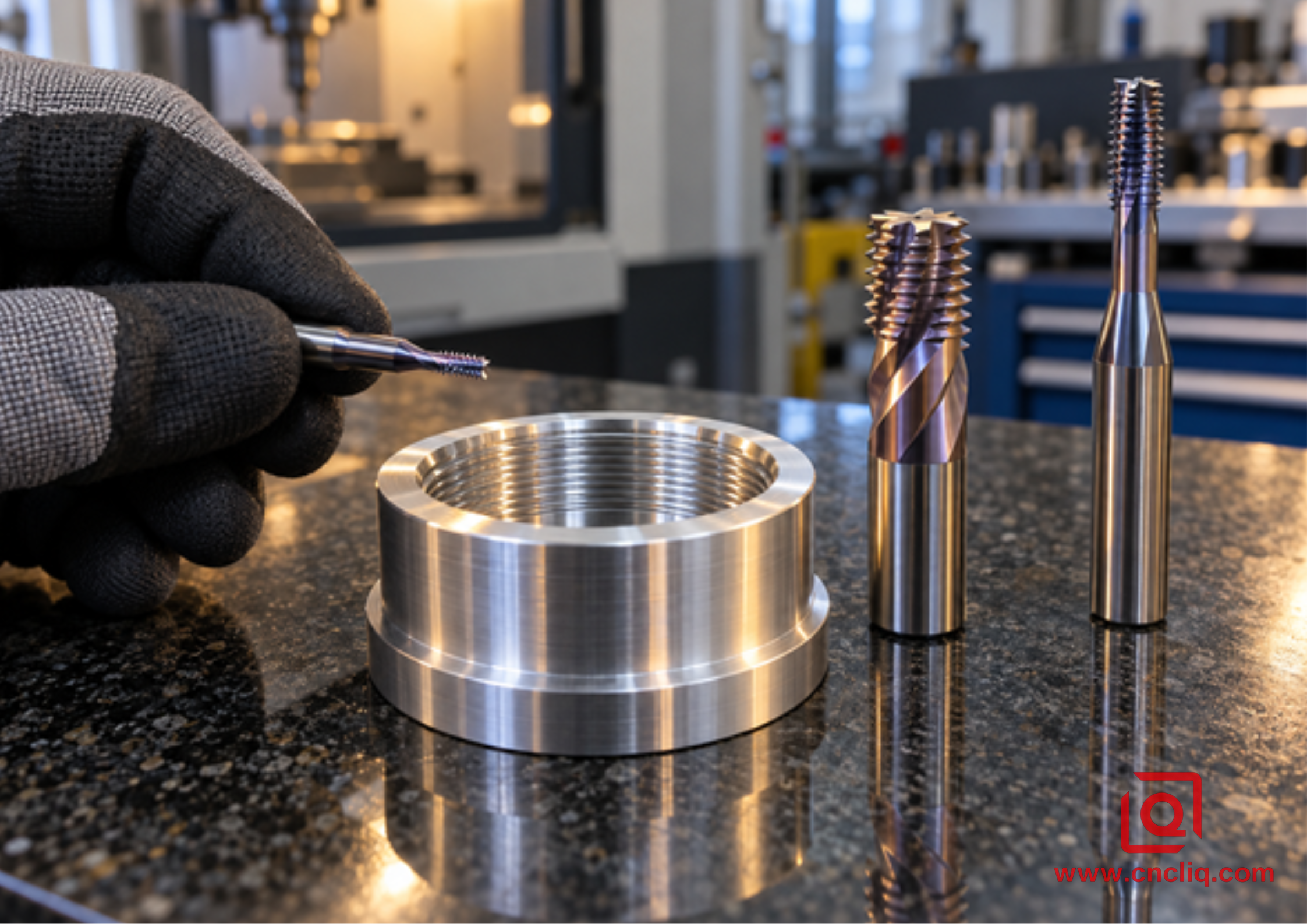
Three thread-mill styles beside a machined aluminum ring
|
Selection question |
Single-form cutter |
Multi-row cutter |
Shop-floor implication |
|
Several diameters with one pitch |
Often suitable within maker limits |
Usually limited to a defined family |
Single-form reduces tool inventory |
|
Deep or obstructed thread |
Usually more flexible |
Cutting length and neck can limit access |
Verify shoulder and bottom clearance |
|
Thin wall or delicate boss |
Lower simultaneous engagement |
Higher radial load |
Use lighter radial passes if the wall moves |
|
Repeat production |
Longer cycle |
Faster when the feature matches |
Compare tool cost with saved spindle time |
|
Nonstandard diameter |
Strong option |
May require a special tool |
Confirm profile and pitch compatibility |
|
Tight first-part control |
Easy to correct with wear offset |
Correctable, but runout affects several teeth |
Measure actual cutter and prove the process |
3. Match the Tool to the Aluminum Alloy
Do not treat all aluminum as the same material. 6061-T6 is a common, balanced choice and generally machines predictably, yet it can still smear onto a dull edge when chip load falls too low or coolant delivery misses the cut. 7075-T6 or T651 is stronger and often forms a cleaner chip, but a small thread mill still demands a rigid setup and conservative proofing because carbide is brittle. Softer 5xxx-series material can be more adhesive. Cast aluminum behavior also changes with silicon content and casting quality.
The alloy and temper belong on the RFQ and inspection traveler. For broader material, spindle, and tool-selection context, see our 6061 aluminum feeds, speeds, and tooling guide. If the print only says “aluminum,” pause before selecting parameters. The difference affects edge buildup, chip shape, tool life, finish, and the stability of the first-piece offset.
4. Prepare the Pilot Hole and Entry Correctly
Thread milling does not repair a bad pilot hole. The hole must be on position, straight enough for the thread length, round, and sized to the drawing and standard. Walter’s threading technical compendium gives pitch-dependent pilot-hole tolerance recommendations as a practical manufacturing reference, but the final allowable size must come from the specified thread limits and inspection plan. Never replace the print with a generic “nominal minus pitch” rule when tolerance, crest condition, or special form matters.
For a blind feature, model the complete stack: drill point, desired full-thread length, cutter runout, lead-in move, cutter bottom clearance, chip space, and any sealing shoulder. A thread mill can cut closer to the bottom than many taps, but it still needs room to enter, interpolate, and exit without striking the floor. A controlled chamfer helps the fastener start and removes the sharp burr at the first thread. Too much chamfer reduces effective engagement and can expose an oversized mouth after anodizing.
5. Program the Helix Without Creating a Hidden Size Error
During one 360-degree orbit, the Z axis moves exactly one thread pitch for a single-start thread. The CAM system calculates the cutter-center path from the target thread size and tool geometry. Use climb milling where the toolmaker and machine setup support it, and enter or leave with a smooth tangential arc rather than plunging radially into full engagement. Simulate the cycle with the real tool assembly, holder, bore, fixture, and stock condition.
The programmed feed deserves special attention. The cutter center travels on a smaller circle than the cutting edge at the thread diameter, so a control or CAM system may apply feed differently. Allied’s thread-milling reference guide distinguishes linear feed from the corrected feed used on the circular path. Confirm whether the posted value is centerline feed or cutting-edge feed and whether the control performs arc-feed compensation. A surprising feed jump in a small bore can chip the cutter or leave a lobed thread.
One radial pass may be enough in stable aluminum applications, but it is not a universal requirement. Use two or more radial passes when the thread is large or coarse, the cutter is slender, the wall is flexible, finish is critical, or the first pass shows chatter. A spring pass can remove elastic recovery, yet repeated zero-stock passes may rub and build aluminum on the edge. Make each pass intentional and validate it by measurement.
6. Control Pitch Diameter With Measured Data
Pitch control starts with the actual cutter, not the nominal catalog diameter. Many thread mills are supplied with a measured programming diameter or correction value. Enter that value exactly as the manufacturer defines it. Do not assume it is the maximum outside diameter, shank diameter, or CAD model diameter. Walter’s documentation shows how measured cutter data and a defined correction can place a milled thread near the middle of its tolerance range.
Prove the first part with a conservative offset that leaves the internal thread slightly tight, then measure and move toward the target in controlled increments. The sign of compensation varies by control, CAM strategy, and whether the offset represents radius, diameter, geometry, or wear. Establish the sign on a test piece or safe first article. Record every change. A note such as “plus 0.02” is dangerous if the next operator does not know which register or convention it describes.
A robust correction loop looks like this:
1. Warm the machine and stabilize coolant according to the normal precision routine.
2. Measure cutter runout near the cutting section and confirm holder cleanliness.
3. Machine the pilot hole and thread using the approved baseline program.
4. Deburr and clean the feature without rounding the first functional thread.
5. Gauge at the specified temperature with the approved method.
6. Apply a small change in the designated wear field and cut a new feature or approved test coupon.
7. When the result is centered, freeze the setup sheet and define a wear-monitoring frequency.
Temperature matters. Aluminum’s coefficient of thermal expansion is roughly 23 micrometres per metre per degree Celsius near room temperature. A warm part, warm gauge, and cool inspection room can consume margin when tolerances are tight. Let the part and gauge stabilize under the agreed inspection condition before making the final compensation decision.
Do not use compensation to hide another problem. If the GO gauge enters at the mouth but binds deeper, investigate taper, cutter deflection, runout, chip recutting, and thermal condition. If results drift in one direction across a batch, inspect the edge for wear or aluminum adhesion. If size alternates between parts, look for chip contamination in the fixture, inconsistent clamping, or unstable toolholding.
7. Inspect Function, Not Appearance Alone
A bright thread can still be wrong. For common internal metric threads, use calibrated GO and NO-GO plug gauges specified by the quality plan. The GO gauge checks the functional thread through the required engagement, while the NO-GO gauge checks that the thread has not exceeded the applicable limit under the governing standard and shop procedure. Follow the gauge standard and documented acceptance rule; do not force either member.
For Unified inch threads, use gauges and acceptance methods consistent with the drawing and ASME requirements. Optical measurement, CMM scanning, or thread measurement systems may support process development, special forms, and failure analysis, but they do not automatically replace the specified functional gauge. A pitch gauge identifies pitch; it is not a precision acceptance tool for pitch diameter.

Operator checking an aluminum valve body with a GO plug gauge
Inspection should include the feature around the thread. Confirm the entry chamfer, burr condition, position where required, usable depth, and bottom cleanliness. On fluid manifolds, check that intersecting passages are free of chips and that the thread does not break into a sealing land. Our custom aluminum hydraulic manifold page shows a component where thread form, sealing compatibility, channel cleanliness, and dimensional inspection must work as one process.
8. Plan for Anodizing Before Cutting the First Thread
Anodizing converts the aluminum surface and changes the relationship between the machined substrate and finished feature. The effect on a thread depends on alloy, bath, coating type and thickness, masking, and the drawing’s finished-size requirement. Do not subtract a generic coating number from pitch diameter and call the problem solved. Coordinate the machining supplier, finisher, and gauge plan before production.
Threads may be masked and accepted essentially as machined. They may be anodized to a validated pre-finish target so the final thread gauges correctly. Or critical threads may be machined after coating when the design and corrosion requirements allow exposed aluminum. Each route has different risks for corrosion protection, fit, electrical contact, burrs, and scheduling.
State whether the gauge requirement applies before or after finishing. Include representative threaded coupons or first articles when finish buildup is significant. Protect the thread from blasting media and chemical residue. After finishing, clean the bore and recheck it with the specified gauge. For more on coating growth and masking, see our aluminum post-processing guide.
9. Anonymous Customer Case: Blind Threads in a Thin-Wall Cooling Housing
An industrial electronics customer requested machined 6061-T651 cooling housings. Each had eight blind M6 x 1 internal threads around a thin ribbed perimeter. The threads accepted cover screws and had to remain functional after the specified anodizing process. The sourcing package identified the thread and coating, but did not say whether gauging applied before or after finishing. That ambiguity was the largest risk.
During DFM review, the team clarified finished-part gauging, masking, full-thread depth, and the mating screw. Pilot holes were produced in the same primary setup as the locating datums so thread position did not depend on a second manual re-clamp. A small solid-carbide single-form thread mill was selected instead of a rigid tap. This reduced broken-tool risk in an almost-finished thin-wall component and allowed pitch diameter correction through a controlled wear offset.
The first housing was intentionally left on the tight side, cleaned, and checked with the specified gauges. A documented correction moved the result toward the center of the accepted range. Representative parts then followed the approved finishing route and were gauged again after cleaning. The control plan sampled thread function at the beginning of the run, after defined tool-life intervals, and whenever the operator observed edge buildup or changed the cutter.
The important result was not a dramatic speed claim. It was a stable approval loop: one drawing interpretation, one gauge plan, one offset convention, and traceable checks before and after finishing. That reduced the chance of discovering a systematic fit problem at assembly.
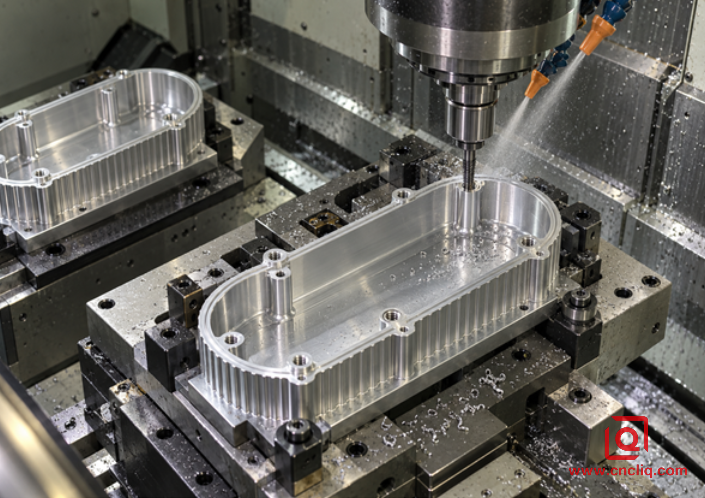
Thread milling blind bosses in an aluminum cooling housing
10. Troubleshooting Table
|
Symptom |
Likely cause |
Practical check |
Corrective direction |
|
GO gauge binds deeper |
Hole taper, deflection, chip recutting, or temperature |
Check pilot-hole form and stable gauge condition |
Improve hole, reduce reach, add a controlled pass |
|
Thread stays tight |
Wrong programming diameter or finish buildup |
Verify tool data and finish requirement |
Correct wear offset in documented steps |
|
Size drifts oversize |
Flank wear, chipped edge, runout, or wrong offset sign |
Inspect cutter and offset history |
Replace tool, correct holder, restore baseline |
|
Torn or gray flanks |
Built-up edge, rubbing, weak chip evacuation |
Inspect flutes for adhered aluminum |
Use sharp nonferrous geometry and restore chip load |
|
Chatter bands |
Excessive stickout, weak boss, unstable holder |
Check overhang, support, and runout |
Shorten assembly and split engagement |
|
Heavy entry burr |
Poor chamfer, worn edge, abrupt exit |
Inspect first thread and lead-out |
Add a controlled chamfer and tangential exit |
|
Tight only after anodizing |
Finish effect missing from plan |
Compare pre- and post-finish data |
Validate masking or a pre-finish target |
|
Random variation |
Dirty fixture, clamp variation, unstable temperature |
Audit consecutive parts |
Clean, standardize clamping, stabilize inspection |
11. What to Send With an RFQ
Send the native 3D model or STEP file with a controlled 2D drawing. Mark critical threads and datums. Include alloy and temper, thread standard and class, full-thread depth, quantity, coating or masking requirement, inspection standard, gauge expectations, first-article documents, and mating hardware when fit is unusual.
State whether the supplier may propose a thread insert, different engagement length, or process change. Thread milling may suit a high-value blind feature, while tapping or forming may be more economical for a large run of shallow standard holes. The thread plan also has to suit the machine layout and the other features. Our comparison of 3-axis, 5-axis, and mill-turn routes for aluminum parts gives useful context for that choice.
A useful RFQ starts with the drawing and expected annual volume. On a manifold or housing, we look first at tool access and the space below each blind thread. We then check reach, class, finishing order, and the inspection note before pricing. This short review often catches an expensive detail while it is still easy to change.
FAQ
1. Is thread milling always better than tapping aluminum?
No. Thread milling is valuable when breakage risk, blind-hole chip control, adjustable pitch diameter, an unusual thread, or a high-value component justifies the extra cycle time. A well-controlled tap can be faster for high-volume standard threads. The correct choice depends on geometry, alloy, machine capability, quantity, tolerance, and the cost of a failed feature.
2. Can one thread mill cut several thread diameters?
A single-form cutter can often cut several diameters that use a compatible form and pitch, provided the cutter maker approves the range and the tool clears the pilot hole. A multi-row cutter is usually more dedicated. Pitch is created by the helical path, but the cutter profile must still match the required form and pitch range.
3. How do you adjust an aluminum thread that gauges too tight?
First confirm the pilot hole, tool condition, temperature, cleaning, and gauge. Then use the documented wear-compensation field to increase internal-thread size in a small controlled step. The required sign depends on the CNC control and CAM convention, so prove it safely rather than guessing. Cut and inspect a new feature after each change.
4. Should an internal thread be gauged before or after anodizing?
The drawing and agreed quality plan should say. If the thread must function on the delivered anodized part, final acceptance normally needs to address the post-finish condition, including masking and cleaning. Pre-finish data is useful for process control, but it does not prove final fit when the coating changes functional surfaces.
5. Which details make an aluminum thread-milling quote reliable?
Send the model and controlled drawing together. Name the alloy, temper, thread callout, usable depth, datums, lot size, finish, masking, gauge, inspection documents, and delivery need. Include the mating part when the fit is unusual. Mark the threads that can stop an assembly, because those deserve the closest DFM and inspection attention.
Summary
Reliable aluminum thread milling comes from a linked process: define the thread and acceptance standard, choose a sharp cutter with suitable diameter and reach, prepare a controlled pilot hole, program the helix and feed convention correctly, set pitch diameter from measured cutter data, inspect at stable conditions, and plan anodizing before production. Share the drawing, mating hardware, finish requirement, and annual volume early so the machining and gauge strategy can be built into the quote instead of repaired after the first batch.
Contact Information
Company: Ningbo Liqin Industry Co., Ltd.Daily customer maintenance & after-sales support:service@shturl. zhuwanying@cncliq.com
New inquiry, quotation & order discussion:business@shturl. zhouli@chinaliqin.com
Hotline: +86 18757148656
Disclaimer
All technical articles, material specifications, machining recommendations, and surface treatment details published on this blog are for informational and reference purposes only. Please note that general blog insights do not replace signed technical agreements. Because custom parts vary by material heat numbers, machine calibrations, and specific tolerances, binding quality specs are governed solely by your approved CAD drawings, signed contracts, and formal quality plans.
All customer case studies featured on this blog have been thoroughly anonymized and sanitized. The performance metrics, manufacturing workflows, and imagery displayed serve solely to demonstrate our custom machining capabilities and do not represent a single universal standard for all orders.
Liqin Manufacturing Team
Built on 18 years of precision engineering experience, Ningbo Liqin Industry manufactures high-tolerance metal components for demanding global markets. We operate out of a 6,500 m² production hub equipped with over 150 machines, running 4-axis and 5-axis CNC machining, mill-turn machining, cold extrusion, and pressure die casting under one roof. This setup allows us to manage projects seamlessly, taking parts from initial CAD concepts directly to finalized shipments.
We handle quality control with zero compromise. We treat tight tolerances with the engineering discipline they require. Backed by ISO 9001, ISO 13485, and IATF 16949 certifications, our QA engineers run strict IPQC, FQC, and OQC checks on every single production batch. From CMM dimensional mapping and optical profiling to hardness and salt-spray testing, we validate your critical specs upfront—so you receive drop-in ready components with zero assembly headaches or costly line stoppages. On top of manufacturing, you can rely on us for two-hour response times on new RFQs, direct support for prototype sampling, and smooth export shipping across Europe, North America, Asia, and Oceania.
Welcome your inquiries and samples. Visit our website or contact us directly for a competitive quote!
