 English




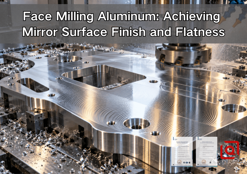
Are you still struggling with cloudy streaks, crosshatch marks, or a plate that looks flat in the vise but rocks on the inspection table? This guide explains how to face mill aluminum for a mirror-like surface and dependable flatness without turning the job into an expensive polishing exercise. It is written for design engineers, sourcing teams, and machinists who need practical answers: what to put on the drawing, what to control at the machine, how to measure the result, and what information a supplier needs before quoting.
Quick Answer: What Produces a Mirror-Like, Flat Face?
For production face milling, start with a stable wrought alloy and temper, a rigid machine, an aluminum-specific cutter, low axial runout, and clean chip evacuation. Rough both sides in a balanced sequence when residual stress is a concern. Let the part and coolant reach a stable temperature, support the work without bending it, then make a light finishing pass with a consistent chip load. Inspect surface texture and flatness as separate requirements.
Do not use the word “mirror” as the only acceptance criterion. A buyer, supplier, and inspector can interpret it differently. State a roughness value such as Ra, the permitted lay or visual standard, a flatness tolerance with its measurement conditions, and whether polishing or another secondary process is allowed. The drawing should also identify any sealing land, optical area, or cosmetic face that matters.
|
Requirement |
What it describes |
Typical control method |
Common mistake |
|
Ra or Rz |
Small-scale surface texture |
Cutting-edge geometry, feed per tooth, runout, chip control |
Treating a low Ra value as proof of flatness |
|
Flatness |
Separation of the entire surface by 2 parallel planes |
Stock stability, fixture support, machine tram, balanced material removal |
Measuring while the part is still distorted by clamps |
|
Parallelism |
Orientation of one face relative to a datum |
Datum strategy, setup control, thickness mapping |
Calling out flatness when assembly actually needs parallelism |
|
Lay |
Direction of the machining pattern |
Toolpath direction and cutter path |
Ignoring gasket or sliding direction |
|
Visual reflectivity |
Appearance under agreed lighting |
Finish process, cleanliness, handling |
Writing “mirror finish” with no measurable standard |
Mirror Finish and Flatness Are Not the Same Specification
Surface roughness records fine peaks and valleys over a sampling length. Flatness evaluates the whole surface independently of a datum. A shiny aluminum plate can be bowed, and a flat plate can have visible cutter marks. Waviness sits between those scales and may come from machine vibration, thermal drift, or clamping. That distinction matters for vacuum plates, valve bodies, heat-transfer bases, optical mounts, and gasketed housings.
For example, polishing may lower Ra while rounding an edge or changing local flatness. Likewise, a broad face mill can make a consistent reflective sweep but still leave a shallow dish if the spindle is not square to travel. Define function first. A gasket land usually needs controlled texture and lay so the seal can conform. A thermal interface may need broad contact and limited waviness. A decorative panel may prioritize a uniform reflection more than a very tight geometric tolerance.
The internationally used vocabulary is not a shop preference. ASME B46.1 addresses surface texture concepts, while ISO GPS standards distinguish geometric form from surface texture. For flatness verification, the drawing and inspection plan should agree on datum-free evaluation, point density, filtering, and the condition of the part. A result obtained on 3 support points at 20 degrees C should not be compared casually with a value measured immediately after machining on a warm, fully restrained fixture.
Choose the Aluminum Before Choosing the Speed
6061-T6 and 6061-T651 are common choices for machined plates, housings, and fixtures because they combine machinability, availability, corrosion resistance, and predictable finishing. The T651 designation indicates stress relief by stretching after heat treatment, which can improve dimensional stability in plate products. It does not eliminate residual stress, especially after large, asymmetric material removal.
7075-T651 offers higher strength and often machines cleanly, but raw material cost, corrosion behavior, and the final finish route differ. Cast tooling plate can be attractive for large vacuum tables and fixtures because it is supplied for dimensional stability, but its properties and certification need to match the application. Extrusion may be economical for a near-net section, yet its stress pattern and grain flow can make a wide cosmetic face more sensitive to distortion.
If alloy selection is still open, review Liqin’s 6061 vs. 7075 aluminum comparison before locking the drawing. For broader DFM decisions involving alloy, tolerance, and wall geometry, the aluminum CNC milling guide provides a useful next step.
Ask the supplier to preserve heat or lot traceability when it matters. Also identify plate direction on parts with demanding flatness. Two blanks with the same alloy and temper can behave differently if one comes from thick plate and the other from an extrusion. A credible quotation should therefore state the material form, not just “Aluminum 6061.”
The Cutting System: Cutter Body, Inserts, and Runout
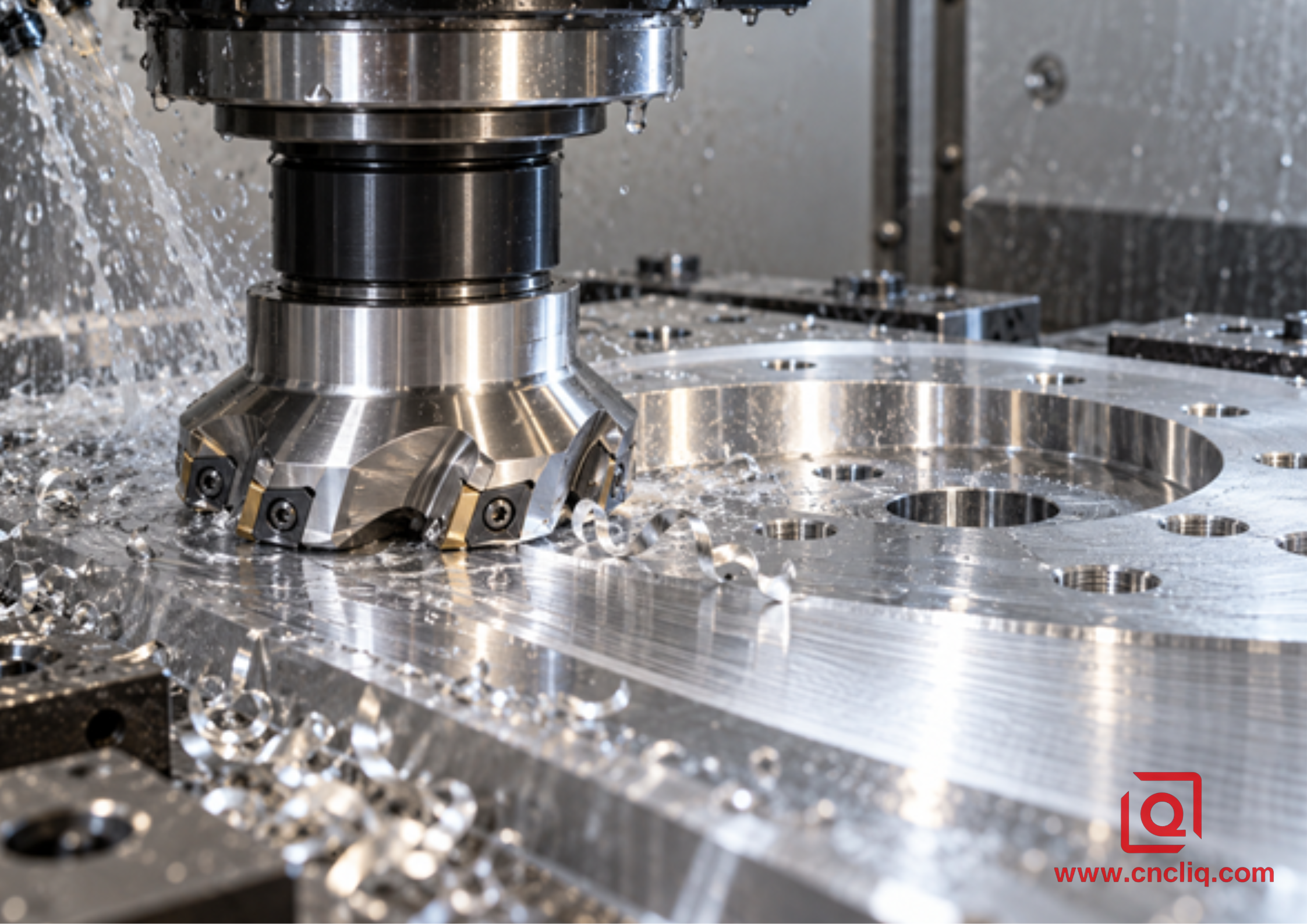
Aluminum-specific face mill making a final finishing pass
A face mill removes material with multiple cutting edges. That is productive, but every insert seat adds a potential height error. If one insert protrudes farther than the others, it may do nearly all the finishing work; if several edges sit at different heights, they can leave a repeating pattern. The result may look glossy from one angle and striped from another.
Use a cutter designed for nonferrous materials: sharp positive geometry, polished rake faces, generous chip space, and inserts intended to shear rather than plough. Uncoated polished carbide is common for general work. PCD may be justified for long production runs, abrasive high-silicon alloys, or demanding finish consistency. A wiper insert can flatten the feed marks over a wider land, but it only works when cutter setup, insert height, and spindle condition are controlled.
Before a critical finishing run, clean the spindle taper, holder, cutter pilot, insert pockets, and clamping surfaces. A small chip under an insert changes edge height. Measure axial runout at the cutting edges with the cutter mounted as it will run. There is no universal runout number for every diameter and finish requirement; the acceptable value must be materially smaller than the texture and form error budget. Record it for repeat work rather than relying on appearance alone.
Speeds and Feeds: Build a Window, Not a Magic Recipe
Copying one spindle speed from another shop is risky. Cutting speed depends on insert grade, cutter diameter, alloy, machine limits, holder balance, coolant strategy, and the manufacturer’s data. Start inside the toolmaker’s recommended range, calculate spindle speed from cutting speed and diameter, then set feed from chip load and the number of effective teeth.
Use these equations as a check:
n = (1000 x Vc) / (pi x D)
vf = n x z x fz
where n is spindle speed in rpm, Vc is cutting speed in m/min, D is cutter diameter in mm, vf is table feed in mm/min, z is the number of effective teeth, and fz is feed per tooth in mm.
|
Variable |
If set too low |
If set too high |
Shop-floor response |
|
Chip load |
Rubbing, heat, built-up edge, smeared finish |
High force, vibration, insert damage |
Change feed in controlled steps and inspect the actual chip |
|
Cutting speed |
Unstable built-up edge on some alloys |
Heat, balance risk, spindle-limit issues |
Stay within tool and machine limits; confirm holder balance |
|
Axial depth on finish pass |
Edge may rub or skip over waviness |
Excess force and distortion |
Leave a consistent, measurable finish allowance |
|
Radial engagement |
Uneven entry and exit or repeated overlap marks |
High force and temperature |
Choose a path that keeps cutter engagement predictable |
|
Coolant or air delivery |
Chips recut and weld to the edge |
Poorly aimed flow can recirculate chips |
Direct clean flow where the chip leaves the cut |
The finish pass must still cut. An extremely small programmed depth may disappear inside prior-pass waviness, spindle growth, or insert runout, causing intermittent rubbing. Leave enough stock after semi-finishing for the sharp edge to engage continuously. Once the process is stable, change one variable at a time and keep the old part as a visual master.
Built-up edge is a frequent cause of hazy bands and random tearing in aluminum. It forms when work material adheres near the cutting edge and changes the effective geometry. Sharp polished tooling, adequate chip thickness, clean lubrication, and strong chip evacuation are the first corrections. Liqin’s guide to controlling built-up edge in soft aluminum discusses the mechanism in more detail; although it focuses on turning, the lessons about rubbing, adhesion, edge condition, and chip control transfer directly to face milling.
Flatness Begins Before the Finishing Pass
The cutter cannot permanently flatten material that is being elastically bent by the fixture. When the clamps release, the part springs toward its free state. Thin plates also move as residual stress is uncovered. Heat adds another layer: aluminum’s coefficient of thermal expansion is roughly 23 x 10^-6/K, so a 400 mm length changes by about 0.046 mm for a 5 degrees C temperature difference. That simple calculation shows why a warm part and a 20 degrees C inspection room can disagree.
The main controls are straightforward:
1. Inspect raw stock for bow and thickness variation before machining.
2. Establish datums with a light cleanup instead of forcing a warped blank flat.
3. Rough both sides in a balanced sequence when geometry permits.
4. Leave uniform stock for semi-finishing and finishing.
5. Release and re-seat the part between major material-removal stages if the process plan calls for it.
6. Support the part at stable locations and apply only the clamping force needed to resist cutting.
7. Stabilize the machine, tool, coolant, fixture, and workpiece before the final pass.
8. Measure after unclamping and after thermal equalization.
Peer-reviewed research shows why process compensation can matter. In a study published in the International Journal of Machine Tools and Manufacture, researchers using a 50.8 mm face mill on aluminum reduced measured flatness error from 32 micrometers to 7 micrometers with a cutting-depth compensation method. The result should not be treated as a universal shop capability, but it demonstrates that measured system error, compliance, and toolpath compensation can materially change flatness. See the study, “Improvement of surface flatness in face milling based on 3-D holographic laser metrology”.
For large, thin parts, vacuum workholding can distribute force more evenly than a few edge clamps. It can also mask natural bow by pulling the plate against the fixture. The inspection plan therefore needs an unclamped check. For smaller plates, a qualified fixture with relieved pockets and controlled support points may be more repeatable. Fixture contact faces must be clean; a single trapped chip can tilt the work and create both flatness and parallelism errors.
Toolpath Strategy and Machine Geometry
A one-way pass often produces a more consistent lay than a back-and-forth path because cutter engagement remains similar. Climb milling is commonly preferred for finish consistency on a capable CNC machine, but the full path must avoid dwell marks at reversals and abrupt changes in engagement. Lead-in and lead-out moves should occur off the critical surface when possible.
Spindle-to-axis squareness is essential. A tilted cutter can create a concave or convex trace depending on travel direction and whether the trailing edge rubs. Verify machine geometry with an appropriate test method before blaming the inserts. Also check holder condition, spindle bearing health, axis reversal, and fixture alignment. If the surface has evenly spaced waves, calculate their pitch against spindle speed and table feed; the pattern can point toward a recurring mechanical or process frequency.
Coolant, Chips, and Surface Protection
Mirror-like aluminum is easy to damage after it leaves the cutter. Recut chips scratch the face, dirty coolant stains it, and a careless air blast can drag chips across the surface. Aim coolant or air to remove chips from the cutting zone and away from the finished path. Keep concentration and cleanliness within the coolant supplier’s limits. Avoid wiping a dry reflective face with a shop rag that may contain abrasive debris.
If the part will be anodized, plated, coated, bonded, or used as an electrical contact, decide which faces must remain bare and how the finish will be protected. Secondary finishing can alter appearance, roughness, and dimensions. Liqin’s finishing options for CNC-milled aluminum explains how as-machined, anodized, blasted, and other finishes serve different functions. Do not pay for a mirror-milled surface that a later blast operation will intentionally erase.
Measure Roughness and Flatness Separately
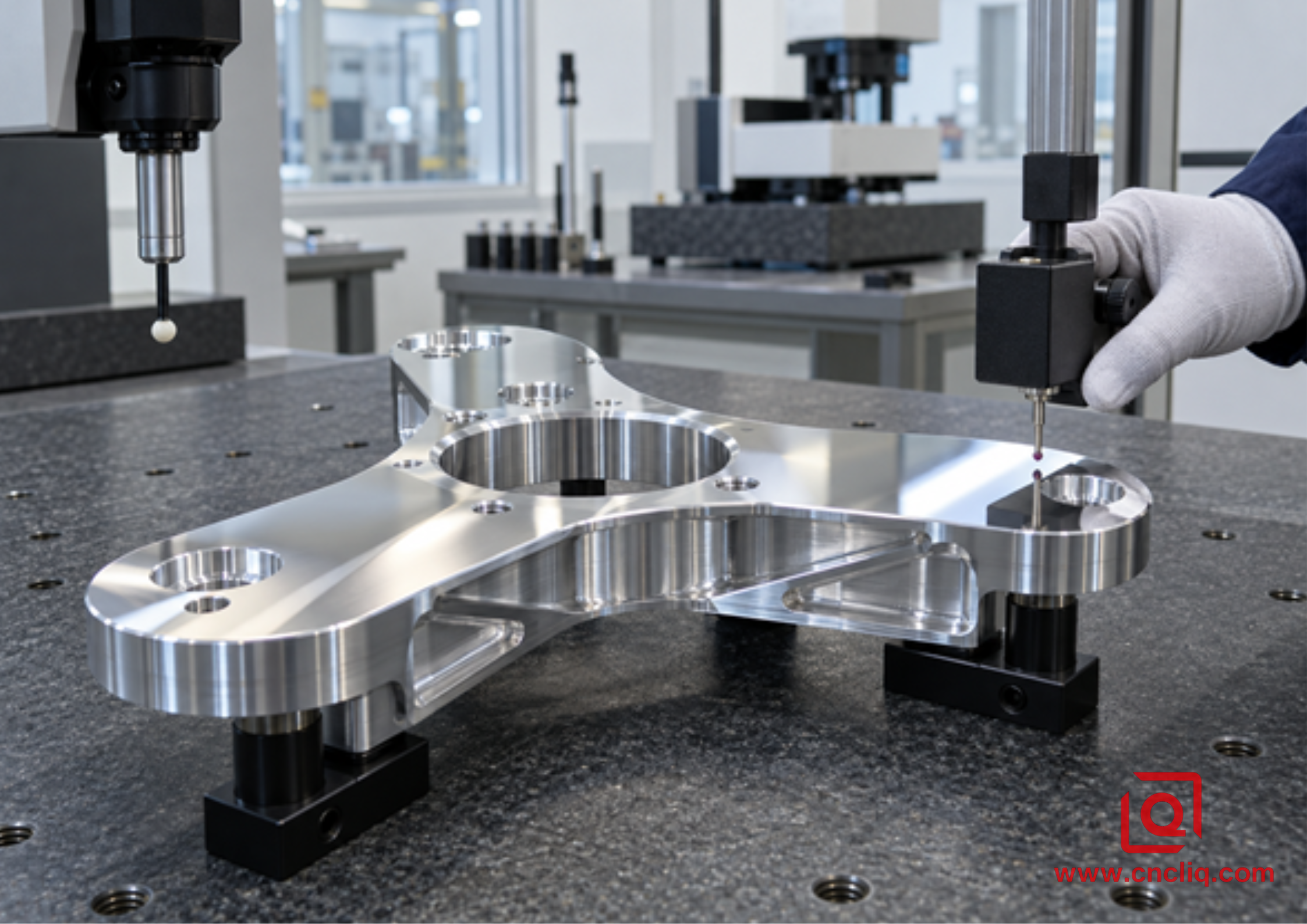
Flatness and roughness inspection of a mirror-finished aluminum part
A roughness tester samples a line. It is sensitive to trace direction, cutoff, filter, and evaluation length. Measure across the machining lay unless the governing standard or drawing specifies otherwise, and record the instrument settings. One attractive reading is not enough for a large sealing face; use a defined map of locations.
Flatness can be evaluated with a CMM, surface plate and indicator, optical equipment, or other qualified methods. Each method has uncertainty and sampling limits. The inspection plan should state the support condition, point pattern, temperature, and whether the result is filtered. For a broad plate, include edge, center, and transition zones. A dense point cloud may reveal a shallow dish that a few manual points miss.
|
Inspection item |
Recommended record |
Why it matters |
|
Surface roughness |
Ra or Rz, trace direction, cutoff/filter, evaluation length, locations |
Makes results reproducible |
|
Flatness |
Method, support points, point map, temperature, uncertainty |
Prevents fixture and sampling disputes |
|
Visual finish |
Lighting, viewing distance, approved limit sample |
Controls cosmetic expectations |
|
Cutter condition |
Tool ID, insert lot/edge, measured runout |
Links defects to the cutting system |
|
Process state |
Part temperature, coolant temperature, elapsed stabilization time |
Explains thermal variation |
An older NIST-hosted reference, Machining of Aluminum and Aluminum Alloys, remains useful for general machining behavior and underscores the importance of alloy-specific cutting practice. Use it as background, then follow current toolmaker data and the project’s approved control plan.
Troubleshooting by Surface Pattern
|
Symptom |
Likely causes |
First checks |
|
Cloudy or smeared bands |
Built-up edge, rubbing, contaminated edge |
Inspect inserts under magnification; confirm chip load and lubricant delivery |
|
Repeating insert marks |
Axial runout, dirty seat, unequal insert height |
Clean pockets; torque correctly; measure edges in the spindle |
|
Crosshatch or trailing-edge rub |
Spindle not square, cutter deflection |
Check tram and machine geometry; reduce force only after geometry is verified |
|
Chatter waves |
Weak support, resonance, worn edge, excessive engagement |
Change support and engagement; check holder and spindle condition |
|
Dish or crown |
Machine geometry, fixture bending, thermal gradient |
Inspect unclamped at stable temperature; map error direction |
|
Good finish but failed flatness |
Residual stress release or artificial fixture flatness |
Balance roughing, re-seat, and inspect free-state part |
|
Random scratches |
Chip recutting or handling damage |
Improve evacuation and post-cut handling |
Anonymous Composite Case: Flat Vacuum-Manifold Baseplates
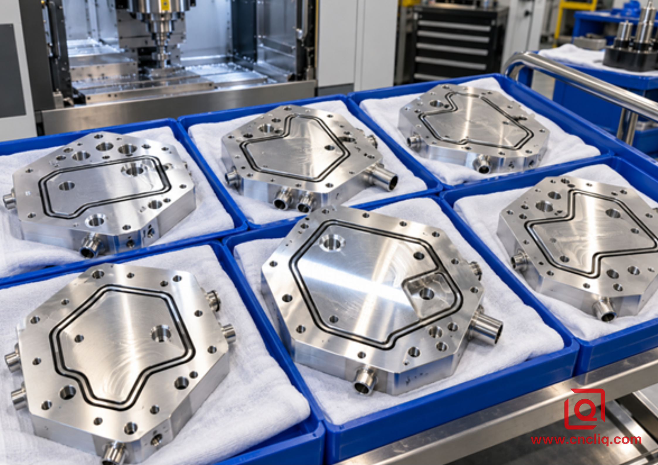
Anonymous composite case: aluminum vacuum-manifold baseplates
The following anonymized composite case is a realistic manufacturing scenario created to explain the process; it does not disclose a customer or claim a universal production result. A European automation integrator requested 6061-T651 vacuum-manifold baseplates for a semiconductor handling module. Each part had a broad mounting face, a serpentine O-ring groove, multiple cross-ports, and a cosmetic upper land. The controlled drawing target was 0.05 mm flatness across a 320 mm envelope and Ra 0.8 micrometers on the gasket land after machining, with no polishing permitted.
The early risk review identified 3 conflicts. Deep internal pockets removed material from one side, perimeter clamps could bend the thin remaining floor, and an aggressive final pass could generate enough heat to distort the inspection result. The process plan used matched blanks from the same material lot, balanced cleanup of both faces, staged roughing, a release-and-reseat step, and a dedicated low-force fixture. The finishing cutter used sharp aluminum geometry and a verified edge-height condition. Critical faces were finished after the machine, coolant, and workpiece reached a stable state.
Inspection followed the drawing rather than appearance. The quality team measured the gasket land texture at several locations across the lay, then mapped the mounting face on 3 defined supports after the part acclimatized. The control plan also required visual comparison under fixed lighting and protected handling in individual trays. If this were an RFQ, the supplier would need the 3D model, controlled 2D drawing, expected batch size, alloy and material form, flatness and roughness callouts, sealing requirements, prohibited processes, and inspection-report expectations.
For a verified product example involving precision-milled sealing faces, see Liqin’s precision aluminum manifold block. Another relevant production route is the precision aluminum light housing, where CNC-machined gasket surfaces and flatness control support enclosure sealing. These links show why finish specifications must be tied to the part’s real function.
What to Send for an Accurate Face-Milling Quote
A useful RFQ removes guessing. Send the native 3D model and a revision-controlled 2D drawing. Identify the alloy, temper, and preferred stock form; highlight critical-to-quality faces; state flatness, parallelism, roughness, lay, and cosmetic requirements; and define the inspection standard. Add annual volume, prototype quantity, delivery schedule, finishing route, packaging needs, and whether a full dimensional report or material certificate is required.
If “mirror finish” is important, include an approved sample or a measurable visual standard. State whether faint toolpath arcs are acceptable. Confirm whether the finish must come directly from face milling or whether fly cutting, lapping, polishing, or grinding may be proposed. A supplier can then separate the functional requirement from an unnecessarily expensive process assumption.
Need a manufacturability review? Send Liqin your CAD model, 2D drawing, target quantity, and critical surface callouts. Our engineering team can review material form, datum strategy, workholding risk, inspection method, and the finishing route before quotation. Use the contact form to start an RFQ discussion.
FAQ
1. Can face milling produce a true mirror finish on aluminum?
Face milling can produce a bright, highly reflective surface when the machine, cutter, insert height, chip load, and chip evacuation are well controlled, but “true mirror” is not a complete engineering specification. If an optical-grade reflection or extremely low roughness is required, a single-edge diamond process, lapping, or polishing may be more appropriate. Define Ra or Rz, lay, visual acceptance, flatness, and allowed secondary processes before selecting the method.
2. What surface roughness should I specify for a face-milled aluminum part?
Specify the roughness that the function needs, not the lowest number a supplier advertises. General as-machined faces can tolerate a coarser value than gasket lands, bearing interfaces, thermal contact pads, or cosmetic panels. Include the parameter, units, measurement direction, filter or cutoff when relevant, and measurement locations. If the surface is also flatness-critical, state that requirement separately because a low Ra value does not guarantee geometric flatness.
3. Why does an aluminum plate warp after it is unclamped?
The fixture may have forced a bowed blank flat, cutting may have released residual stress unevenly, or a temperature gradient may have existed between the top and bottom faces. When the clamp force disappears and the part cools, it moves toward a new free-state shape. Balanced material removal, staged roughing, re-seating, low-force support, stable temperature, and inspection after release are more reliable than simply adding a lighter final pass.
4. Is a larger face mill always better for flatness and finish?
No. A cutter wider than the part can reduce blend lines and finish a face in one sweep, but it also amplifies the effects of poor spindle tram, machine compliance, balance, and insert-height variation. A smaller cutter may fit the machine and reduce load, yet it creates overlapping passes that can show banding. Select diameter from part width, machine capability, spindle power, tool rigidity, and the required lay and cycle time.
5. How can a buyer verify a supplier’s mirror-finish and flatness capability?
Request a documented process and measurement plan, not only a photograph. The plan should identify material form, cutter type, runout control, fixture strategy, thermal condition, roughness instrument settings, flatness support and point map, and inspection-report format. For repeat orders, agree on an approved visual master and ask how tool life is monitored. A prototype or first-article run is the safest way to confirm that the quoted process matches the real drawing.
Summary
Mirror-like face milling and dependable aluminum flatness come from a controlled system: stable stock, balanced material removal, low-distortion workholding, correct machine geometry, sharp aluminum-specific tooling, measured runout, a consistent finishing cut, strong chip control, thermal stability, and separate verification of texture and form. Put measurable acceptance criteria on the drawing, share complete RFQ data, and qualify the process with first-article evidence before scaling production.
Contact Information
Company: Ningbo Liqin Industry Co., Ltd.Daily customer maintenance & after-sales support: service@shturl. zhuwanying@cncliq.com
New inquiry, quotation & order discussion: business@shturl. zhouli@chinaliqin.com
Hotline: +86 18757148656
Disclaimer
All technical articles, material specifications, machining recommendations, and surface treatment details published on this blog are for informational and reference purposes only. Please note that general blog insights do not replace signed technical agreements. Because custom parts vary by material heat numbers, machine calibrations, and specific tolerances, binding quality specs are governed solely by your approved CAD drawings, signed contracts, and formal quality plans.
All customer case studies featured on this blog have been thoroughly anonymized and sanitized. The performance metrics, manufacturing workflows, and imagery displayed serve solely to demonstrate our custom machining capabilities and do not represent a single universal standard for all orders.
Liqin Manufacturing Team
Built on 18 years of precision engineering experience, Ningbo Liqin Industry manufactures high-tolerance metal components for demanding global markets. We operate out of a 6,500 m2 production hub equipped with over 150 machines, running 4-axis and 5-axis CNC machining, mill-turn machining, cold extrusion, and pressure die casting under one roof. This setup allows us to manage projects seamlessly, taking parts from initial CAD concepts directly to finalized shipments.
We handle quality control with zero compromise. We treat tight tolerances with the engineering discipline they require. Backed by ISO 9001, ISO 13485, and IATF 16949 certifications, our QA engineers run strict IPQC, FQC, and OQC checks on every single production batch. From CMM dimensional mapping and optical profiling to hardness and salt-spray testing, we validate your critical specs upfront-so you receive drop-in ready components with zero assembly headaches or costly line stoppages. On top of manufacturing, you can rely on us for two-hour response times on new RFQs, direct support for prototype sampling, and smooth export shipping across Europe, North America, Asia, and Oceania.
Welcome your inquiries and samples. Visit our website or contact us directly for a competitive quote!
