 English




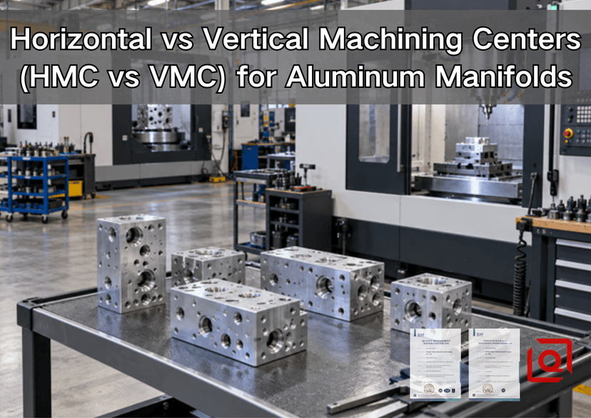
Are you still deciding whether an aluminum manifold should run on a horizontal machining center or a vertical machining center? The machine label alone will not protect a sealing face, keep intersecting ports aligned, or stop a burr from hiding deep inside a fluid passage. What matters is how the process holds the datum structure, reaches each face, removes chips, verifies the bore network, and scales from prototype to repeat orders. This guide explains that choice from the shop floor, in plain language, so design engineers and buyers can ask better questions before requesting a quotation.
The short answer is straightforward. A VMC is often the practical route for prototypes, small batches, broad flat manifolds, and parts dominated by one accessible face. An HMC becomes attractive when a block has important features on several sides, repeat demand supports dedicated fixturing, and fewer re-clamps can reduce variation between ports and sealing features. Neither layout is automatically more accurate. A capable process is the one that matches the part, controls its datums, and proves the result.
Quick Decision: HMC or VMC for an Aluminum Manifold?
Use the table as a first-pass filter, not as a substitute for drawing review.
|
Decision factor |
VMC is usually the stronger starting point |
HMC is usually the stronger starting point |
|
Part geometry |
Flat or plate-like body; most machining from the top and one secondary face |
Block-like body; ports, bores, and sealing features distributed across 3 or 4 faces |
|
Order pattern |
Prototype, engineering validation, high-mix/low-volume work |
Repeat batches where fixture and program preparation can be reused |
|
Workholding |
Simple vise, soft jaws, fixture plate, or a fourth-axis add-on |
Pallet, angle plate, or tombstone designed for multi-face access |
|
Chip behavior |
Manageable when pockets are open and coolant can flush them |
Helpful when deep cavities and cross-holes would otherwise retain chips |
|
Datum transfer |
Acceptable when features on different setups have moderate relationships |
Useful when cross-face position and orientation must be preserved from one clamping |
|
Change frequency |
Fast response to revisions and mixed part families |
Best when a stable design supports repeatable pallet loading |
|
Automation |
Possible, but often added to the basic process |
Commonly planned around pallet exchange and longer unattended cycles |
|
Best commercial fit |
Fast samples and flexible custom work |
Stable production and lower handling time per repeat part |
If the drawing sits near the middle, do not force a binary choice. A 4-axis VMC, a trunnion, or a 5-axis machine may provide the access needed without a full HMC production cell. Liqin's guide to multi-axis CNC milling for complex aluminum geometry explains that broader route.
What Changes When the Spindle Turns Sideways?
A vertical machining center points the spindle down toward a horizontal table. Loading is intuitive: the operator places the billet or pre-machined blank on the table, sets the primary datum, and can see the cutting zone clearly. For a manifold with a large top valve pattern, shallow pockets, or a wide sealing face, that access is valuable.
A horizontal machining center points the spindle toward a generally vertical workholding face. The pallet or rotary axis presents another side of the block to the spindle. This does not create quality by itself. It changes the process opportunities: several faces may be cut without manual re-clamping, chips tend to fall away from vertical faces, and a second pallet may be loaded while the other one is in the enclosure.
For aluminum manifolds, those differences reach beyond cycle time. Internal passages are often made by drilling from more than one side until bores intersect. Threaded cartridge cavities may reference one datum while an O-ring groove references another. Every time a part is removed, cleaned, turned, and located again, the process creates another opportunity for a chip under a locator, jaw pressure change, or datum misunderstanding. A well-designed HMC setup can reduce those transfers. A well-designed VMC process can still succeed by using qualified soft jaws, probing, controlled cleaning, and planned in-process inspection.
The 7 Manufacturing Issues That Should Drive the Choice
1. Feature Distribution Matters More Than the Outside Shape
Start by coloring the drawing by machining direction. If nearly all critical features point in one direction, a VMC is difficult to beat. If functional ports point in 3 or 4 directions and their locations relate tightly to the same datum reference frame, an HMC or multi-axis route deserves serious consideration.
Do not count faces alone. Count critical relationships. A cosmetic mounting hole on a side face is different from a cross-bore that must meet a valve cavity without leaving a partial intersection. The process engineer should identify which dimensions can tolerate a separate setup and which should stay in one clamping.
This is where GD&T improves the conversation. ASME Y14.5-2018 establishes a shared language for datums, position, orientation, form, and related requirements. ISO 1101:2017 provides the ISO framework for geometrical tolerancing. A clear datum scheme lets the supplier design the process around function instead of guessing which edge or surface is important.
2. Re-Clamping Is a Risk Chain, Not Just Extra Labor
Imagine a rectangular manifold machined on a 3-axis VMC. Setup 1 establishes the primary mounting face and top cavities. Setup 2 locates the part in soft jaws to drill the front ports. Setup 3 turns it again for side ports. Setup 4 finishes a rear sealing face. Each setup can be stable, but the cross-face result depends on every locator, stop, jaw, cleaning step, and offset.
On an HMC, the same block may remain on one fixture while a rotary pallet indexes the required faces. The relationship between those faces then depends more heavily on machine geometry, rotary positioning, fixture stiffness, tool condition, and probing strategy. That is usually a shorter error chain, but it still needs verification.
Ask suppliers to explain the setup map. A credible answer should identify the primary, secondary, and tertiary datums; which features are completed in the same clamping; where stock is left for finishing; and how the first article is checked. If the answer is only “we use a 5-axis” or “we use an HMC,” the important process questions remain unanswered.
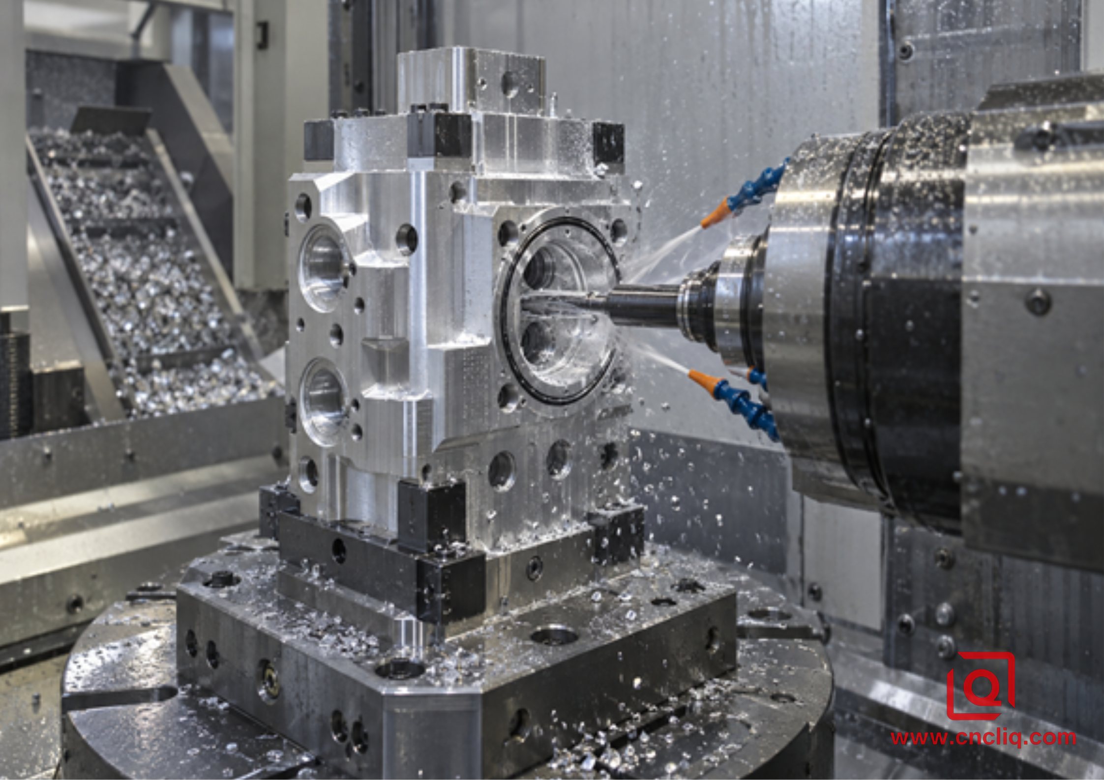
Horizontal machining: multi-face access and gravity-assisted chip flow around an aluminum manifold.
3. Chip Evacuation Becomes a Quality Issue Inside Manifolds
Aluminum can produce a large volume of chips quickly. In a VMC, chips can settle in open pockets and blind holes because gravity pulls them toward the workpiece. Coolant direction, toolpath design, peck strategy, and deliberate chip-clearing moves become important. Recut chips can mark sealing surfaces, encourage built-up edge, or pack into a deep bore.
On an HMC, machined faces are often vertical, so gravity assists chip fall. That is useful around deep cavities and multi-directional ports. Yet an HMC does not guarantee a clean internal circuit. Burrs can remain where 2 drilled passages break into each other, and a long curled chip can lodge behind a shoulder. The route still needs cross-hole deburring, washing, drying, and inspection appropriate to the drawing and end use.
For difficult small passages or deep threaded ports, review the site's related guidance on deep-hole drilling and rigid tapping in aluminum. It addresses the same practical failure modes without turning this comparison into another drilling article.
4. Fixture Stiffness Must Not Become Part Distortion
Manifold billets look solid, but deep pockets and intersecting cavities can leave thin webs between passages. Excess jaw pressure may elastically distort the blank during finishing. When the clamps release, a sealing face or bore relationship can move. Too little force creates a different problem: chatter, micro-slip, or inconsistent location.
A VMC often supports a broad, flat part directly under the cutting load. That can be helpful for plate-like manifolds. An HMC fixture must resist cutting loads and the moment created by a vertically mounted part. Tombstone access is excellent only when clamps, supports, and tools can reach the required faces without compromising rigidity.
The correct fixture therefore follows the part. Use stable datum pads, keep clamp forces away from flexible walls where possible, and support the cutting load close to the feature. When a design removes a large share of the original billet, roughing and finishing may need to be separated so the part can relax before the final datum and sealing surfaces are completed. Liqin's article on controlling deformation in aluminum CNC machining expands on that subject.
5. Surface Finish and Flatness Depend on the Whole System
Buyers sometimes assume an HMC produces a better surface than a VMC. That is too simple. Surface finish depends on the machine's condition, spindle and toolholder, cutter geometry, runout, workholding stiffness, feed strategy, coolant, and material condition. Either machine type can produce a functional sealing face when the process is capable.
Orientation still affects access. A broad face is easy to support and sweep on a VMC. An HMC can finish several valve and port faces without breaking the datum chain. The right question is not “Which machine is more precise?” It is “Which routing gives this drawing the shortest, most controllable chain from datum creation to final verification?”
Never specify a very fine finish everywhere by habit. Separate hydraulic or pneumatic sealing faces, gasket faces, O-ring grooves, valve bores, mounting pads, and cosmetic faces. Put surface texture and flatness requirements where function needs them. Excessive blanket tolerances increase inspection and finishing effort without improving assembly.
6. Volume Changes the Economics
A VMC often reaches first chips quickly. Standard vises, modular plates, and accessible setups make it suitable for prototype manifolds, design revisions, and small orders. That flexibility has commercial value because engineers can learn from real parts before committing to dedicated fixtures.
An HMC generally asks for more process planning. The pallet arrangement, tool list, collision clearance, fixture balance, and sequence across multiple faces must be settled. Once proven, that work can support repeat batches with less manual handling between operations. The business case improves when the design is stable and the same setup is used again.
Do not choose a route from annual quantity alone. Batch size, release frequency, revision risk, tool life, inspection load, secondary cleaning, and required delivery cadence all matter. A yearly demand of 1,000 parts released as 20 engineering revisions is a different job from 1,000 identical parts released on a steady schedule.
7. Inspection Must Follow Function, Not the Machine Tool
In-process probing can confirm that stock is present, locate a blank, or check selected features before unclamping. It is useful process control, but it does not replace an independent inspection plan. For manifolds, inspection may include bore diameter, true position, perpendicularity, sealing-face flatness, thread gaging, edge condition, cleanliness, and leak or pressure testing when the approved quality plan requires it.
Dimensional results are temperature-sensitive. ISO 1:2022 defines the standard reference temperature used for dimensional and geometrical properties. A serious measurement plan states how parts are stabilized and how calibrated equipment is used. For more detail, see Liqin's guide to CMM inspection for custom aluminum machining.
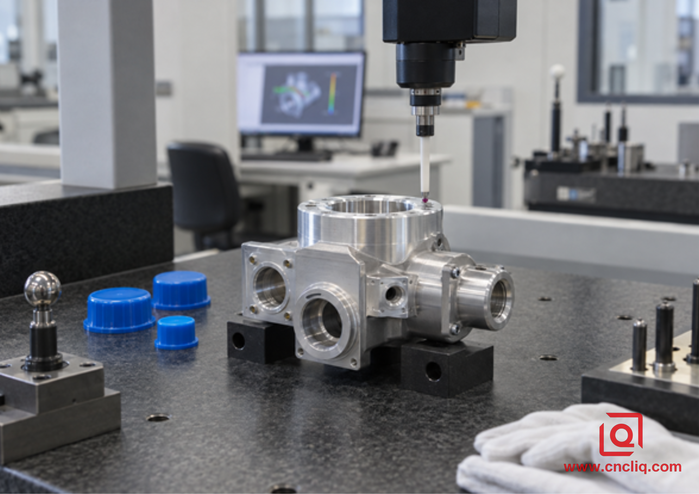
Independent dimensional verification of a finished aluminum manifold in the metrology room.
A Practical Process Route for Each Machine Type
VMC Route for Prototype or High-Mix Manifolds
1. Review the 3D model and 2D drawing together; identify functional datums, plugged drill intersections, critical threads, sealing faces, and inspection access.
2. Prepare the billet and establish the primary datum face with enough stock left for controlled finishing.
3. Machine the dominant face in a stable vise or fixture plate. Use probing where appropriate to locate stock and protect wall allowance.
4. Transfer the part into qualified soft jaws or a dedicated secondary fixture for side ports. Clean every locator before seating the part.
5. Re-establish the datum system, machine secondary faces, and verify cross-face relationships before the last setup is released.
6. Deburr accessible edges, treat cross-hole intersections with a validated method, wash the internal network, and dry it completely.
7. Inspect critical geometry, threads, and sealing features; perform functional tests only to the agreed drawing or quality plan.
This route is transparent and flexible. It also makes setup discipline visible. If the part is revised, a modular fixture may be adjusted without replacing an entire pallet system.
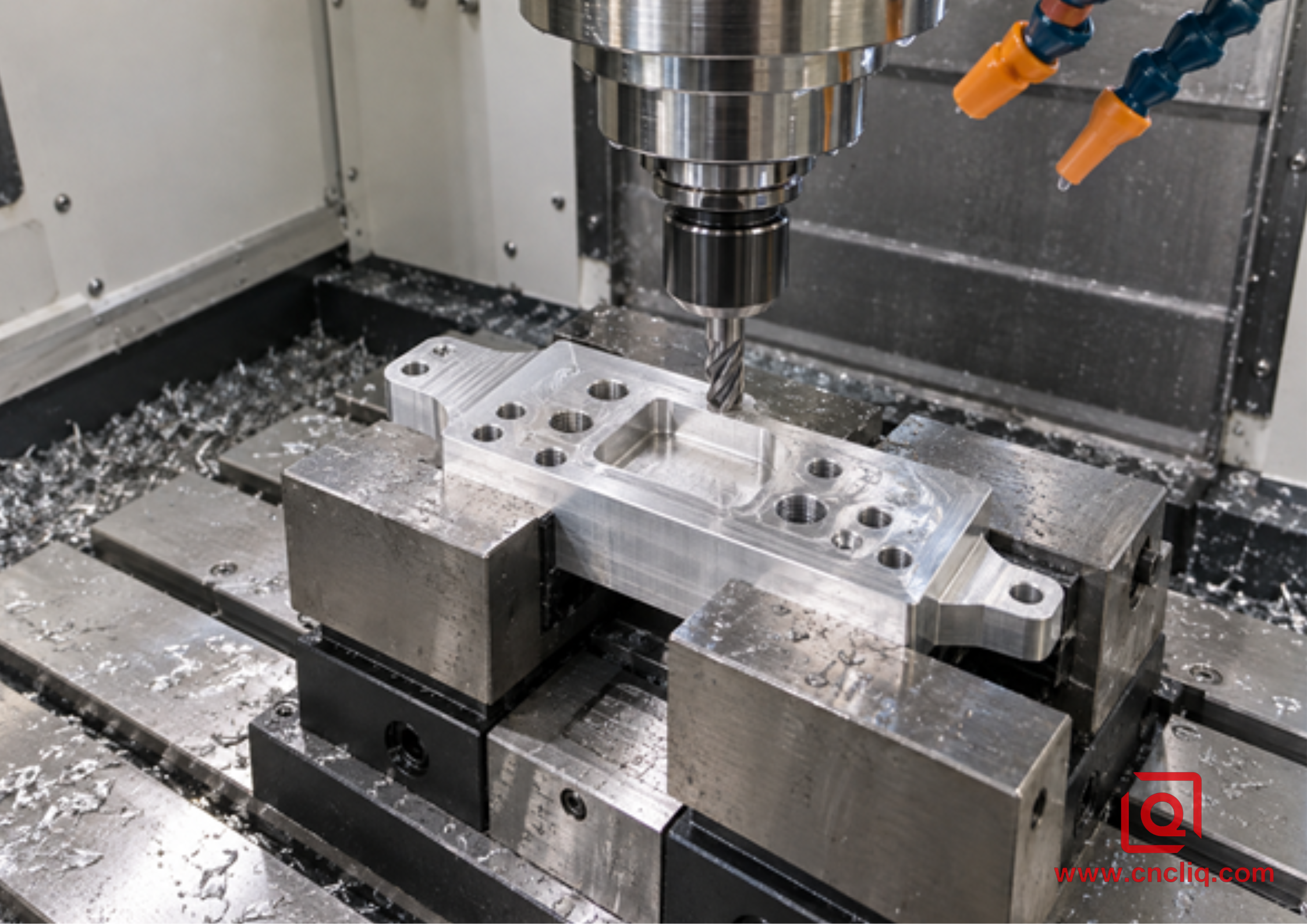
Vertical machining: accessible fixturing for a low-volume aluminum manifold prototype.
HMC Route for Stable Multi-Face Production
1. Build the fixture around the drawing's datum reference frame and confirm tool access to all required faces.
2. Plan the sequence so roughing loads, deep drilling, and finish operations do not destabilize a completed sealing feature.
3. Load the blank on the pallet or tombstone with controlled torque or hydraulic pressure; verify seating before cycle start.
4. Establish the work coordinate system, then index the pallet to machine related faces without manual re-clamping.
5. Use tools and coolant delivery suited to deep bores, counterbores, threads, and cross-hole intersections; monitor chip transport throughout the cycle.
6. Probe selected features in process where it reduces risk, then complete independent dimensional and functional verification after cleaning.
7. Record tool-life limits, offset rules, fixture checks, and inspection frequency so repeat batches use the same controlled method.
The HMC route earns its place when it removes handling and preserves cross-face relationships. It is not automatically the cheapest route for an early prototype, and it should not be quoted as a production advantage until fixture, inspection, and cleaning requirements are included.
Anonymous Case: Choosing a Hybrid Route for a Compact Pneumatic Manifold
An equipment builder asked for a compact aluminum pneumatic manifold used in an automated assembly module. The sanitized design contained a broad mounting face, 3 valve pockets on top, ports on 2 side faces, and several intersecting passages. The first release was a small validation batch, while the forecast suggested repeat demand after field testing. The customer cared most about port alignment, sealing-face stability, clean internal passages, and a smooth transition from samples to production.
The engineering review did not force the part directly onto an HMC. For the first batch, a VMC with modular soft jaws offered faster revision response. The main face and valve pockets were completed first; 2 controlled secondary orientations handled the side ports. The inspection plan tied the cross-face features back to the declared datums, and the cleaning plan called out the internal passage network separately from exterior washing.
After the drawing stabilized, the repeat route moved to a palletized multi-face process. A dedicated fixture held the same datum structure and reduced manual re-clamping. The change was justified by repeatability and handling reduction, not by a claim that one machine was universally “more precise.” The case illustrates a useful purchasing principle: prototype on the process that supports learning, then industrialize on the process that supports stable demand.
Liqin's existing custom hydraulic manifold product page shows the related custom-part scope, drawing formats, material options, process options, and inspection resources that can be discussed during an RFQ. The case above is an anonymized illustrative scenario, not a disclosure of any named customer's drawing or operating data.
DFM Checklist Before You Request a Quote
Send more than a 3D model if you want a meaningful HMC vs VMC recommendation. Include:
• A revision-controlled 3D CAD file and a matching 2D drawing.
• Material grade and temper, not just “aluminum.” If selection is open, the comparison of 6061 and 7075 aluminum for OEM machining can frame the discussion.
• Annual quantity, batch quantity, prototype quantity, and expected design-freeze date.
• The primary, secondary, and tertiary datums, plus the GD&T standard used on the drawing.
• Critical-to-function bores, threads, sealing faces, O-ring grooves, and cross-port relationships.
• Pressure, leak, cleanliness, traceability, and documentation requirements that are actually part of acceptance.
• Surface treatment, masking zones, plugged ports, and whether dimensions apply before or after finishing.
• Mating components or interface drawings when stack-up affects the manifold.
• Packaging requirements that protect clean ports and finished sealing faces.
These inputs let the supplier compare complete routes instead of comparing hourly machine rates. They also help identify whether a custom CNC machining service should quote a flexible VMC process, a palletized HMC process, or a multi-axis hybrid.
How Buyers Should Compare HMC and VMC Quotations
Two quotes can use the same alloy and still represent very different levels of control. Ask the supplier to separate assumptions that materially affect price and risk.
|
Quote question |
Why it matters |
|
How many setups are planned? |
Reveals handling, datum-transfer, and inspection risk |
|
Which features stay in one clamping? |
Shows whether critical cross-face relationships are protected |
|
Is fixture cost one-time or recurring? |
Prevents a misleading part-price comparison |
|
What is included in deburring and internal cleaning? |
A manifold can be dimensionally correct and still fail from trapped debris |
|
Which features receive full inspection, sampling, or capability monitoring? |
Aligns the quality plan with functional risk |
|
Are leak or pressure tests included? |
Avoids assuming a functional test is part of standard dimensional inspection |
|
What changes after prototype approval? |
Clarifies whether the production route, fixture, and validation plan will change |
|
How are design revisions controlled? |
Reduces the risk of machining an obsolete port map or tolerance set |
The lowest machining price is not necessarily the lowest landed risk. A route with fewer setups may cost more to prepare but reduce handling and simplify repeat production. A VMC route may be the smarter purchase when revision flexibility matters more than steady-state output. Ask for the reasoning, then compare it with your program stage.
When a 4-Axis or 5-Axis VMC Is the Better Middle Ground
The real shop-floor decision is not always HMC versus basic 3-axis VMC. A fourth-axis indexer can expose several sides of a manifold while keeping the familiar vertical platform. A 5-axis machine can orient angled ports and reduce special fixtures, especially for complex geometry or smaller lots. These options can shorten the datum chain without requiring a dedicated HMC cell.
They also introduce new constraints: rotary-axis capacity, tool reach, collision clearance, fixture access, postprocessor reliability, and the need to verify rotated workplanes. The best choice remains part-specific. If a supplier proposes 5-axis machining, ask which functional relationships it protects and which secondary operations still remain.
FAQ
1. Is an HMC always better for aluminum hydraulic manifolds?
No. An HMC is often effective for block-shaped manifolds with important features on several faces and repeat production demand, because it can index the part and reduce manual re-clamping. A VMC may be faster and more economical for prototypes, broad flat manifolds, frequent revisions, or parts dominated by one machining direction. The drawing, datum structure, batch pattern, cleaning plan, and inspection plan should decide the route.
2. Can a VMC hold tight positional relationships between ports on different faces?
Yes, provided the process controls each transfer. Qualified soft jaws or fixtures, clean locators, probing, stable datums, calibrated equipment, and an inspection plan can produce reliable cross-face geometry. The risk increases as critical features are spread across more setups, so the supplier should show how datum transfer is controlled and whether a rotary or multi-axis option would shorten the chain.
3. Does better HMC chip evacuation eliminate cross-hole burrs?
No. Gravity can help chips leave a vertical cutting face, but burrs may still form where drilled passages intersect or where a tool exits into an internal cavity. The process needs a deliberate deburring method, internal washing, drying, and verification appropriate to passage size and end-use risk. Chip evacuation during cutting and internal cleanliness after cutting are related but separate controls.
4. What files and information are needed for an accurate aluminum manifold quote?
Provide a revision-controlled 3D CAD model, a matching 2D drawing, alloy and temper, quantity and release pattern, functional datums, critical tolerances, surface finish, surface treatment, thread and port standards, cleanliness requirements, and any leak or pressure-test acceptance criteria. Also identify which requirements apply before and after coating. This information lets the supplier compare VMC, HMC, and multi-axis routes on the same scope.
5. How should I verify that a supplier's machine choice is reliable?
Ask for a setup map, datum strategy, fixture concept, tool-access review, deburring and cleaning flow, first-article plan, and inspection method for critical features. Confirm whether the production route matches the sample route and how tool wear or offsets are controlled across a batch. A machine list is useful, but evidence of a controlled process is more important than the letters HMC or VMC.
Summary
Choose a VMC when flexibility, fast setup, broad top-face access, and prototype learning lead the project; choose an HMC when stable repeat demand, multi-face machining, chip flow, and fewer re-clamps create a better-controlled route. For aluminum manifolds, the winning process protects the datum structure, manages cross-hole burrs and internal cleanliness, verifies functional geometry, and makes the transition from sample to production explicit. Send your drawing, 3D model, quantities, and acceptance requirements to Liqin for a process-specific DFM review and quotation rather than a machine-name guess.
Contact Information
Company: Ningbo Liqin Industry Co., Ltd.
Daily customer maintenance & after-sales support:service@shturl. zhuwanying@cncliq.com
New inquiry, quotation & order discussion:business@shturl. zhouli@chinaliqin.com
Hotline: +86 18757148656
Disclaimer
All technical articles, material specifications, machining recommendations, and surface treatment details published on this blog are for informational and reference purposes only. Please note that general blog insights do not replace signed technical agreements. Because custom parts vary by material heat numbers, machine calibrations, and specific tolerances, binding quality specs are governed solely by your approved CAD drawings, signed contracts, and formal quality plans.
All customer case studies featured on this blog have been thoroughly anonymized and sanitized. The performance metrics, manufacturing workflows, and imagery displayed serve solely to demonstrate our custom machining capabilities and do not represent a single universal standard for all orders.
Liqin Manufacturing Team
Built on 18 years of precision engineering experience, Ningbo Liqin Industry manufactures high-tolerance metal components for demanding global markets. We operate out of a 6,500 m² production hub equipped with over 150 machines, running 4-axis and 5-axis CNC machining, mill-turn machining, cold extrusion, and pressure die casting under one roof. This setup allows us to manage projects seamlessly, taking parts from initial CAD concepts directly to finalized shipments.
We handle quality control with zero compromise. We treat tight tolerances with the engineering discipline they require. Backed by ISO 9001, ISO 13485, and IATF 16949 certifications, our QA engineers run strict IPQC, FQC, and OQC checks on every single production batch. From CMM dimensional mapping and optical profiling to hardness and salt-spray testing, we validate your critical specs upfront—so you receive drop-in ready components with zero assembly headaches or costly line stoppages. On top of manufacturing, you can rely on us for two-hour response times on new RFQs, direct support for prototype sampling, and smooth export shipping across Europe, North America, Asia, and Oceania.
Welcome your inquiries and samples. Visit our website or contact us directly for a competitive quote!
