 English




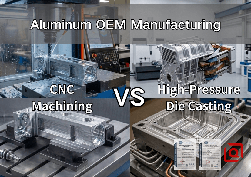
When an engineering drawing lands on our machining floor, the question isn’t simply “can we make this?” It’s always “how will this part behave when tool pressure hits it, or when molten alloy freezes inside the mold under 800 bar of pressure?”
Procurement always chases the same checklist: zero voids, crisp chamfers, dead-on true position, and rock-bottom piece costs. Out on the floor, we know better—picking between 5-axis CNC machining and high-pressure die casting (HPDC) is never a coin flip. Call it wrong, and you either torch your tooling budget on early revisions or burn thousands of spindle hours chewing raw billet when near-net casting drops cycle times by 65%. We dialed in this matrix from hard-run production across 3 tough sectors: Medical Imaging & Surgical Devices, Automotive Powertrain & Sensor Housings, and Precision Industrial Automation & Robotics.
The Engineering & Production Reality: Head-to-Head Comparison
Before case studies, let's establish the shop-floor baseline. We run 3-axis to 5-axis CNC machining centers alongside cold-chamber die casting cells from 280-ton to 1,600-ton clamping force. Here is how both processes compare:
| Key Evaluation Metric | High-Precision CNC Machining | High-Pressure Die Casting (HPDC) | Hybrid Approach (Cast + Post-CNC) |
| Typical Material Grades | AL 6061-T6, AL 7075-T651, AL 5052-H32, AL 2024 | A380, ADC12, AlSi10Mg, A383 | A380 / ADC12 with 6061 billet fixtures |
| Machining / Part Tolerance | ISO 2768-m to ±0.005 mm (Linear), GD&T True Position Ø0.01 mm | Standard NADCA Grade: ±0.05 mm to ±0.15 mm | Cast body ±0.1 mm; CNC Critical bores ±0.008 mm |
| Surface Finish (As-formed) | Ra 0.8 µm to Ra 0.4 µm (Surface grinding down to Ra 0.1 µm) | Ra 1.6 µm to Ra 3.2 µm (Mold cavity polish dependent) | Mating surfaces fly-cut to Ra 0.4 µm; As-cast Ra 2.0 µm |
| Tooling & Setup Investment | Zero hard mold tooling ($0 NRE); Soft jaws and custom fixtures | High NRE ($8,000 to $45,000+ for H13 hardened steel dies) | Initial die investment + Modular CNC secondary clamping |
| Economic Batch Size (MOQ) | 1 pc to 1,500 pcs (High mix, low-to-mid volume) | 3,000 pcs to 200,000+ pcs/year | 1,500 pcs to 50,000+ pcs/year |
| Internal Structural Integrity | 100% dense wrought billet; zero gas porosity or inclusions | Sub-surface gas porosity risk; requires vacuum venting | Critical sealing tracks pocket-milled past skin layer |
| Surface Treatment Match | Class II & Class III Hard Anodize (MIL-A-8625), Chem-film (MIL-DTL-5541) | E-coating, Powder coating, Chromate; Anodizing yields blotchiness | Selective masking: Chromate overall, diamond-turn faces |
1. Medical Imaging & Surgical Assemblies: Structural Rigidity Without Sub-Surface Flaws
In medical hardware, component reliability is absolute. We frequently produce robotic arm positioning links, endoscopic camera chassis, and diagnostic fluid manifolds.
The Real Problem on the Bench
A client approached us with an articulated optical bracket mounted on a portable surgical laser rig. The part demanded an internal hydraulic cooling channel running alongside sensitive fiber-optic paths. They originally intended to die-cast the part in ADC12 alloy to hit a target price under $15 per unit for an annual run of 2,200 units.
When you cast thin-walled components with intricate cross-drilled passages, turbulent metal filling traps micro-bubbles. During post-machining of the O-ring gland sealing faces, cutters sliced straight into subsurface gas porosity. Under a helium leak check at 3.5 bar, cast samples exhibited micro-seepage through the wall sections.
The Machining Floor Execution
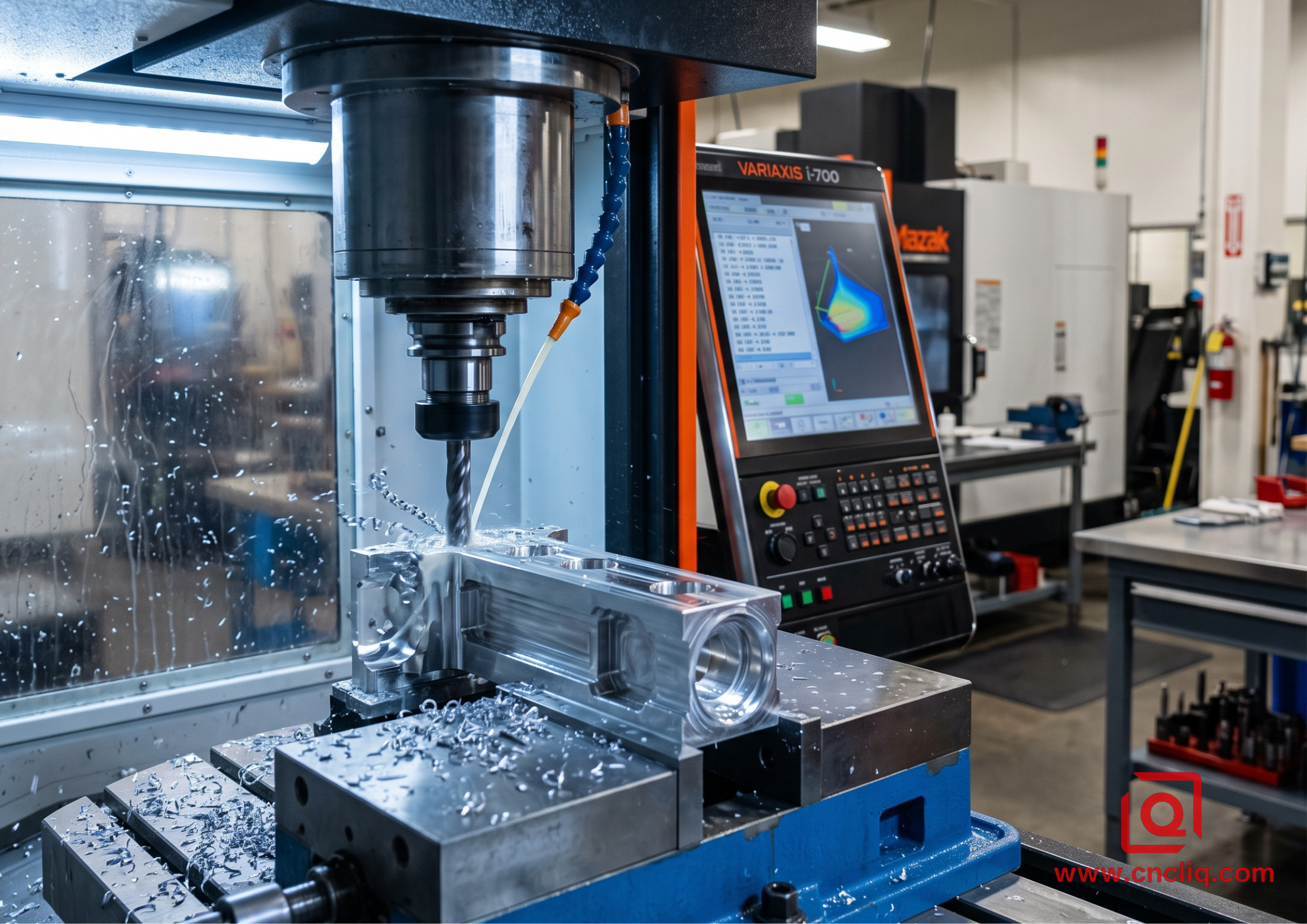
We switched the entire project to wrought AL 6061-T6 billet on a 5-axis machining center.
-
Roughing stock: We locked the extruded 6061-T6 stock into a 5-axis self-centering vise and let a 16 mm 3-flute carbide mill rip out the bulk material. Pushing 9,500 RPM at a 4,200 mm/min feed rate, we left a clean 0.3 mm skin across all datums for finishing.
- Stress-relief resting: Heavy roughing chews away 70% of the stock, locking in massive internal stresses. We backed off the clamps, let the part sit and normalize, then re-torqued evenly to 45 Nm.
- Finish milling & bore interpolation: We whipped the bearing journals to Ø28.000 mm (+0.008/-0.000 mm) using helical toolpaths—holding a strict ISO 286-2 (H7) fit.
- Anodizing performance: We dropped raw 6061-T6 straight into the bath for a MIL-A-8625 Type III hardcoat, pulling a dense 45 µm skin right at 60 HRC. That case easily takes a beating from 134°C autoclave steam runs—zero blistering, zero flaking off down the road.
The shop call: If your medical housing demands zero trapped gas pockets, true hermetic seals, and bulletproof hard anodizing for bio-washdown, grab a 5-axis mill and cut from wrought billet. It beats die casting hands down—even when facing an 18-minute cycle against 45 seconds on a press.
2. Automotive Sensor Housings & Electric Actuator Covers: The High-Volume Cost Wall
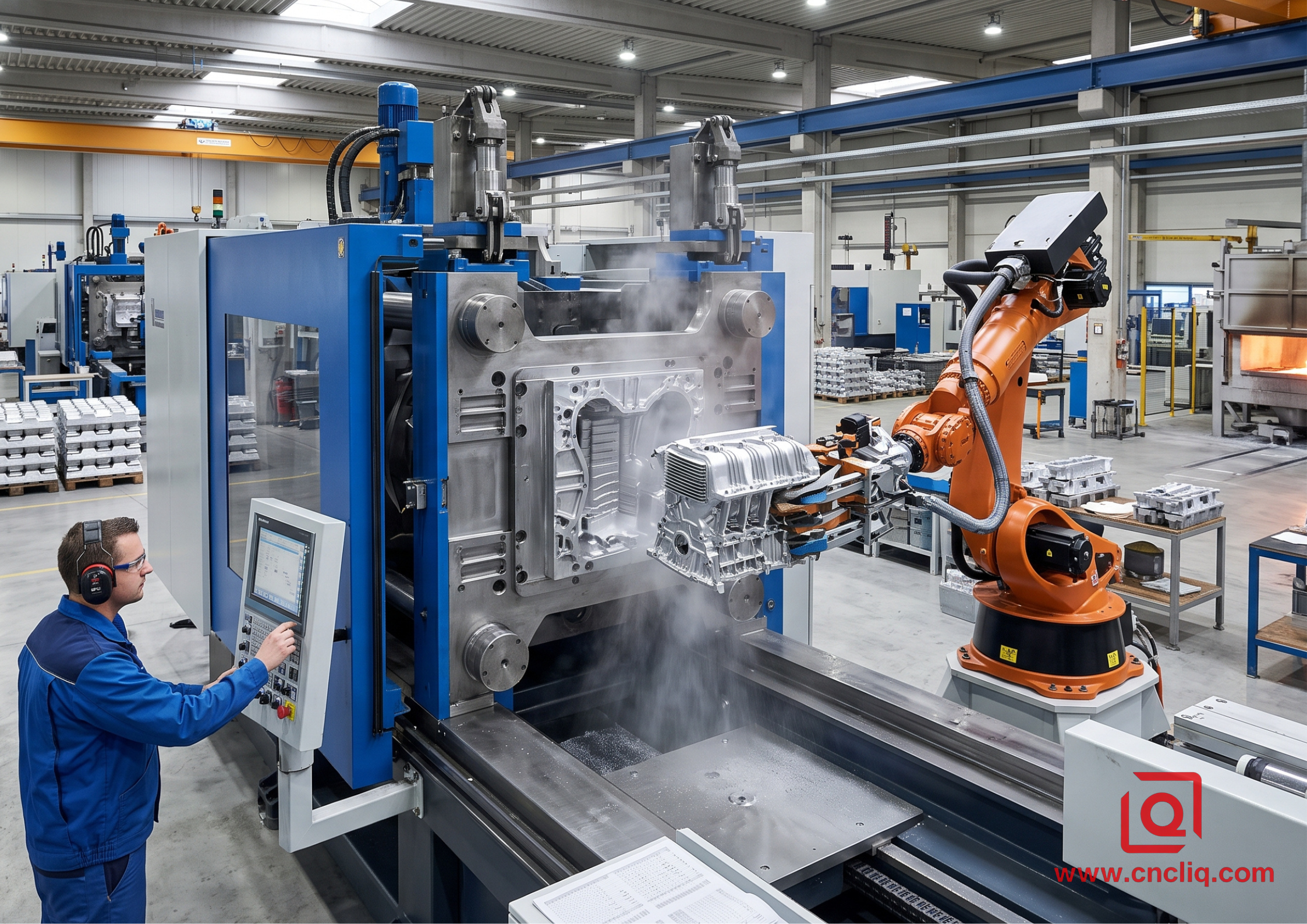
Automotive tier suppliers operate under relentless cost pressures and strict IATF 16949 quality gates. When quantities surge past 15,000 units per quarter, machining solid aluminum bar is burning money.
The Shop-Floor Challenge
An automotive client required an IP67-rated electronic throttle actuator housing. The geometry featured thin cooling fins (1.2 mm thick), complex outer mounting brackets, deep draft pockets, and four threaded M4 inserts.
Machining this housing from a 120 mm × 100 mm × 65 mm block of 6061 alloy generated an 82% scrap chip ratio. Cycle time sat at 14 minutes and 30 seconds per piece. With a targeted volume of 60,000 pieces per year, machine capacity bottlenecks became a fatal hurdle.
The Tooling & Casting Solution
We cut a 2-cavity mold out of H13 tool steel—heat-treated straight to 48 HRC—and bumped production onto an 800-ton cold-chamber press, shooting standard A380 alloy under high pressure.
-
Shot Parameters: Molten A380 was injected at 660°C under 750 bar injection pressure, hitting a plunge velocity of 3.8 m/s at the gate to ensure full fin filling without cold-shuts.
-
Secondary Precision Machining: The cast body formed the thin 1.2 mm heat dissipation fins and mounting ribs directly in a 32-second casting cycle. We transferred the part onto a twin-pallet 4-axis horizontal machining center (HMC).
- Targeted Operations: We only kissed the money datums: fly-cutting the outer perimeter seal track down to Ra 0.8 µm, whirling 4 M4 holes at 6,000 RPM with an M4×0.7 carbide thread mill, and reaming the sensor dowel locations tight to Ø6.000 mm ±0.006 mm.
- Corrosion Protection: We ran batches through an automated trivalent chromate line under MIL-DTL-5541 Type II Class 1A—parts cleared 168 hours of ASTM B117 salt spray without a speck of pitting.
The payoff: Piece costs dropped off a cliff by 61%. That $18,500 tooling check paid for itself inside the first 6,000 hits, pocketing huge margins across the entire 120,000-unit run.
3. Industrial Automation & Pneumatics: Dynamic Robot Grippers and Valve Manifolds
Industrial automation demands rapid acceleration, high payload-to-weight ratios, and repeatable dimensional stability under high cycle frequencies.
The Application Split
In pneumatic valve blocks and robotic end-of-arm tooling (EOAT), we deploy both processes based on functional demands:
Case A: 5-Port Pneumatic Directional Control Valve Block
-
Material: 6061-T651 cold-drawn manifold bar.
-
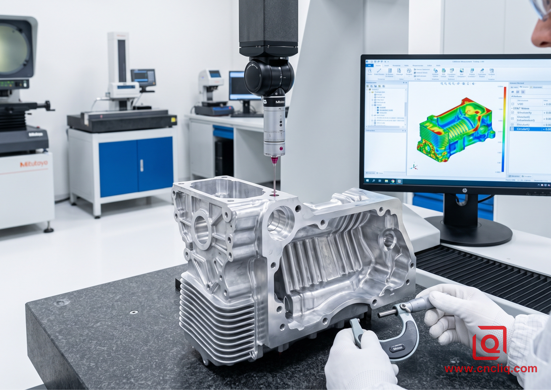
Why CNC over Casting: The valve spool bore has a cylindrical runout requirement of under 0.003 mm and a surface finish of Ra 0.2 µm. Casting A380 introduces abrasive silicon crystals (8.5% to 10.5% Si content) that cause micro-scratches on dynamic polyurethane seals, destroying pneumatic sealing within 200,000 cycles.
-
Machining Method: Deep-hole gun drilling of the central 180 mm spool passage, followed by rigid diamond reaming and roller burnishing to hit true roundness within 0.0025 mm.
Case B: Collaborative Robot (Cobot) Outer Joint Enclosure
-
Material: ADC12 Die-Cast Aluminum.
-
Why Casting over CNC: The joint housing has curved ergonomic safety contours and internal wire harness routing clips that would require a 5-axis ball-nose surfacing tool running for 40 minutes per part.
-
Process: Cast near-net shape in 40 seconds; secondary 3-axis CNC facing cuts the split-line mating surface to eliminate light gaps, achieving an IP65 ingress protection rating with a molded silicone gasket.
The 4-Step Practical Decision Roadmap
Before issuing your next Request for Quote (RFQ), run your aluminum OEM component through this shop-floor checklist:
[ Step 1: Evaluate Annual Production Volume ]
   ├── < 1,500 pcs/year ───────────────────────► Full CNC Machining (Avoid Tooling Costs)
   └── > 3,000 pcs/year ───────────────────────► Proceed to Step 2

[ Step 2: Inspect Wall Thickness & Geometry ]
   ├── Solid blocks, deep internal cross-holes ─► Full CNC Machining
   └── Thin walls (1.0-3.0 mm), complex ribs ──► High-Pressure Die Casting

[ Step 3: Check Tightest Dimensional Tolerance ]
   ├── Position < ±0.01 mm, Bores < H7 ────────► Hybrid (Die Cast + Secondary CNC)
   └── Standard external fits > ±0.10 mm ──────► Direct Die Casting As-Cast

[ Step 4: Define Surface Treatment ]
   ├── Decorative Color / Mil-Spec Hard Anodize► CNC Wrought Billet (6061 / 7075)
   └── E-Coat / Powder Coat / Chromate ────────► Die Cast Alloy (A380 / ADC12)
FAQs
Q1: Why does color anodizing look like a blotchy, muddy mess on cast alloys like A380 or ADC12?
A: Look at the melt chemistry. Foundry blends load up on silicon—we see 8.5% to 11.5% Si in shop-grade ADC12 or A380—purely to push molten metal through deep, knife-edge ribs without freezing off. Dunk that raw casting into an anodizing tank under MIL-A-8625, and free silicon shreds your barrier layer—you get slapped with chalky gray blotches and nasty flow marks every time. When your customer's print calls for show-car color matching (Type II) or true-spec Type III hardcoat, do yourself a favor: kill the die tooling and hog it straight out of 6061-T6 or 7075-T651 wrought stock. Stuck with die castings? Stay out of the color lines—seal them via automated MIL-DTL-5541 trivalent chromate or lay down uniform E-coat to lock in salt-spray resistance without the surface drama.
Q2: How can we eliminate micro-porosity issues when pressure-testing die-cast aluminum housings?
A: Subsurface gas and shrinkage porosity are natural physics challenges in high-pressure casting. To ensure pressure tightness (such as 3 to 5 bar pneumatic test specs):
- Tooling Design: We drop massive vacuum blocks and chill vents right into the mold parting line, pulling 90%+ of trapped pocket air out in milliseconds before the shot solidifies.
- DFM Machining Rules: Don't get greedy on the mill. Cap post-cast CNC cleanups at 0.5 mm depth—if you blow past that dense 1.0 mm outer cast chill skin, you will expose nasty internal micro-porosity every time.
- Vacuum Impregnation: For leak-tight hydraulic blocks or fuel rails, we dunk finished castings into an anaerobic resin autoclave under MIL-I-17563C, locking up micro-voids for good without touching your finished tolerances.
Q3: When transitioning from CNC prototypes to high-volume die casting, what CAD design changes are mandatory?
A: Never shoot a 3D model meant for a milling center straight into a casting press—you will ruin the tool. Before we spark the H13 die, make these 3 shop-floor DFM fixes:
- Throw in Draft Angles: Add at least 1.0° to 2.0° draft on outside ribs and pull cores. Skip this, and parts will drag, gall, and seize during ejection.
- Keep Walls Even: Core out beefy boss sections down to 1.5 mm to 3.0 mm uniform nominal walls. Thick globs of aluminum stay hot too long and suck in massive shrinkage sinks.
- Blend Sharp Corners: Kill every sharp 90° inside edge. Radii them out to at least R1.0 mm to R1.5 mm so hot metal glides around bends without spiking stress risers in the tool steel.
Q4: How many shots can you realistically squeeze out of an H13 die before it dies, and what does your maintenance loop look like?
A: Build your tool right with vacuum-quenched H13 or DIEVAR (dialed into 46 to 50 HRC), and you will comfortably pull 80,000 to 120,000 shots in aluminum before fatigue kills the cavity. The real secret? Keeping thermal cycling under control so heat stress doesn't tear the steel apart. On our shop floor, we pull molds down every 10,000 hits like clockwork. Our toolmakers tear down the whole mold block, sonic-bath away any welded aluminum pickup, and scope out fine thermal check-lines under dye penetrant. Then, we bake the inserts in a draw furnace for stress-relief—milking every last hit out of the tool steel.
Q5: Can you hit dead-nuts bearing journals (like ISO H7 or ±0.008 mm) right out of the casting die without secondary milling?
A: Don't even try. Real-world NADCA casting limits hover between ±0.05 mm and ±0.15 mm because you are fighting molten shrink, die thermal growth, and parting line float. Chasing anything under ±0.02 mm right off the tool steel is a pipe dream in production—you will scrap parts all day without a finish CNC bore pass.
Engineering Summary: Collaborate Before Freezing the CAD
There is no one-size-fits-all manufacturing method in precision aluminum OEM production. The best projects are engineered with the manufacturing process in mind from day zero.
Whether your assembly requires micron-level true position on a 5-axis milling center or high-pressure die casting dies with optimized chill vents, our engineering team is ready.
Send us your STEP/IGES files and 2D drawings today. We will run a thorough DFM analysis and provide a side-by-side cost evaluation within 24 hours.
GET QUOTE
Contact Information
Disclaimer
All technical articles, material specifications, machining recommendations, and surface treatment details published on this blog are for informational and reference purposes only. Please note that general blog insights do not replace signed technical agreements. Because custom parts vary by material heat numbers, machine calibrations, and specific tolerances, binding quality specs are governed solely by your approved CAD drawings, signed contracts, and formal quality plans.
All customer case studies featured on this blog have been thoroughly anonymized and sanitized. The performance metrics, manufacturing workflows, and imagery displayed serve solely to demonstrate our custom machining capabilities and do not represent a single universal standard for all orders.
Liqin Manufacturing Team
Built on 18 years of precision engineering experience, Ningbo Liqin Industry manufactures high-tolerance metal components for demanding global markets. We operate out of a 6,500 m² production hub equipped with over 150 machines, running 4-axis and 5-axis CNC machining, mill-turn machining, cold extrusion, and pressure die casting under one roof. This setup allows us to manage projects seamlessly, taking parts from initial CAD concepts directly to finalized shipments.
We handle quality control with zero compromise. We treat tight tolerances with the engineering discipline they require. Backed by ISO 9001, ISO 13485, and IATF 16949 certifications, our QA engineers run strict IPQC, FQC, and OQC checks on every single production batch. From CMM dimensional mapping and optical profiling to hardness and salt-spray testing, we validate your critical specs upfront—so you receive drop-in ready components with zero assembly headaches or costly line stoppages. On top of manufacturing, you can rely on us for two-hour response times on new RFQs, direct support for prototype sampling, and smooth export shipping across Europe, North America, Asia, and Oceania.
Welcome your inquiries and samples. Visit our website or contact us directly for a competitive quote!
