 English





Are you still chasing an aluminum program that behaved yesterday but squeals, smears, or packs a flute today? Keep reading. This guide shows how to turn a catalog starting value into a cutting window you can defend on the shop floor and in a quotation.
Here is the awkward truth: an RPM number by itself says very little. Picture an 8 mm cutter turning at 12,000 RPM. Is it cutting cleanly? We still do not know. The answer depends on how far each tooth advances, how much of the flute is buried, whether chips can get out, how far the tool hangs from the holder, and whether the control actually reaches the programmed feed before the next corner. Aluminum is often called easy to machine. It is easy only while those conditions agree.
This matters to buyers as well as machinists. A stable program supports predictable cycle time, tool life, inspection, and delivery. A fragile one hides its cost in burr removal, tool changes, warm parts that measure differently, and rejected batches. If you are planning a custom housing, manifold, plate, robotics link, or optical frame, send the 3D model, controlled 2D drawing, alloy and temper, quantity, critical features, and finish through Liqin’s contact page. Those details allow a process-aware review instead of a price based on envelope size alone.
The Short Answer You Can Use at the Machine
Begin with the data for the exact cutter, not a general internet chart. Use its recommended cutting speed to calculate RPM. Use the approved feed per tooth, effective flute count, and achievable RPM to calculate table feed. Then look past the calculator.
Can the spindle deliver useful torque there? Is the holder clean? Does the tool reach farther than it needs to? Will a narrow pocket trap chips? Does the toolpath turn a light side cut into a full-width bite at an internal corner? Answer those questions before pressing cycle start. During the proof cut, watch the chip stream and spindle load. The sound helps, yet it gets a vote rather than the final word. Make a single change. Check the cut. Put the observation on the setup sheet while it is still fresh.
A sound sequence looks like this:
1. Confirm alloy, temper, stock form, drawing revision, tool, holder, reach, and operation.
2. Pull cutting-speed and chip-load data for that exact catalog number.
3. Calculate RPM and feed. If the machine caps one value, recalculate the other.
4. Review axial depth, radial engagement, entry, corners, and chip removal.
5. Supervise the first cut and inspect the tool, chips, surface, and critical dimensions.
6. Release production only after the accepted values are recorded on the setup sheet.
There is no single “aluminum setting.” Alloy behavior, engagement, tool reach, and wall stiffness still change the cut. The drawing decides which movement and surface actually matter.
The Numbers, Without the Mystery
The standard metric relationships are published in Sandvik Coromant’s milling formula reference. Keep 6 quantities on the same setup record:
· Vc is cutting speed in m/min. It describes edge velocity at the cutting diameter.
· n is spindle speed in RPM.
· fz is feed per effective tooth in mm/tooth.
· Vf is table feed in mm/min.
· ap is axial depth of cut in mm.
· ae is radial width of cut in mm, or as a share of cutter diameter.
The equations are straightforward.
Spindle speed: n = (Vc × 1,000) ÷ (π × D)
Table feed: Vf = n × z × fz
Metal removal rate: Q = (ap × ae × Vf) ÷ 1,000
D is effective cutter diameter in mm. The letter z is the count of effective cutting edges. With the units above, Q is in cm³/min.
The arithmetic is the easy part. It cannot see a loose workpiece, 0.01 mm of runout, a buried slot, a coolant nozzle pointed at the pocket rim, or a thin floor lifting as material comes away. Think of the result as a ticket to a supervised trial, not permission for an unattended batch.
Worked example: 8 mm, 2-flute carbide tool
Suppose the cutter maker approves 305 m/min and 0.05 mm/tooth for an 8 mm, 2-flute tool in the planned side cut.
· n = (305 × 1,000) ÷ (π × 8) = 12,136 RPM
· Vf = 12,136 × 2 × 0.05 = 1,214 mm/min
But our example machine stops at 10,000 RPM, so the first answer cannot go straight into the control. Using the same 0.05 mm/tooth target, the shop calculation becomes 10,000 × 2 × 0.05, which gives 1,000 mm/min. Keeping 1,214 mm/min would silently raise feed per tooth to roughly 0.061 mm. That may still fall inside the cutter’s approved window, or it may not. Either way, it is a change that deserves a decision.
For scale, Harvey Performance gives a broad 800–1,500 SFM band for wrought alloys including 2024, 6061, and 7075. That converts to about 244–457 m/min. Treat that range only as context; the exact tool’s diameter-specific data comes first.
Match the Parameters to the Aluminum Alloy
An alloy designation is a clue, not a ready-made program. It points the process engineer toward the first likely trouble. Still choosing stock? Liqin’s guide to 6061, 7075, and 5052 for custom CNC milling compares what happens at the cutter with what the finished part must do.
|
Alloy or group |
Typical shop behavior |
First process concern |
Sensible response |
|
6061-T6/T651 |
Generally predictable and widely machined |
Built-up edge when the tool rubs or chips recirculate |
Use a sharp aluminum geometry, maintain chip thickness, and direct air or coolant into the cut |
|
7075-T6/T651 |
Usually forms crisp chips and supports structural parts |
Tool load, thin-wall movement, and preserving critical geometry |
Keep engagement controlled, use short tooling, and separate roughing from precision finishing where needed |
|
2024-T3/T351 |
Good machining response in many aerospace-style parts |
Corrosion protection and drawing-specific finish requirements |
Plan machining, cleaning, and specified conversion coating as one process chain |
|
5052-H32 |
Ductile and more prone to gummy chip behavior |
Adhesion, burrs, and flute packing |
Favor keen polished edges, open chip space, reliable lubrication, and conservative engagement |
|
High-silicon cast aluminum |
Abrasive silicon can accelerate edge wear |
Tool material and wear progression |
Follow a toolmaker’s cast-aluminum recommendation; PCD may be justified at production volume |
Stock condition also matters. Plate, bar, extrusion, forging, and casting carry different residual stress and surface conditions. A deep, asymmetric pocket can release stress even when the cutter is healthy. No spindle override will flatten a stressed blank or rescue a fixture that bows the part before cutting begins.
Working only with 6061? The separate 6061 aluminum speeds and feeds guide goes deeper into that alloy. The present guide deliberately goes wider: it shows how to build and qualify a process window across alloys and operations.
Choose the Cutter Before Chasing RPM
Aluminum-specific end mills normally use a sharp positive cutting edge and polished flute surfaces to reduce adhesion and help bulky chips leave the cut. Uncoated polished carbide is a common baseline. Some nonferrous coatings work very well. Even so, I would not buy on the coating label: substrate, edge prep, flute shape, and the toolmaker’s application note still have to agree.
Flute count is a chip-management decision. Two flutes provide generous space and often suit full slots, enclosed pockets, modest spindle power, or weak coolant access. Three flutes add another effective edge and can raise productive feed in open profiling or constant-engagement roughing when the machine and chip path can support it. Liqin’s dedicated 2-flute vs. 3-flute aluminum end-mill guide covers that choice in more detail.
Runout and stickout deserve equal attention. If measured runout is a meaningful fraction of the intended chip load, one flute may carry most of the work while another rubs. Clean the spindle taper, collet, and holder; use only the reach the feature requires; and measure close to the cutting end. A premium tool held 4 times its diameter from the holder behaves differently from the same tool held short.
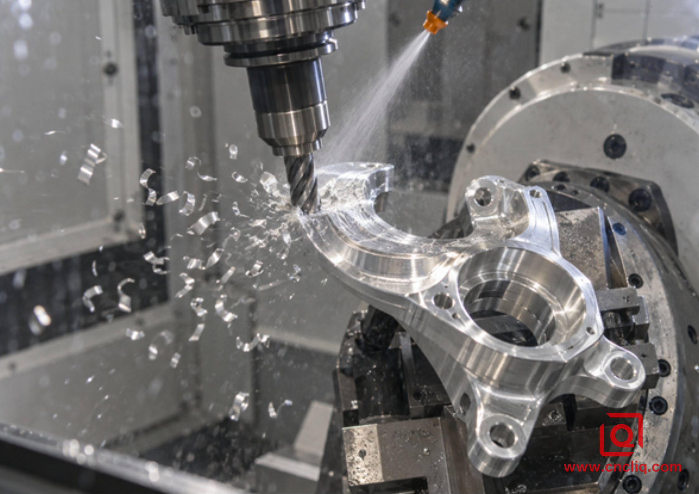
Five-axis side milling of a curved 7075 aluminum component
Change the Recipe for the Operation
The table below is an adjustment map, not a universal speed chart. Start from the exact toolmaker’s data, then account for how the cutter meets the part.
|
Operation |
What changes physically |
Main risk |
Practical adjustment |
|
Open side milling |
One side of the cutter is free and chips can escape |
Chatter from reach or weak workholding |
Keep the assembly short and tune radial engagement before starving the chip load |
|
Adaptive or dynamic roughing |
Engagement is kept relatively constant at a low radial width |
Chip thinning, corner spikes, controller slowdown |
Use the CAM system’s verified chip-thinning model and review every region where engagement rises |
|
Full-width slotting |
Material surrounds both sides of the cutter |
Packed chips, high load, and poor coolant access |
Use open flute space, modest axial depth, strong evacuation, and the cutter maker’s slotting data |
|
Wall finishing |
Small, consistent stock is removed after roughing |
Deflection, rubbing, and witness marks |
Leave uniform allowance, use a sharp dedicated finisher when justified, and avoid stopping on the surface |
|
Floor finishing |
Much of the end geometry can be engaged |
Chip recutting and circular tool marks |
Clear the pocket, check tool-end condition, and use a path that avoids dragging chips across the floor |
|
Thin ribs or plates |
The workpiece moves under cutting and clamping forces |
Taper, vibration, and spring-back |
Reduce radial force, support near the cut, alternate sides where practical, and inspect after unclamping |
At radial engagement below 50% of cutter diameter, maximum chip thickness becomes smaller than the programmed feed per tooth. Sandvik’s published chip-thickness guidance explains why feed can require correction as ae/D decreases. Do not apply a generic multiplier blindly. Let the cutter manufacturer’s calculator or a validated CAM model handle the geometry, and reduce feed locally where corners or leftover stock create a temporary engagement spike.
Complex access can justify multi-axis CNC milling. Tilting the part or tool can replace a long, flexible reach with a shorter assembly. That change often improves the process window more than another RPM adjustment.
Build a Safe First-Cut Validation Ladder
The best settings are not a single point; they are a documented window that remains stable as tools wear, batches change, and the shop temperature moves. A practical prove-out has 4 stages.
1. Audit the physical setup
Confirm the material certificate or purchase specification, drawing revision, cutter part number, usable flute length, holder, gauge length, measured runout, fixture contact, clamp access, and spindle capability. Check that the air blast, mist, or flood coolant reaches the cutting edge throughout the toolpath. Coolant hitting the top of a deep pocket while chips stay at the bottom is not effective evacuation.
2. Review the CAM path, not only the summary panel
Look for full-width entries, tight internal corners, thin leftover wedges, short line segments, small arcs, and regions where the machine may decelerate. Commanded table feed is not always achieved feed. If the control slows but RPM remains fixed, real chip load falls and rubbing can start at the most detailed geometry.
3. Run a supervised proof cut
Watch the first entry and the highest-engagement region. Healthy evidence includes repeatable spindle load, a steady cutting sound, separate chips leaving the cut, and a clean edge without adhered material. Stop for a sharp load change, packed pocket, growing squeal, smeared wall, or visible aluminum on the flute. Do not reach into the machine or inspect until the spindle is safely stopped according to shop procedure.
4. Measure and record
Inspect the features that control function, not just an easy outside dimension. Record accepted RPM, feed, ap, ae, ramp and entry values, tool and holder IDs, stickout, coolant method, spindle load trend, tool-life rule, and inspection result. If the batch changes, the setup sheet gives the next operator a proven baseline instead of folklore.
Read the Chips, Tool, Sound, and Surface Together
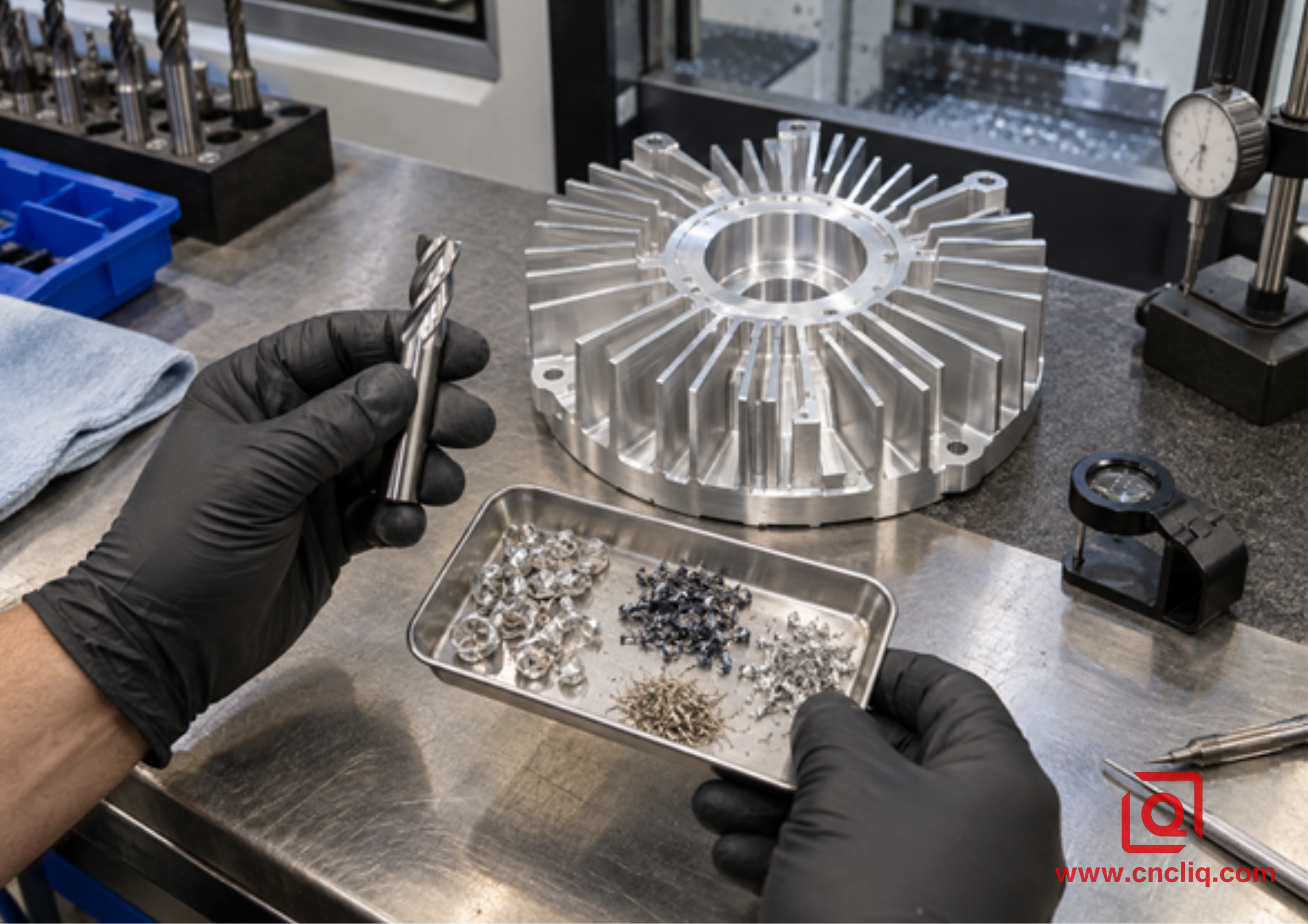
Machinist comparing an aluminum cutter and chip samples
Kennametal’s indexable milling troubleshooting guidance recommends identifying the failure mode and applying corrective actions step by step. That discipline is just as useful with solid-carbide aluminum end mills. If 5 settings move together and the next part improves, the cause is still unknown. That is a poor foundation for the next batch.
|
Symptom |
What it may mean |
Check first |
Controlled next move |
|
Aluminum welded to the edge |
Rubbing, weak lubrication, dull geometry, or chip recutting |
Actual feed, edge condition, chip escape, coolant aim |
Restore a sharp clean edge, correct evacuation, then verify speed and chip load within approved limits |
|
Fine dust instead of formed chips |
Chip thickness is too low or the machine is slowing |
Actual feed in the cut, flute count, and corner motion |
Recalculate feed per tooth and inspect acceleration-limited regions |
|
Loud periodic chatter |
Excess reach, runout, weak support, or unstable engagement |
Holder, stickout, clamping, and corner contact |
Shorten and stiffen first; then alter engagement or speed one variable at a time |
|
Burr grows during the batch |
Edge wear, exit direction, or unsupported material |
Tool-life trend and exit geometry |
Replace or index by a defined criterion and revise the exit if the drawing allows |
|
Size drifts but finish looks acceptable |
Heat, tool deflection, datum shift, or clamping variation |
Part temperature, fixture contact, and measurement trend |
Correct the physical cause before applying wear compensation |
|
Floor scratches after roughing |
Loose chips are being dragged under the tool |
Pocket cleanliness and coolant path |
Add a clean-out strategy before the floor finish pass |
Taken together, those clues usually lead to the fault sooner than noise by itself. Quiet can fool you. An underfed edge may glide along with little drama while it rubs heat into the part.
Feeds and Speeds Must Support Tolerance, Finish, and Cost
For a buyer, cycle time is only one line in the quote. Tool reach, number of setups, fixture complexity, inspection time, deburring, cleaning, surface treatment, and expected tool life can matter more than nominal feed rate. A fast roughing path that distorts a 2 mm wall or leaves inconsistent anodizing stock is not productive.
The drawing should identify critical datums, fits, sealing lands, positional tolerances, and cosmetic zones. Avoid applying the tightest tolerance to every surface. It may force slow finishing and extensive inspection where function does not require them. Liqin’s aluminum CNC milling tolerance and design guide explains how radii, wall thickness, datum strategy, and selective tolerancing affect manufacturability.
Product geometry also changes the parameter plan. A custom CNC-machined aluminum manifold combines open faces, intersecting ports, sealing surfaces, and pockets that require different tools and inspection steps. A smaller 6061 aluminum electrode for 5G surge protection brings different concerns: datum control, fitting features, surface condition, and repeatability after its upstream forming process. Both are “aluminum parts,” but one copied feed-and-speed recipe would be a poor purchasing assumption.
Anonymous Composite Case: 7075 Optical Sensor Cradle
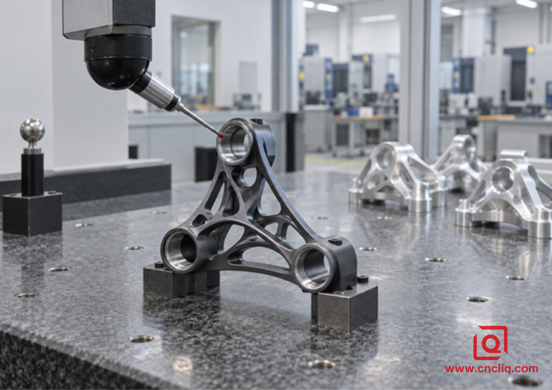
CMM inspection of a complex aluminum optical sensor cradle
The following sanitized composite case is illustrative. It reflects the type of custom aluminum machining Liqin publishes, but it does not disclose one customer’s drawing or promise universal results.
An industrial optics buyer needed a compact 7075-T651 sensor cradle machined from billet. The triangular frame contained 3 angled bearing-style bores, curved weight-reduction windows, and several ribs near 2 mm thick. The functional issue was not maximum RPM. The 3 bores had to retain their positional relationship to a common mounting datum after heavy stock removal, while the slender frame could not show chatter that might complicate final surface treatment.
The process review separated the work into distinct load conditions. A short aluminum-specific roughing tool removed the open stock with constant radial engagement. Rest machining prevented a smaller tool from meeting hidden wedges left by the larger cutter. The part stayed supported during the heaviest removal, then was released and re-established from planned datums before finishing. Multi-axis positioning presented each angled bore to a short, rigid tool instead of using an extended assembly.
The team did not publish one feed rate across every feature. The CAM setup stored separate, approved values for open roughing, rest regions, rib finishing, and bore preparation. Feed optimization reduced the commanded rate where engagement rose, while the operator verified that acceleration did not quietly thin the chip in short movements. Chips were cleared before the wall and floor finishing passes.
Inspection followed the functional chain. Datum surfaces were confirmed first; the 3 bore axes and their positions were then measured on a CMM, followed by rib thickness and visual surface review. Only after that evidence was accepted could the setup become a repeat-production baseline. The lesson is transferable: feeds and speeds belong to the feature, tool assembly, and quality plan—not merely to the alloy name.
Call out thin ribs, angled bores, deep pockets, and datum-critical features in the RFQ; do not leave them for the supplier to infer from a shaded model. Liqin can then compare a 3-axis route with 3+2 or simultaneous 5-axis work and explain where the extra access earns its cost.
What to Send for an Accurate Aluminum CNC Milling Quote
A useful RFQ lets the manufacturing team estimate the actual process instead of pricing from a screenshot. Include:
· A STEP or other usable 3D CAD model plus a revision-controlled 2D drawing.
· Alloy, temper, stock-form requirements, and any material certification needed.
· Critical dimensions, GD&T datums, fits, sealing surfaces, and selective surface-roughness callouts.
· Thread standards, inserts, edge breaks, burr limits, and cleanliness requirements.
· Anodizing, conversion coating, painting, or other finish specifications, including masked areas and cosmetic zones.
· Prototype quantity, production batch size, annual forecast, target delivery, packaging, and destination.
· Inspection deliverables such as first-article reports, CMM data, material records, or coating reports.
· Known assembly problems, prior tool marks, distortion, leakage, or burr concerns.
You can also review Liqin’s broader aluminum product and process capabilities. When the RFQ is ready, request a manufacturing review and competitive quotation. Clear input helps the engineering team respond with a process-aware plan rather than a generic unit price.
FAQ
1. What RPM should I use for CNC milling 6061 aluminum?
RPM depends on cutter diameter and the cutting speed approved for the exact tool. Calculate n = (Vc × 1,000) ÷ (π × D), then confirm the spindle’s real limit and torque range. After selecting the achievable RPM, calculate table feed from flute count and feed per tooth. A generic RPM answer without tool diameter, geometry, engagement, reach, and machine information is incomplete.
2. Is a 2-flute or 3-flute end mill better for aluminum?
With 2 flutes, there is usually more room between edges. That breathing space is useful in a slot, a closed pocket, gummy stock, or a machine with weak flushing. A purpose-built 3-flute tool earns its place elsewhere—open profiles, adaptive roughing, and stable finish cuts where the extra edge can work without choking the flute. The correct choice comes from the exact tool geometry and feature, not flute count alone.
3. Why does aluminum weld to the end mill?
Built-up edge is exactly what its name suggests: aluminum has stuck to the edge and started cutting in place of the carbide. Look first for a chip that is too thin at the chosen RPM, a tired edge, chips going around twice, lubricant missing the cut, a heavy bite, or unnecessary reach. Stop the spindle safely. Clean the pocket, inspect the edge, replace it if damaged, and make the next adjustment inside the toolmaker’s window—one adjustment, not 5.
4. Should aluminum be milled dry, with air, mist, or flood coolant?
The answer depends on the cutter, alloy, machine, operation, and workplace controls. Directed air can clear chips in open cuts; mist adds lubrication; flood coolant can lubricate, cool, and transport chips when it reaches the edge. Deep slots and pockets need special attention because fluid outside the cavity does not prove chip removal inside it. Follow the machine, fluid, ventilation, and tool-supplier guidance.
5. How can a buyer compare aluminum CNC milling quotations?
Compare the proposed material condition, process route, number of setups, critical-feature strategy, inspection scope, finishing, documentation, packaging, lead time, and assumptions—not unit price alone. Ask how the supplier will control thin walls, deep pockets, sealing faces, tool access, and batch drift. A defensible quote should connect the drawing to machining and verification rather than promise a tolerance without explaining the process.
Summary
Reliable CNC milling of aluminum comes from keeping cutting speed, RPM, chip load, flute count, axial depth, radial engagement, rigidity, and chip evacuation connected. Begin with data for the exact cutter, calculate the machine commands, review the real toolpath, and prove the first cut with chips, load, sound, tool condition, and dimensional inspection. Match the recipe to the alloy and feature, document the accepted window, and give your supplier a complete RFQ so speed, tolerance, finish, cost, and delivery can be engineered together.
Contact Information
Company: Ningbo Liqin Industry Co., Ltd.Daily customer maintenance & after-sales support:service@shturl. zhuwanying@cncliq.com
New inquiry, quotation & order discussion:business@shturl. zhouli@chinaliqin.com
Hotline: +86 18757148656
Disclaimer
All technical articles, material specifications, machining recommendations, and surface treatment details published on this blog are for informational and reference purposes only. Please note that general blog insights do not replace signed technical agreements. Because custom parts vary by material heat numbers, machine calibrations, and specific tolerances, binding quality specs are governed solely by your approved CAD drawings, signed contracts, and formal quality plans.
All customer case studies featured on this blog have been thoroughly anonymized and sanitized. The performance metrics, manufacturing workflows, and imagery displayed serve solely to demonstrate our custom machining capabilities and do not represent a single universal standard for all orders.
Liqin Manufacturing Team
Built on 18 years of precision engineering experience, Ningbo Liqin Industry manufactures high-tolerance metal components for demanding global markets. We operate out of a 6,500 m² production hub equipped with over 150 machines, running 4-axis and 5-axis CNC machining, mill-turn machining, cold extrusion, and pressure die casting under one roof. This setup allows us to manage projects seamlessly, taking parts from initial CAD concepts directly to finalized shipments.
We handle quality control with zero compromise. We treat tight tolerances with the engineering discipline they require. Backed by ISO 9001, ISO 13485, and IATF 16949 certifications, our QA engineers run strict IPQC, FQC, and OQC checks on every single production batch. From CMM dimensional mapping and optical profiling to hardness and salt-spray testing, we validate your critical specs upfront—so you receive drop-in ready components with zero assembly headaches or costly line stoppages. On top of manufacturing, you can rely on us for two-hour response times on new RFQs, direct support for prototype sampling, and smooth export shipping across Europe, North America, Asia, and Oceania.
Welcome your inquiries and samples. Visit our website or contact us directly for a competitive quote!
