 English




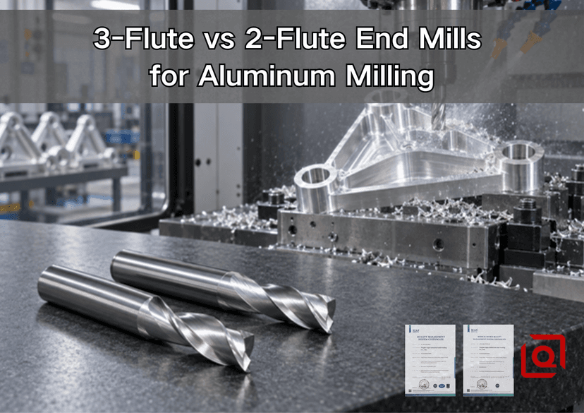
Are you still wondering whether a 3-flute cutter will shorten cycle time—or pack a deep aluminum pocket faster? This shop-floor guide matches the cutter to the feature, machine, chip path, and drawing requirement so the decision protects quality and the quotation.
Quick Answer: Choose the Feature, Not Just the Material
For a deep full-width slot, closed pocket, restricted coolant access, or less-rigid machine, a sharp aluminum-specific 2-flute is usually the safer first trial because each flute has more chip room. For open side milling, constant-engagement roughing, profiling, and semi-finishing on a rigid machine, a well-designed 3-flute can use the extra tooth to raise feed and stability.
Compare complete tool designs, not the number on the box. A polished 3-flute made for aluminum can clear chips better than a blunt general-purpose 2-flute. Flute form, edge, stickout, runout, engagement, alloy, and coolant delivery all belong in the decision.
|
Production question |
Start with 2 flutes |
Start with 3 flutes |
|
Where can the chip go? |
Only upward through a deep slot or obstructed pocket |
Sideways from an open profile or controlled-engagement path |
|
What limits the process? |
Chip volume, spindle power, evacuation, or fragile setup |
Table-feed opportunity, tool deflection, wall stability, or cycle time |
|
Typical first application |
Full-width slotting, small-diameter work, gummy alloy behavior |
Adaptive clearing, side milling, open pockets, semi-finishing, finishing |
|
Main risk to monitor |
Deflection, slower feed, uneven finish from fewer tooth contacts |
Packed flutes, recutting, heat, and rubbing if feed is not recalculated |
|
Buying implication |
A wider process window can be worth more than theoretical speed |
Higher productivity is valuable only when the machine can sustain it |
Our earlier guide compares 2-flute and 3-flute carbide end mills for aluminum. This article focuses on feature-level allocation, shop trials, and OEM quotation decisions.
1. Why One Aluminum Part May Need Both Flute Counts
An end mill never cuts “an aluminum part” in the abstract. It cuts a slot, wall, floor, corner, rib, or interrupted edge, and each feature gives the chip a different exit route. On one component, an open profile may release chips sideways while a cable channel becomes a full-width trap. One cutter for the whole model is convenient, but it can compromise both features.
A reliable plan asks 5 questions per region: how much diameter is engaged; whether engagement spikes in corners; whether air or coolant reaches full depth; whether the tool is roughing, holding a wall, or finishing; and whether a recut chip causes a mark, size drift, or failure.
This method also makes quotations more realistic. A deep slot that needs a dedicated tool and supervised chip clearing should not be costed like an open contour; an open pocket should not inherit a conservative slotting feed when a 3-flute path can run repeatably.
2. The Mechanics Behind the Choice
Flute valley, chip volume, and core strength
Adding a flute divides the tool circumference into more cutting edges and valleys. In a comparable design, 2 flutes normally leave larger valleys for chips. A 3-flute tool often retains more core cross-section and adds another cutting edge, which can support higher tooth-passing frequency and better resistance to bending. “Normally” and “often” are deliberate words: flute geometry is proprietary, so flute count alone cannot tell you the actual valley area or core diameter.
Harvey Performance notes that aluminum forms large chips and flute valleys shrink as count rises; it lists 35°, 40°, and 45° as common specialized helix choices. Haas Tooling describes 2 flutes as a proven clearance choice while engineered 3-flute tools combine polish, rigidity, and evacuation. Use these as principles, not substitutes for the exact tool’s data.
Feed rate changes when flute count changes
Programmed feed is calculated from spindle speed, tooth count, and feed per tooth:
Feed rate = RPM × number of flutes × feed per tooth
Suppose an 8 mm aluminum-specific cutter is approved by its manufacturer for a supervised trial at 16,000 RPM and 0.04 mm/tooth under the planned engagement. A 2-flute tool calculates to 1,280 mm/min. A 3-flute tool calculates to 1,920 mm/min. The 50% difference is mathematical, not a promise of 50% more output.
If you install 3 flutes but keep the old 2-flute feed of 1,280 mm/min, chip thickness falls from 0.04 mm/tooth to about 0.027 mm/tooth. That may turn shearing into rubbing. Real output also depends on acceleration, corner engagement, spindle power, and evacuation. Whenever flute count or RPM changes, recalculate the feed and validate it.
For a broader calculation method, our 6061 aluminum speeds and feeds guide shows how cutting speed, chip load, and engagement work together. Use the exact toolmaker’s application sheet as the controlling source.
3. Match the Cutter to the Actual Milling Feature
|
Feature or condition |
Practical first trial |
What must be verified at the machine |
|
Deep full-width slot |
2-flute aluminum geometry |
Slotting approval, depth limit, chip exit, nozzle aim, spindle load trend |
|
Shallow slot with clear line of sight |
2 or 3 flutes |
Manufacturer’s slot data, bottom-edge condition, chip recutting |
|
Open adaptive pocket |
3 flutes |
Constant engagement through corners, enough feed acceleration, clean escape path |
|
External profile |
3 flutes |
Runout, wall deflection, holder clearance, uniform finish allowance |
|
Long-reach internal wall |
Geometry-specific; do not decide by flute count alone |
Tool overhang, core diameter, chatter, setup access, radial force |
|
Thin-wall finishing |
Often 3 flutes with light, even engagement |
Wall recovery, entry direction, tooth balance, dimensional inspection |
|
Enclosed soft-alloy pocket |
Often 2 flutes plus improved flushing |
Built-up edge, chip nesting, lubrication, safe inspection interval |
|
Small router or modest spindle |
Often 2 flutes |
Minimum stable chip load, acceleration, runout, air delivery, fixture stiffness |
4. When a 2-Flute End Mill Protects the Process
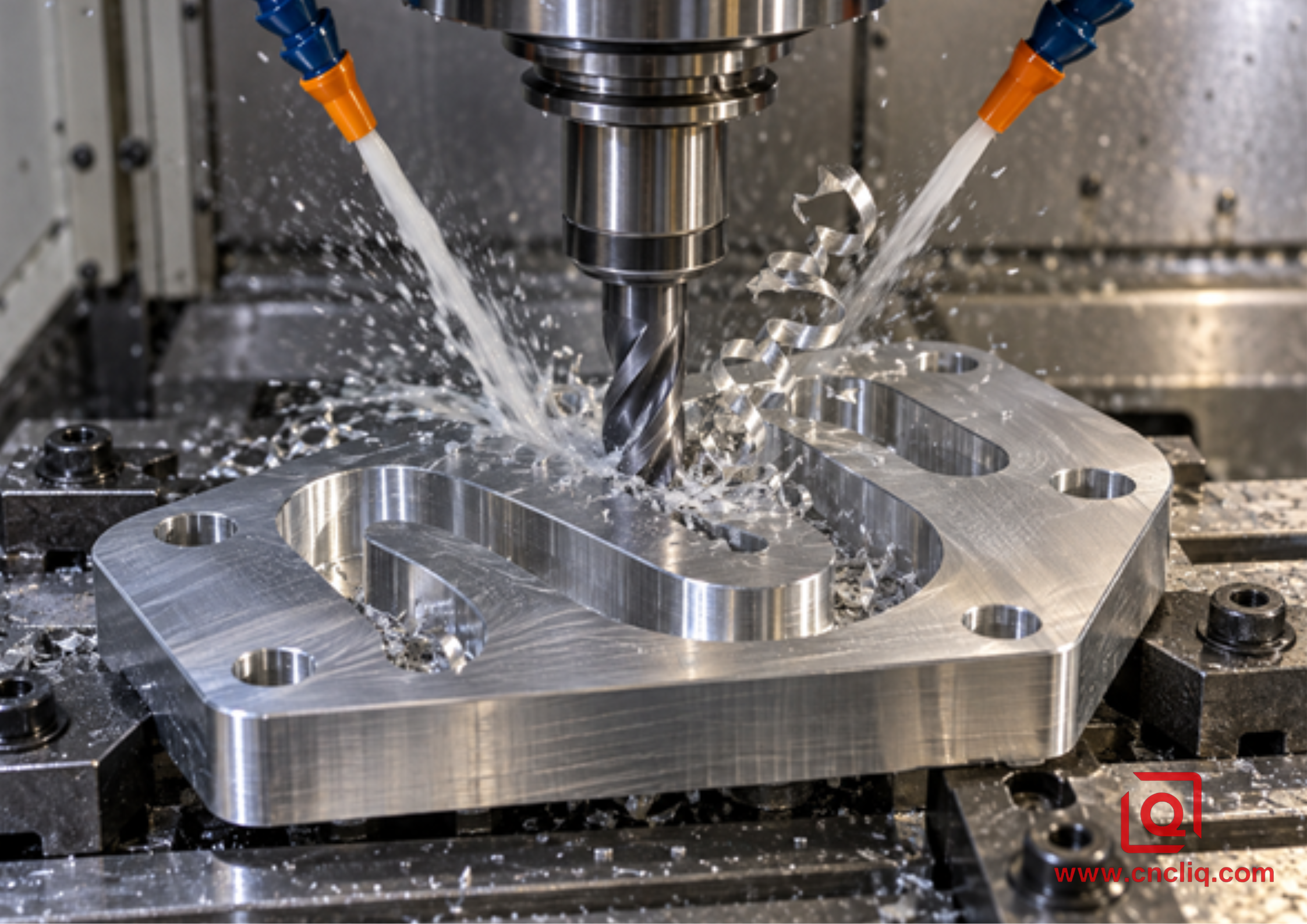
A 2-flute tool earns its place when evacuation is the first constraint. In a 100% radial-width slot, the cutter is wrapped by material and the chip has no open side exit. As depth grows, the chip must travel farther along the flute while coolant or air fights the same narrow path. Larger valleys add useful margin before the flute packs.
That margin matters in enclosed pockets. A nozzle that looks correct above the work may strike the wall at depth while chips circulate below. During prove-out, confirm where the stream lands. A second nozzle, through-tool delivery, a different approach, or a chip-clearing move may matter more than changing brands.
Two flutes can also suit small tools and modest machines, but runout still matters. If one edge protrudes farther, it carries most of the load and the nominal 2-flute cutter behaves like a poorly balanced 1-flute tool.
Choose 2 flutes first for a deep full-width cut, blocked evacuation, bulky or adhering chips, a machine unable to sustain 3 teeth, or an explicit toolmaker recommendation. Flute space adds margin; it does not repair a damaged edge, weak fixture, or blocked nozzle.
5. When a 3-Flute End Mill Converts Rigidity into Output
A 3-flute cutter becomes attractive when chips can leave and the machine is rigid enough to use the extra edge. In constant-engagement toolpaths, low radial engagement exposes the flute while a larger axial depth uses its cutting length. If CAM controls corner engagement, the added tooth can raise table feed without starving each edge.
Open side milling also suits 3 flutes: chips leave the wall, many designs offer a stronger core, and more tooth contacts may improve finish. Low runout is essential; another flute cannot cure an unstable holder or vibrating wall.
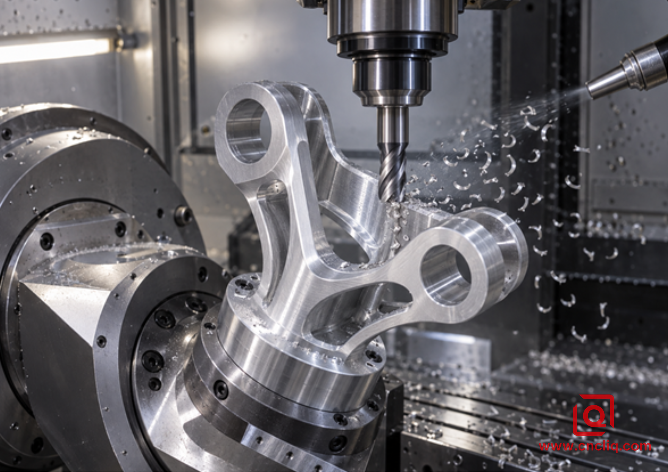
Choose 3 flutes first when radial engagement is controlled, chips have an open exit, table feed limits the cycle, a short rigid tool reaches the feature, and the spindle, controller, and workholding can sustain the calculated load.
Complex access can change the choice. Tilting the work may shorten the tool and open a buried wall. See our guide to multi-axis CNC milling for complex aluminum geometries for the link between access and datum control.
6. Alloy and Temper Still Change the Answer
Do not send an RFQ that says only “aluminum.” Grade, temper, and stock form affect both chip behavior and part stability. 6061-T6 or T651 is a common, predictable baseline, but poor chip load or recutting can still create built-up edge. 7075-T6 or T651 generally produces a crisper chip while demanding a stable edge and setup. Ductile 5052-H32 may smear or adhere more readily, so sharp geometry and reliable lubrication matter. Cast alloys bring different silicon, wear, and porosity considerations; check the cutter maker’s material group before transferring a wrought-alloy plan.
If material choice is open, compare 6061, 7075, and 5052 for CNC milling. Approve any substitution against strength, corrosion, finish, and certification requirements—not machinability alone.
7. Geometry Details That Can Overrule Flute Count
Look beyond 2 versus 3. Aluminum usually favors a sharp, positive-rake edge that shears rather than ploughs, plus a smooth flute that gives soft chips fewer places to adhere. Helix and variable pitch influence chip lift, axial force, edge strength, and vibration; follow the intended operation for that exact series.
Buy only the reach the feature needs. Extra overhang adds leverage that another flute cannot cancel, so revisit the fixture or tool orientation before accepting chatter. Confirm that the corner radius or chamfer is allowed by both CAD and drawing. Bright polished carbide and low-friction coatings are available for non-ferrous work, but suitability depends on substrate, edge preparation, alloy, coolant, and complete tool design—not the coating name alone.
8. Air, Mist, and Coolant: The Delivery Point Matters Most
Air blast suits many open cuts; mist can add lubricity where equipment and workplace rules allow; flood or through-tool coolant can cool and transport chips. None works if it misses the edge. Inspect delivery at actual depth and watch where chips travel. Follow the fluid supplier’s concentration and maintenance requirements, and confirm compatibility with the alloy and downstream finish.
Built-up edge can come from worn geometry, low chip thickness, recutting, engagement, weak lubrication, or heat. Stop safely, correct the cause, and replace a damaged cutter; lowering feed may increase rubbing.
9. A 9-Step Shop-Floor Trial Before Production Release
This 9-step method turns a cutter preference into a documented manufacturing decision.
1. Freeze the input. Confirm drawing revision, CAD model, alloy, temper, stock form, batch quantity, cosmetic zones, and critical characteristics.
2. Map features by chip exit. Mark full slots, open contours, shielded pockets, thin walls, deep floors, and abrupt engagement changes.
3. Select exact candidate tools. Record manufacturer, series, diameter, flute count, flute length, reach, corner style, holder, and recommended material group.
4. Calculate, do not guess. Take cutting speed and feed per tooth from the toolmaker, calculate RPM and feed, and derate for reach, slotting, low rigidity, or limited coolant as instructed.
5. Check the assembly. Measure runout near the cutting edge, minimize stickout, confirm holder condition, and simulate holder and spindle clearance.
6. Aim evacuation at depth. Verify air or coolant reaches the cutting zone throughout the path and gives chips somewhere safe to go.
7. Run one controlled trial. Observe actual feed, spindle load, sound, chip form, burrs, temperature trend, and any evidence of adhesion. Change one variable at a time.
8. Inspect the part and tool. Measure the defined drawing characteristics and surface condition; check the cutter under suitable magnification for built-up edge, chipping, and uneven flute loading.
9. Release a process window. Document the approved tool, offsets, parameters, tool-life rule, inspection frequency, reaction plan, and conditions that require engineering review.
The result is not “3 flutes won.” The result is a controlled route tied to a feature, a tool series, and an inspection plan. That distinction matters when the order repeats 6 months later on a different material heat or machine.
10. Anonymous Composite Case: 7075-T651 Optical-Sensor Carrier
An anonymized composite customer required 7075-T651 optical-sensor carriers with 2 bearing bores, a deep cable slot, open ribs, a thin datum wall, and faces suited to a 3+2 setup. This sanitized example reflects Liqin’s CNC machining services; it does not reproduce a confidential drawing or promise universal results.
Open ribs and profiles stayed on a short 3-flute tool with controlled engagement. The buried full-width slot moved to an aluminum-specific 2-flute, with nozzle aim checked at final depth. A separate tool finished the bearing lands, and fixture orientation exposed the thin wall to a shorter cutter.
In the sanitized trial record, the 3-flute path reduced open-pocket roughing from 8.4 minutes to 6.7 minutes, while the 2-flute slot operation eliminated the recurring chip nest. These figures are illustrative, not guaranteed. The useful outcome was repeatability without forcing one cutter to compromise productivity or clearance.
The control plan checked bearing-bore size and position, wall profile, pocket depth, slot cleanliness, burrs, and datum relationships. Liqin’s quality assurance capabilities describe the broader inspection context. A faster route matters only when the part fits and functions.
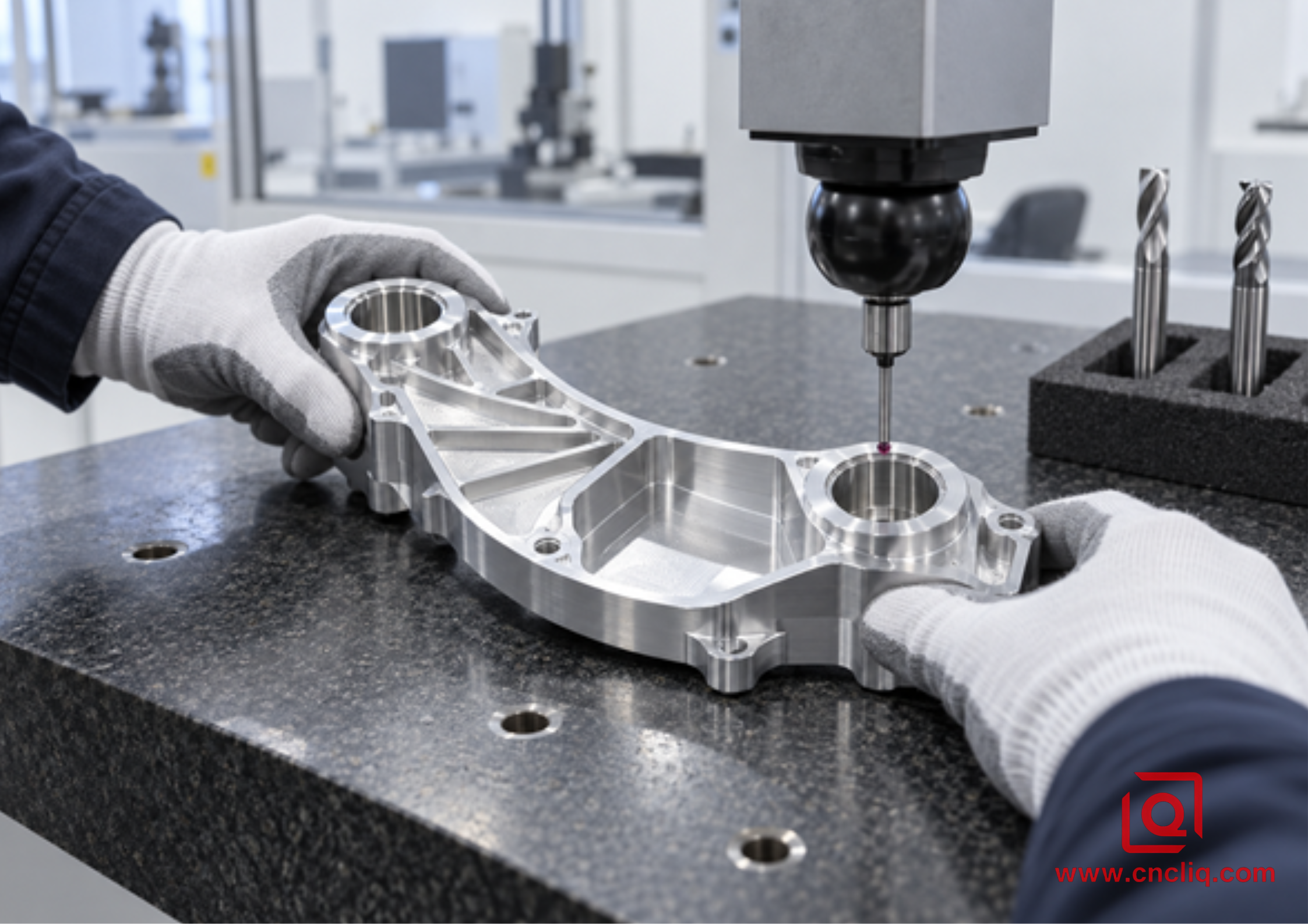
Liqin’s custom CNC-machined aluminum manifold shows another geometry where passages, pockets, sealing faces, and multiple datums demand feature-level planning.
11. Troubleshooting Without Random Parameter Changes
|
Shop-floor symptom |
Likely process mechanism |
First controlled response |
|
Packed flute or compacted nest |
Insufficient flute volume, blocked chip path, or excessive engagement |
Stop safely; clear and inspect; improve evacuation; reduce engagement; trial 2 flutes if approved |
|
Bright aluminum cap on the edge |
Adhesion caused by rubbing, heat, worn edge, poor lubrication, or recutting |
Replace damaged tool after correcting chip load, delivery, and edge suitability |
|
Repeating wall bands |
Runout, tooth-load imbalance, chatter, deflection, or uneven stock |
Measure runout; shorten reach; check holder and allowance; then compare a rigid 3-flute finish tool |
|
Random floor scratches |
Loose chips dragged under the bottom edge |
Redirect chips, revise path direction, inspect bottom edge, and clean before finishing |
|
Load spike at corners |
Toolpath engagement exceeds the straight-cut condition |
Smooth the corner, reduce local engagement, or use verified feed optimization |
|
Finish worsens after changing to 3 flutes |
Old table feed reduced chip thickness per tooth |
Recalculate feed from the approved chip load; verify actual machine feed and acceleration |
|
Tool breaks only near final depth |
Chip packing, poor depth delivery, long reach, or accumulated edge damage |
Review the last path segment, nozzle aim, flute condition, and permitted depth of cut |
Change one variable at a time. Altering RPM, feed, engagement, depth, and coolant together may improve the next part without revealing which change fixed the mechanism.
12. Turn Cutter Choice into a Better CNC Milling RFQ
A supplier cannot plan cutter use from a rendering alone. Send native 3D CAD and a controlled 2D drawing with alloy, temper, stock preference, quantities, annual demand, critical dimensions, GD&T datums, threads, functional roughness, edge breaks, finish, cosmetic zones, inspection documents, packaging, and destination. Highlight deep slots, thin walls, radii, inaccessible pockets, sealing faces, and prior burr, chatter, chip-welding, or tool-life problems. These details let engineering price tooling, fixtures, prove-out, inspection, and risk with fewer assumptions.
If your drawing contains a mix of open profiles and chip-trapping channels, ask the supplier how it plans to divide roughing, slotting, and finishing tools. The answer should connect tool geometry to engagement, evacuation, and inspection—not merely say “we use 3 flutes for aluminum.”
Need a process-aware review for a custom aluminum housing, bracket, manifold, robotics component, or precision carrier? Send Liqin your STEP file, controlled drawing, material condition, quantity, finish, and critical features through the contact page. Our engineering team can review feature access, tool reach, datum strategy, inspection needs, and whether a mixed 2-flute/3-flute route supports a stable quotation.
FAQ
1. Is a 3-flute end mill always faster than a 2-flute end mill in aluminum?
No. At equal RPM and approved feed per tooth, 3 flutes calculate to a higher table feed, but real cycle time also depends on chip evacuation, engagement, machine acceleration, spindle power, toolpath length, and interruptions. A 3-flute tool that packs a deep slot is not productive. It is most valuable when an open or controlled-engagement cut lets the machine use the extra edge without recutting chips.
2. Should I use 2 flutes or 3 flutes for a full-width aluminum slot?
A 2-flute aluminum-specific end mill is usually the safer starting candidate because its larger flute valleys provide more chip-carrying space, especially as the slot becomes deeper or coolant access worsens. A 3-flute tool may work in a shallow slot if its manufacturer rates it for that duty and evacuation is strong. Confirm the exact tool’s slotting limits and prove the cut under supervision.
3. Why did the 3-flute tool leave a worse finish even though it has more cutting edges?
More edges improve finish potential, not certainty. Keeping a 2-flute table feed after changing to 3 flutes reduces feed per tooth and may cause rubbing. Runout may also force one flute to carry most of the cut. Check the feed calculation, holder condition, runout near the edge, tool projection, wall deflection, chip recutting, and uniformity of the finishing allowance before blaming flute count.
4. Which cutter is better for 6061, 7075, or 5052 aluminum?
All 3 alloys can be machined with suitable 2-flute or 3-flute tools, so the feature and exact cutter design remain decisive. 6061 is a practical baseline but can still form built-up edge; 7075 generally produces a crisper chip while demanding a stable setup; ductile 5052 may smear or adhere more readily. Use a sharp aluminum-specific geometry, follow the toolmaker’s material data, and validate chip control on the actual temper and stock form.
5. What should I send Liqin for a reliable aluminum CNC milling quote?
Provide a STEP model and revision-controlled 2D drawing, alloy and temper, quantity and forecast, critical tolerances and datums, threads, functional roughness, surface treatment, cosmetic zones, inspection or certification requirements, packaging, and delivery target. Highlight deep slots, thin walls, small internal radii, difficult tool access, sealing faces, and prior machining failures so tooling, fixtures, prove-out, and quality control can be priced with fewer assumptions.
Summary
Choose a 2-flute aluminum end mill when chip space and evacuation dominate, and choose a 3-flute tool when open engagement, rigidity, and machine capability can convert another cutting edge into higher feed or better stability. Treat flute count as one part of the tool system, recalculate feed whenever tooth count changes, assign cutters by feature, and release production only after a documented 9-step trial verifies chips, load, tool condition, dimensions, and surface quality.
Contact Information
Company: Ningbo Liqin Industry Co., Ltd.
Daily customer maintenance & after-sales support:service@shturl. zhuwanying@cncliq.com
New inquiry, quotation & order discussion:business@shturl. zhouli@chinaliqin.com
Hotline: +86 18757148656
Disclaimer
All technical articles, material specifications, machining recommendations, and surface treatment details published on this blog are for informational and reference purposes only. Please note that general blog insights do not replace signed technical agreements. Because custom parts vary by material heat numbers, machine calibrations, and specific tolerances, binding quality specs are governed solely by your approved CAD drawings, signed contracts, and formal quality plans.
All customer case studies featured on this blog have been thoroughly anonymized and sanitized. The performance metrics, manufacturing workflows, and imagery displayed serve solely to demonstrate our custom machining capabilities and do not represent a single universal standard for all orders.
Liqin Manufacturing Team
Built on 18 years of precision engineering experience, Ningbo Liqin Industry manufactures high-tolerance metal components for demanding global markets. We operate out of a 6,500 m² production hub equipped with over 150 machines, running 4-axis and 5-axis CNC machining, mill-turn machining, cold extrusion, and pressure die casting under one roof. This setup allows us to manage projects seamlessly, taking parts from initial CAD concepts directly to finalized shipments.
We handle quality control with zero compromise. We treat tight tolerances with the engineering discipline they require. Backed by ISO 9001, ISO 13485, and IATF 16949 certifications, our QA engineers run strict IPQC, FQC, and OQC checks on every single production batch. From CMM dimensional mapping and optical profiling to hardness and salt-spray testing, we validate your critical specs upfront—so you receive drop-in ready components with zero assembly headaches or costly line stoppages. On top of manufacturing, you can rely on us for two-hour response times on new RFQs, direct support for prototype sampling, and smooth export shipping across Europe, North America, Asia, and Oceania.
Welcome your inquiries and samples. Visit our website or contact us directly for a competitive quote!
