 English





Here is the shop-floor scene. The aluminum body looks fine off the lathe. After milling, though, its drilled holes miss the bore. The first instinct is to blame one operation. Perhaps neither deserves it. The lathe held size. The mill followed its new fixture. What disappeared between them? The common reference.
Where does turn-mill machining earn attention? Right in that gap. Does the machine name settle the issue? No. Does one extra axis guarantee a good part? No. A smaller question is more useful. Look at the working datum system. Bore, face, pilot, ports, flats, and rear details either stay tied to it or they do not.
Where should the jaws touch? Which cuts happen while the body is stiff? When do you finish the bore? How does a chip escape a cross-hole? What origin does the CMM use? Small questions, yes. But answer them badly and one-hit machining becomes a line on a quotation, nothing more.
Quick Answer: Does This Part Belong on a Turn-Mill?
Is the basic body rotational? Does it also carry flats, radial holes, offset slots, side ports, a keyway, or work on the cut-off end? Do those details locate from a turned bore, shoulder, diameter, or face? Three yes answers? Put turn-mill on the review list.
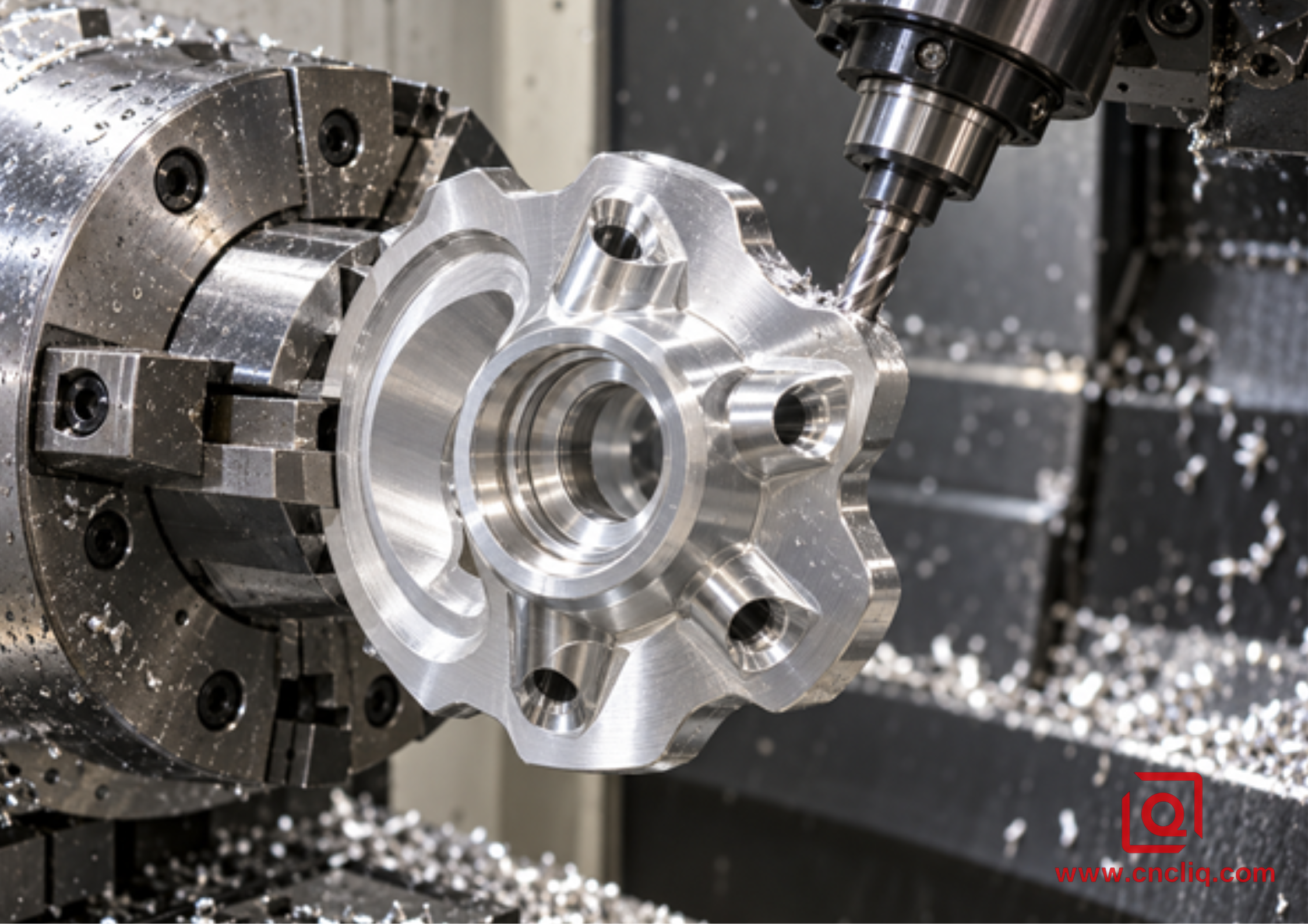
What happens inside the machine? The main spindle turns the round work. Live tools drill and mill. C-axis motion sets the angle. Y travel reaches off center. Need an angled approach? Bring in a B-axis, if the job earns it. Need the rear face? Let the sub-spindle expose that end.
What disappears from the route? The walk to another machine. The wiped fixture. The new origin. The hope that grip two repeats grip one. What stays? Runout, jaw force, heat, chips, transfer error, and measurement. Fewer variables, then. Never zero.
Would a plain shaft with four clearance holes justify all of that? Probably not. A drill fixture may be quicker. What about a thin housing with a bearing seat, three clocked ports, an O-ring face, and back threads? Now the handoff carries real risk. What makes the case? Geometry. Not an axis count.
One Hit, but How Many Clamping States?
Does done-in-one mean the part never changes hands inside the machine? Not always. Sometimes the main chuck hands the work to the opposite chuck. Automatic or not, the second chuck creates another clamping state. Count it.
What belongs in the handoff plan? Pickup diameter. Grip length. Seating face. Pressure. Part-off allowance. Runout check. Miss one? The transfer has quietly become a second setup.
Bore, pilot, and sealing face share an axis? Finish that group on the same spindle. What can move to backworking? A rear thread or noncritical face often can. What if the rear pattern locates tightly from the bore? Carry that relationship through the transfer and the CMM program.
Can a probe rescue weak workholding? No. It reports a location. It cannot stop a thin wall from moving. Can simulation detect a chip behind a jaw? No. It can show clearance. It cannot feel poor seating.
Why start with the drawing? It tells you what must remain related. ISO 1101:2017 is the reference behind the drawing vocabulary. Form and orientation sit there, as do location and run-out. Will the standard choose your chuck? Of course not. What will it expose? The intended relationships.
Which Geometries Earn an Integrated Route?
Try this on the drawing. Start with a pencil at the bore. Continue through the turned diameters, shoulders and tapers; add grooves and coaxial threads. A different pencil gets the cross-holes and flats; ports, keyways, bolt circles, side pockets, and offset slots join that group. Where do their dimensions point? Do they point back to the first group again and again? Then protect that relationship.
Take a motor end cap. What governs rotation? Bearing bore and locating spigot. What stops it axially? The mounting face. And what creates the second operation family? Usually the drilled pattern. Want a physical example? Liqin's precision motor flange and front end cap carries that mix.
Now pick up a fluid body. Is port diameter the whole job? No. Clocking matters. So do intersection burrs, sealing lands, thread direction, and distance from the bore axis. Judge one by itself and the functional picture is incomplete. A related product family is Liqin's custom aluminum hydraulic manifold.
What other candidates appear often? Sensor barrels. Optical bodies. Robotic couplings. Shaft adapters. Lightweight rotors. Threaded fittings. Does the product name decide? No. A large sensor body can be simple. A small fitting with one critical cross-port? Sometimes it is the harder job.
Can the Team Say the Datum Chain in One Breath?
What locates the component in assembly? Which axis controls rotation? Which face stops it axially? Where do the ports and flats locate? Can inspection rebuild the same logic?
If those answers wander, should the shop choose a more elaborate machine? Not yet. Repair the datum story first. A capable machine cannot repair a vague drawing.
What goes wrong during manual re-clamping? Nothing dramatic, usually. One chip sits under a jaw. A burr blocks the seat. Soft jaws have worn a little. Pressure changed. Someone indicates the easy diameter, not the functional bore. Ordinary shop events. That is why they matter.
What does an integrated cycle improve? It removes a few chances to rebuild location badly. What stays on the control list? Jaw preparation, runout, tool condition, seating, and released-part inspection.
For a closer process comparison, open Liqin's article on CNC turning versus turn-mill machining for concentric aluminum housings. What does that comparison follow? The bore, pilot, face, and port chain in round housings.
Is Live Tooling Enough?
What can a driven turret do well? On-center drilling. Radial holes. Flats. Modest slots. Tapping. When does Y travel help? When work sits away from the spindle centerline.
Can polar interpolation replace every Y move? No. Can a B-axis improve every job? No. Do angle, reach, or a compound form demand a B-axis? If not, leave it out of the sales pitch. A sub-spindle solves a different problem by opening the cut-off end inside the cycle.
Test the supplier's plan with two opening questions: which spindle finishes the bore, and where is the pickup diameter? How much support remains before slotting? Which holder comes near a jaw? Is the live tool's torque useful at the programmed speed? What, exactly, verifies the transfer?
Is a machine list enough? No. Is a simulation screenshot enough? No. What should a useful quotation explain? The route against the drawing. Assumptions can remain in an early quote. Hidden assumptions cannot.
Aluminum Is Easy to Cut. The Process Is Not Always Easy.
Does aluminum remove quickly? Yes. Does it always leave cleanly? No.
What happens when a supposedly sharp edge starts rubbing? Aluminum can stick to it. The edge is no longer the edge you set. Finish goes cloudy. Burrs grow. Diameter wanders. Tempted to add an offset? Stop and inspect the insert first. An offset made against built-up material turns wrong the moment a fresh edge goes in.
Where else does trouble start? Follow the chip. A ribbon wraps a shoulder. One curl stays in a pocket and returns when the C-axis indexes. Another catches at a cross-hole and scratches the bore. More speed fixes that? No.
What helps? Start with sharp aluminum geometry. Keep enough chip thickness. Shorten the overhang. Control engagement. If the process permits fluid or air, point it at the cutting edge. More important: draw the chip an exit path.
For the turning side, Liqin's aluminum chip-control guide deals with insert shape, feed, coolant direction, and signs of built-up edge. Pocket milling has a different escape problem; the deep-pocket chip evacuation guide traces that route to the opening.
Can one blog number be safe in every shop? No. Toolmaker data is the first trial point, not the last word. Where do you finish? At the machine, after holder, alloy heat, overhang, coolant, engagement, and surface result have had their say.
Can Temperature Move a Passing Dimension?
The first-off is warm in your hand. Ignore it? Better not.
A number helps here. Open the NIST-hosted ASM reference Properties of Wrought Aluminum and Aluminum Alloys and common wrought aluminum is shown near 23 micrometers per meter-kelvin. Now take a 100 mm feature through a 10 degrees Celsius change: about 0.023 mm.
Use that as a blanket correction? No. Treat that figure as scale, not a universal correction. The shop lesson? A warm reading and a stable reading may disagree. Chase nominal while the part is warm? The settled part may move away from target.
Does an RFQ that says only aluminum tell the shop enough? No. Specify alloy and temper. Then name the stock route: bar, plate, extrusion, forging, or casting. Certification and substitution rules belong beside them. A drawing may show 6061-T6 changing to 7075-T651 in a single line. On the shop floor, that one line deserves a fresh review.
The source for recognized alloy designations is the Aluminum Association. For day-to-day 6061 machining context, Liqin's 6061 aluminum tooling guide makes a useful companion.
A Quote Needs a Sequence, Not a Machine Name
Does one fixed route fit every part? No. Can a buyer recognize sound logic? Yes. Follow the questions.
1. Lay model and drawing together. A thread or datum conflict needs an answer before programming. So does a disagreement in tolerance, finish, edge condition, or inspection note.
2. Add the actual stock to a jaw sketch. Label bar size and jaw length, then mark saw allowance, pickup surface, and support.
3. While the body still has its stiffness, face it, rough it, open the bore, and keep stock removal balanced.
4. Which surfaces share an axis? Finish bore, pilot, shoulder, seal face, and groove in their common grip.
5. How are indexed features reached? Use short assemblies. Check holder, nut, jaw, spindle nose, and nearby stations.
6. Where does each burr form? Name a method before production. Use in-machine or validated secondary deburring as needed.
7. What changes at transfer? Define pickup, force, contact length, seating, part-off condition, and runout.
8. What remains on the back? Finish only the features assigned to that clamping state.
9. What proves the route? Use functional datums for the first article and risk-based in-process checks.
Collision simulation is preparation work, not a cutter animation. Rebuild the actual envelope around the cut: jaws and holder, spindle nose and turret, probe and stock, remaining material and the opposing spindle. What about approach and retract? Those moves belong there too.
Where does final proof occur? On the floor. Is the stock seated? Check it. Runout? Check it. Stickout and coolant reach? Check both. Watch the load, follow the chips, and measure after release.
Does a Thin Wall Belong to the Chuck?
Can a bore read round in the chuck and turn lobed after release? Yes. Why? While cutting, part, jaws, and stock act like one elastic system. Open the chuck and that system is gone.
Which inputs matter? Jaw area. Pressure. Grip length. Wall transition. Removal order. Tool pressure. Heat. Residual stress. Will a light finish pass cure every case? No.
What should soft jaws do? Spread load and protect the surface. What must the grip resist? Turning torque plus live-tool side load. Push the sub-spindle too hard and a bore may squeeze. Too lightly? The part can move.
How is the setting proved? Measure the released component. Shop habit is not evidence.
What about texture? A bright face may not be flat. A good Ra value may not be square to the bore. Which surfaces matter? State them. Which measurement method and direction? Define them. Before or after anodizing? Say so. Keep cosmetic acceptance in its own box. Sealing and locating function belong in another.
Inspection Must Follow the Function
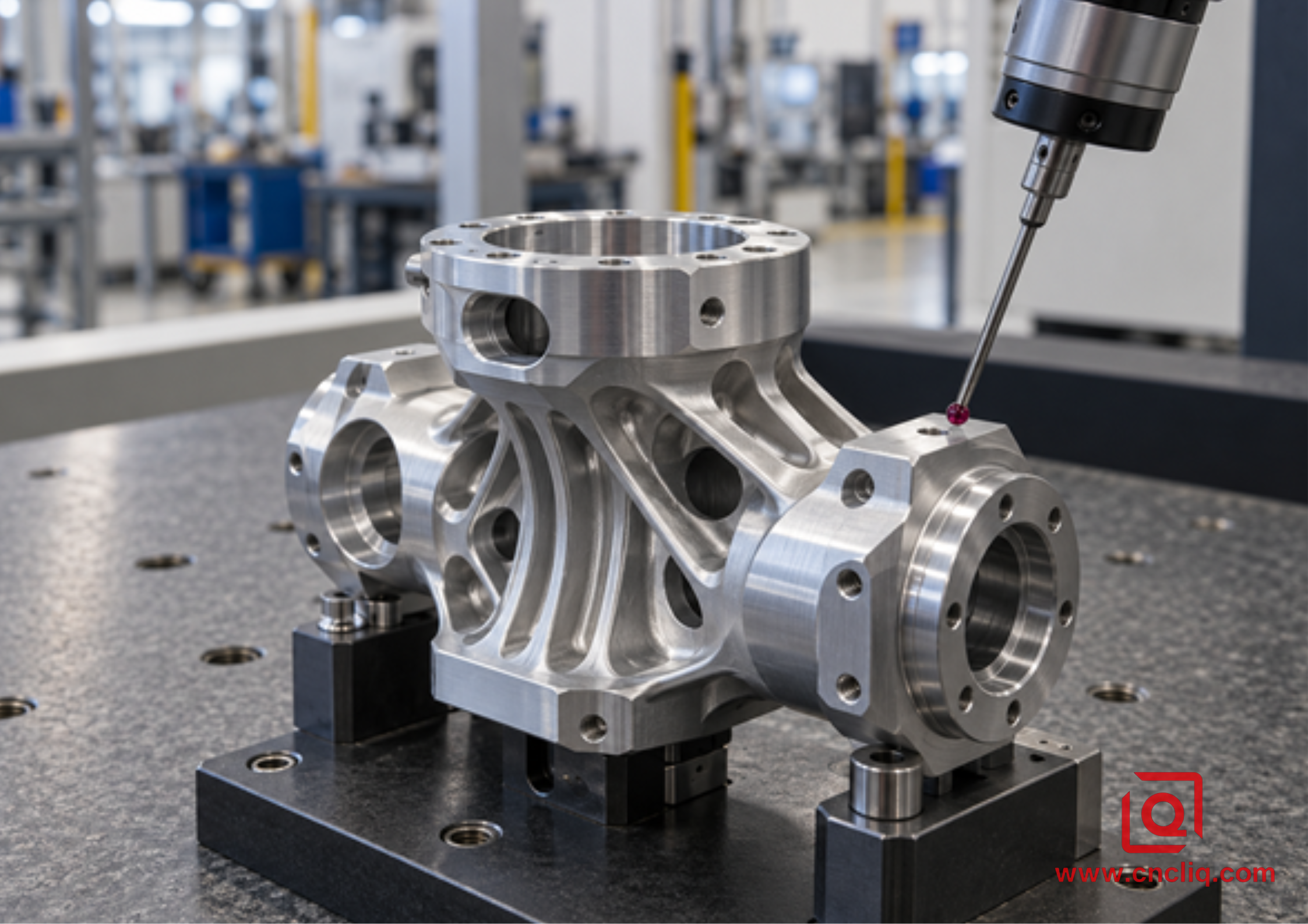
How do you tell whether the integrated route worked? Inspect from the same functional references that drove the cuts. Anything else tells only half the story.
|
Characteristic |
Useful verification |
Weak shortcut |
|
Bore-to-pilot runout |
Rotate from the functional axis or use a validated CMM method |
Measure both diameters separately |
|
Radial-port location |
CMM true position from the bore axis and axial face |
Check hole diameter only |
|
Face orientation |
Evaluate the face relative to the functional axis |
Check thickness at one point |
|
Flat-to-slot clocking |
CMM or a dedicated gauge from one angular reference |
Measure both from an arbitrary edge |
|
Thread function |
Correct go/no-go gauge plus location where critical |
Visual inspection |
|
Surface texture |
Calibrated instrument and defined direction |
Judge reflection by eye |
Agree on first-article evidence before production. Full CMM report? Material certificate? Coating report? Capability study? Special traceability? Name it in the RFQ. Finding a missing document after the cartons are packed helps nobody.
Anonymous Customer Case: Robotic Fluid Rotary Adapter
The following case is anonymized and sanitized from Liqin's machining scope. Its purpose is narrow: explain the route. Results still belong to the approved drawing for each order.
A factory-automation buyer sent a compact 6082-T6 rotary adapter. The screen view looked modest. Then we counted the work: a finished center bore, twin sealing diameters, O-ring face, three ports at 120 degrees, offset cable slot, wrench flat, and threads on the rear.
The original route went from lathe to transfer fixture to vertical mill. Bore size stayed stable. Port position after relocation did not. Worse, hand deburring at the cross-holes worked too near the sealing edge for comfort.
What did the new route protect first? The common coordinate system. Bore, pilots, O-ring face, ports, slot, and flat stayed on the main spindle. Bulk stock came off while the body still had support. Then came the bore and sealing group. C-axis for the ports. Y travel for the offset slot. At the intersections, a controlled back-chamfer handled the burr.
What stayed for the cut-off side? The sub-spindle held a prepared pickup diameter and exposed the back face plus mounting threads. For inspection, the bore axis and O-ring face became the references. CMM checks covered port position, angular spacing, flat location, and the back pattern. Plug and thread gauges? They covered the functional sizes.
What changed most? Three manual machine setups became one integrated cycle with an internal spindle transfer. Was the headline cycle time the big win? No. The shaky port relationship moved into one planned coordinate system. Acceptance still came from the approved drawing, first-article evidence, batch controls, and tool control.
When Are Two Machines the Better Answer?
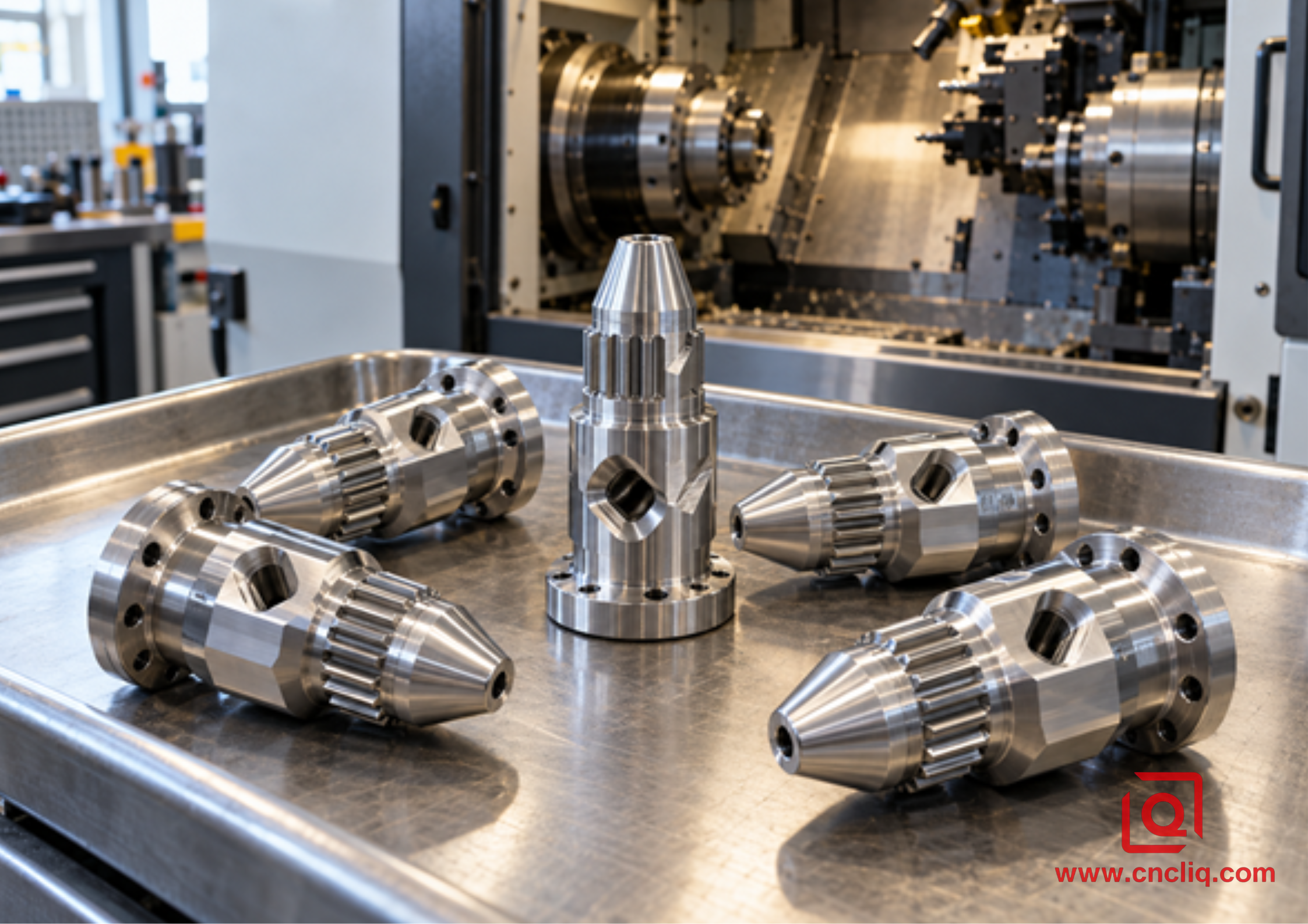
Turn-mill is a process choice, not a prize. A simple turned body with loose hole location may run faster through a lathe and a drill fixture. A broad, mostly prismatic part may be happier on a machining center. At high volume, pause again. Could a lathe and mill run side by side and keep the line moving better? If yes, the elegant all-in-one cycle may lose.
Where is the boundary? Follow each dimension that crosses from a turned surface to a milled one. None critical? A proven second fixture may be perfectly sensible. If a port, flat, or slot must follow the finished bore closely, the transfer deserves much more suspicion.
Liqin's comparison of 3-axis and 5-axis aluminum milling helps with the machining-center side of that decision. Forget the machine contest. Which route protects the required relationships with less total risk?
One setup can be a slippery phrase. Is there a hand flip, bench deburring, grinding, or an unmentioned machine visit? Write down every clamping state. Beside each state, write the critical features finished there. The route becomes much easier to judge.
What Are You Paying For?
A turn-mill hour can cost more than a basic lathe hour. But the purchase order pays for accepted parts, not isolated machine hours. Count setup and queue time. Add the fixture, handling, inspection, and deburring. Then ask the uncomfortable question: what does a scrap cost after nearly every feature is finished?
A practical cost review uses three clocks. One clock runs while metal is being cut. Another runs while people set, move, clean, inspect, and deburr the part. The third is the calendar: how long the order waits between operations. A lower machine rate can lose the comparison on the second or third clock.
Cost pressure usually comes from a few familiar places:
· Simultaneous-axis programming and a serious collision review.
· A short or awkward pickup surface at the sub-spindle.
· Long driven-tool reach, special holders, or a back-chamfer tool.
· A tight relationship between a turned datum and a milled feature.
· Burr, texture, coating, cleanliness, or reporting rules that need extra handling.
· Certified material, small batches, or frequent drawing revisions.
Loosen every tolerance? No. Mark the dimensions that keep the part fitting, sealing, moving, or assembling. Begin the cost review with everything left unmarked. Liqin's guide to CNC machining tolerances and cost shows why an unnecessary tight callout adds both machining work and inspection work.
Nine Questions to Put Beside the RFQ
1. Do the native 3D model and controlled drawing show the same revision? If not, stop there.
2. Name the alloy, temper, and stock form. Add the certificate requirement and any permitted substitution.
3. Point out the axis and face that locate the part in assembly. Mark sealing lands, bearing fits, and clocked details.
4. Does each tight dimension apply before finishing, after it, or twice?
5. Prototype count? Normal batch? Repeat interval? Add annual volume when known.
6. What counts as an acceptable edge? Add the burr limit, cleaning need, cosmetic expectation, and packaging method.
7. Which clamping states does the supplier plan? Have the quotation name the machine layout, pickup surface, and transfer logic.
8. Which records ship with the batch? Name only the ones the job uses: FAI, CMM, material, coating, capability, or traceability.
9. What mates to this component? How can that interface fail? That single note often improves DFM feedback more than another general tolerance.
Have a candidate part now? Send the STEP file and controlled drawing to Liqin. Add material, quantity, finish, and the dimensions that drive assembly. The pre-quote review can then follow the grip, datum chain, tool access, transfer, chip path, burr, and inspection plan. Request it through the Liqin contact page.
FAQ
1. Does live tooling always mean full turn-mill capability?
Not by itself. Imagine two lathes, both advertised with live tooling. One can spin a drill in the turret. The other also moves in Y, changes tool angle, and transfers work to a second spindle. Those are different process envelopes. Check the actual moves needed by the drawing before accepting the machine label.
2. Does one-hit machining guarantee the drawing?
No. One hit describes the route, not the accuracy by itself. It avoids certain manual re-clamping errors, which helps a port stay related to its bore. Still on the bench are chuck distortion, heat, runout, wear, transfer, and measurement. Proof comes after release and stabilization, using the agreed datums on the first article.
3. Should every turn-mill aluminum part use 6061?
No. Start with load, environment, weight, finish, and the required material properties. That may lead to 6061 or 6082 for one component and 7075 for another. Temper and stock form can matter as much as the familiar alloy number. Put the approved designation on the RFQ; route any substitute back to the design authority.
4. Is turn-mill too expensive for a prototype?
Sometimes it is the cheaper prototype route. Picture three fixtures, two fresh indications, and an inspection handoff on conventional equipment. Extra programming may be worth paying for if it removes those moves. Now picture a plain collar; the answer flips. Compare the complete route and delivery risk, not one hourly rate.
5. What information helps Liqin return a reliable quote faster?
Give the estimator one clean revision of the model and drawing. Beside it, note alloy, temper, prototype and batch quantities, datums, tight features, threads, texture, finish, edges, cleaning, records, and delivery. Circle every turned-to-milled relationship. A short note about the mating part and its failure mode is especially useful.
Summary
Turn-mill earns its place when one datum story must connect the turned body to ports, flats, slots, or rear work. The machine badge proves nothing by itself. Look for a credible grip, sequence, chip, burr, transfer, and inspection plan, then compare accepted-part evidence and total risk.
Contact Information
Company: Ningbo Liqin Industry Co., Ltd.
Daily customer maintenance & after-sales support: service@shturl. zhuwanying@cncliq.com
New inquiry, quotation & order discussion: business@shturl. zhouli@chinaliqin.com
Hotline: +86 18757148656
Disclaimer
All technical articles, material specifications, machining recommendations, and surface treatment details published on this blog are for informational and reference purposes only. Please note that general blog insights do not replace signed technical agreements. Because custom parts vary by material heat numbers, machine calibrations, and specific tolerances, binding quality specs are governed solely by your approved CAD drawings, signed contracts, and formal quality plans.
All customer case studies featured on this blog have been thoroughly anonymized and sanitized. The performance metrics, manufacturing workflows, and imagery displayed serve solely to demonstrate our custom machining capabilities and do not represent a single universal standard for all orders.
Liqin Manufacturing Team
Built on 18 years of precision engineering experience, Ningbo Liqin Industry manufactures high-tolerance metal components for demanding global markets. We operate out of a 6,500 m² production hub equipped with over 150 machines, running 4-axis and 5-axis CNC machining, mill-turn machining, cold extrusion, and pressure die casting under one roof. This setup allows us to manage projects seamlessly, taking parts from initial CAD concepts directly to finalized shipments.
We handle quality control with zero compromise. We treat tight tolerances with the engineering discipline they require. Backed by ISO 9001, ISO 13485, and IATF 16949 certifications, our QA engineers run strict IPQC, FQC, and OQC checks on every single production batch. From CMM dimensional mapping and optical profiling to hardness and salt-spray testing, we validate your critical specs upfront - so you receive drop-in ready components with zero assembly headaches or costly line stoppages. On top of manufacturing, you can rely on us for two-hour response times on new RFQs, direct support for prototype sampling, and smooth export shipping across Europe, North America, Asia, and Oceania.
Welcome your inquiries and samples. Visit our website or contact us directly for a competitive quote!
