 English




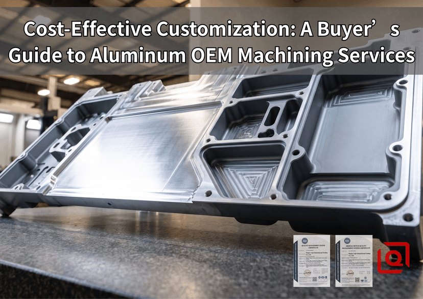
Throw away the generic CAD cheat sheets. If your procurement spec simply slaps a blanket ±0.005 mm tolerance across a 6061-T6 plate and calls it a day, you’re not buying precision—you’re burning cash on machine hours, scrapped stock, and avoidable tool wear. In OEM aluminum manufacturing, true cost-efficiency isn't achieved by pushing vendor margins into the red; it's engineered directly into the G-code, the fixture design, and the raw billet selection before a single cutter touches the spindle.
The Hidden Margins in Billet Metallurgy and Thermal Drift
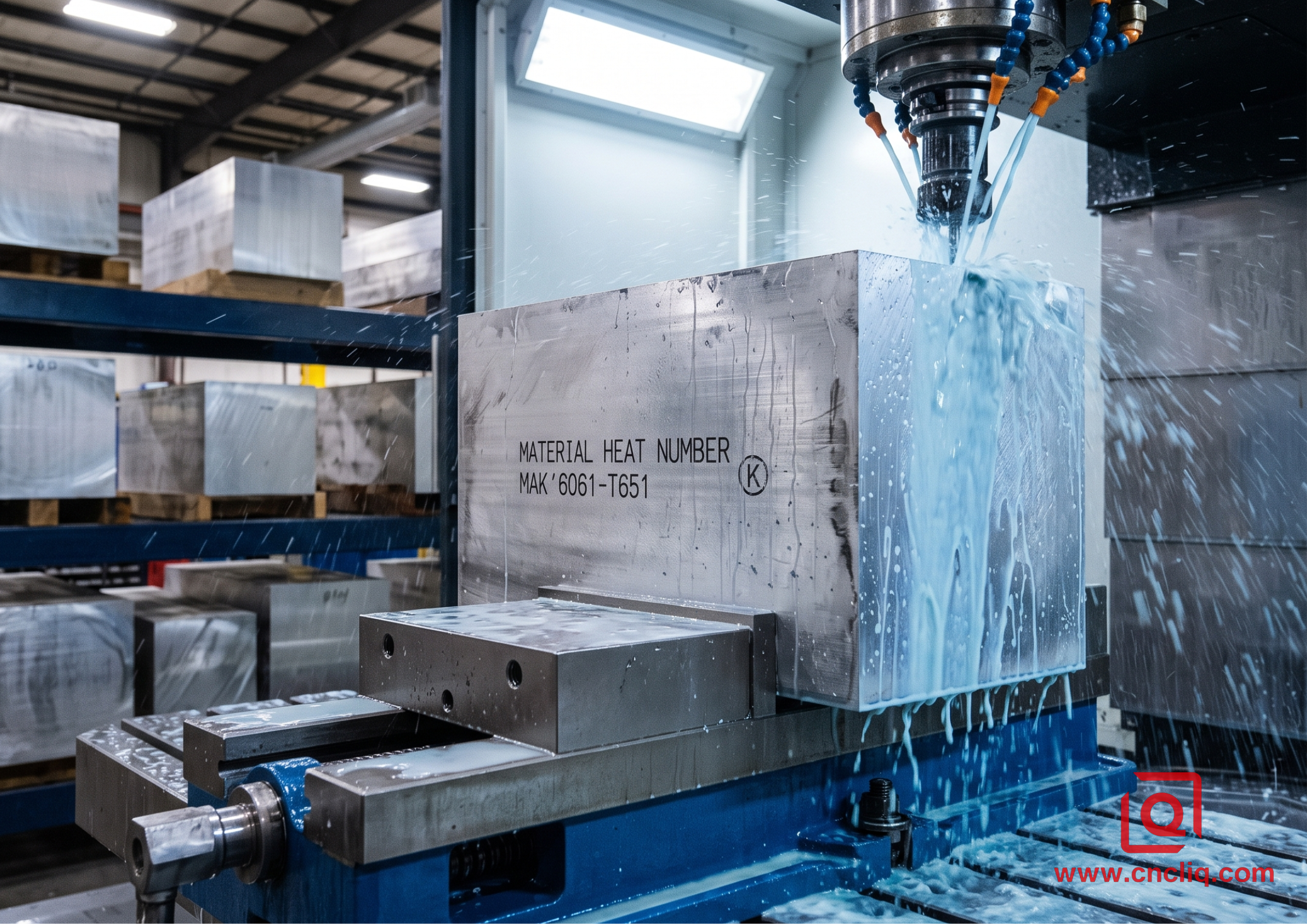
Let's start where most buyers drop the ball: material temper and stress state. Specifying raw 6061-T6 per ASTM B221 without demanding stress-relieved 6061-T651 stock for deep-pocket thin-wall housings is a classic failure mode. When you pocket out 70% of a 50mm-thick billet, residual rolling stresses release non-uniformly. The part bows. Your machine operator spends forty minutes shimming and re-datum layout on a 5-axis trunnion, pushing cycle times through the roof.
Look at the thermal footprint during high-speed roughing. Pushing an uncoated 3-flute carbide end mill at a cutting speed (Vc) of 600 m/min with a feed per tooth (fz) of 0.12 mm/tooth through Al 7075-T651 generates localized temperatures exceeding 280°C at the shear zone. Aluminum’s coefficient of thermal expansion (α≈23×10-6/K) means a 300 mm aluminum sub-chassis expands roughly 0.138 mm under a 20°C delta. If your shop environment fluctuates from 18°C during the night shift to 32°C at 2 PM, and coolant concentration drifts below 7% soluble oil (pH falling under 8.5), you will miss C_pk targets on critical bearing bores.
Shop-floor rule: Lock down your raw material specs. Demand stress-relieved temper (T651/T7351). Enforce 8–10% synthetic emulsion coolant delivered at 70 bar through-spindle pressure to blast chips out of blind cavities before re-cutting causes work-hardening micro-fractures.
DFM Brutal Truths: Pockets, Radius Ratios, and Tool Stickout
Forget aesthetic radii. Internal corner radii (R) govern whether an OEM shop runs a rigid 16 mm solid carbide rougher or has to step down to an extended-reach 4 mm stub mill operating at 15% radial depth of cut (ae).
When designing deep cavities, stick to the L/D ratio threshold:
-
L/D ≤ 3: Standard machining dynamics. High metal removal rates (MRR > 400 cm³/min).
-
L/D > 5: Chatter territory. Tool deflection scales cubically with overhang (δ ∝ L³).
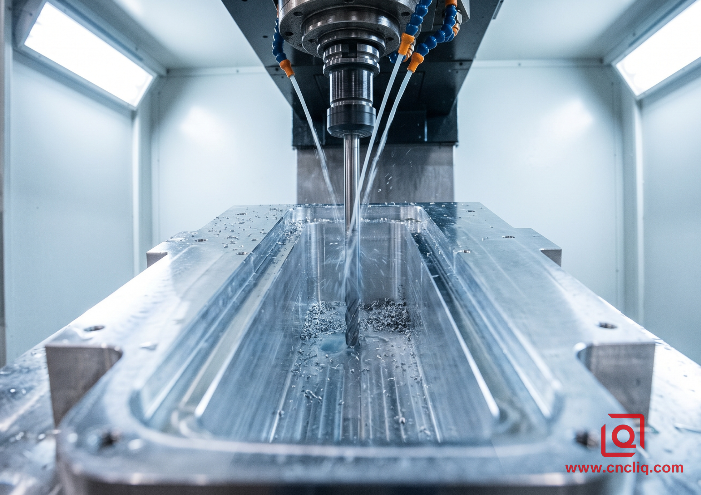
If you specify an internal fillet of R = 3mm on a 40 mm deep pocket, the machinist has no choice. They must select a long-reach end mill with an L/D of nearly 7. To prevent catastrophic chatter and tool breakage, feed rates must be backed off by 60%, turning a 6-minute roughing operation into a 22-minute bottleneck.
Fix it in design:
-
Increase internal corner radii to R = 4.5mm for a 30 mm depth. Allow the cutter to roll around the corner using trochoidal toolpath strategies without burying the tool engagement angle beyond 90 degrees.
-
Standardize wall thickness to minimum 1.8 mm. Thin aluminum walls (< 1.0 mm) act like tuning forks under 12,000 RPM spindle harmonics; unless you want to pay for custom silicone damping fixtures or secondary EDM operations, keep the aspect ratio below 10:1.
-
Replace blind tapped holes with clear-through clearance holes where assembly permits. Tapping 6061-T6 with an M3 thread deeper than 2.5×D in blind holes leads to chip packing; a single snapped thread mill on a finished 5-axis component renders $450 of machining time instantly obsolete.
GD&T Realities: Stop Over-Specifying ASME Y14.5 Callouts
A major driver of bloated OEM unit costs is the misuse of Geometric Dimensioning and Tolerancing (GD&T). Holding positional tolerance of ∅0.02mm at Maximum Material Condition (MMC) across non-mating mounting brackets forces the supplier off a standard vertical machining center (VMC) and onto a temperature-controlled jig borer or high-end 5-axis horizontal machine with optical scales.
Evaluate your drawing tolerances against standard ISO 2768-mK:
-
Holes and Dowels: Keep tight tolerances (± 0.010mm) restricted strictly to dowel locations (H7/g6 fits).
-
Flatness and Parallelism: A 0.05mm flatness spec on a 400 mm milled aluminum plate requires a face mill with wiper inserts, low clamping pressure hydraulic fixtures, and a stress-relief thermal cycle (160℃ for 3 hours) between roughing and finishing. If your part merely bolts to a sheet metal frame, relax that callout to 0.2mm.
-
Surface Roughness: Demanding Ra 0.4μm directly off the machine requires ultra-fine diamond tooling (PCD) or lengthy secondary polishing/fly-cutting passes. Standard high-speed aluminum milling yields Ra 1.6μm to Ra 0.8μm (ASME B46.1)—design for Ra 1.6μm wherever sliding friction isn't present.
Surface Finishing and Anodizing Allowance Calculations
Anodizing is not just paint—it is an conversion process that grows into and builds up on the substrate. A crucial oversight in OEM sourcing is failing to account for dimensional changes caused by MIL-A-8625 Type II (Sulfuric) and Type III (Hardcoat) anodizing.
Type III Hardcoat anodizing typically produces a total film thickness of 50μm(0.050 mm). Crucially, 50% of this thickness penetrates into the raw aluminum surface, while 50% builds up on the outside.
-
External Diameter (Shafts): Increases by 1 × buildup = 0.025mm per side (+0.050mm total on diameter).
-
Internal Diameter (Bores): Decreases by 0.025mm per side (-0.050mm total on diameter).
If your engineer designs an H7 bearing bore (+0.012 / -0.000 mm) and the shop machines it to nominal before sending it to Type III Hardcoat anodizing without masking, the finished bore will arrive 0.038 mm undersized. The bearing won't press in. Your options? Scrap the part or pay for post-anodize precision honing.
Specify clear masking protocols on critical threads and precision bores using silicone plugs or rubber stop-off lacquers. For unmasked critical fit areas, pre-calculate plating growth directly into the CNC offset tables (G54-G59).
The Tactical Buyer's Action Protocol
When sourcing custom aluminum OEM machining services, cost control is a technical discipline, not a negotiation tactic. Execute these five steps on your next RFQ package:
-
Send Native CAD + STEP + PDF with Explicit GD&T: Never send flat PDF drawings alone. Provide 3D STEP files alongside fully dimensioned PDFs indicating critical datum structures (Datums A, B, C).
-
Mandate Material Test Reports (MTRs): Ensure full lot traceability per EN 10204 3.1 certification to avoid low-grade recycled aluminum stock containing silicon inclusions that destroy carbide tooling.
-
Audit Machine Shop Equipment: Match your part geometry to the shop’s spindle torque and RPM profiles. High-velocity aluminum machining thrives on 15,000–24,000 RPM spindles with high dynamic acceleration rates (> 1G).
-
Request DFM Thermal and Fixturing Feedback: Demand that the vendor identify high-risk features (thin floors, deep pockets, tight true position callouts) before quoting.
-
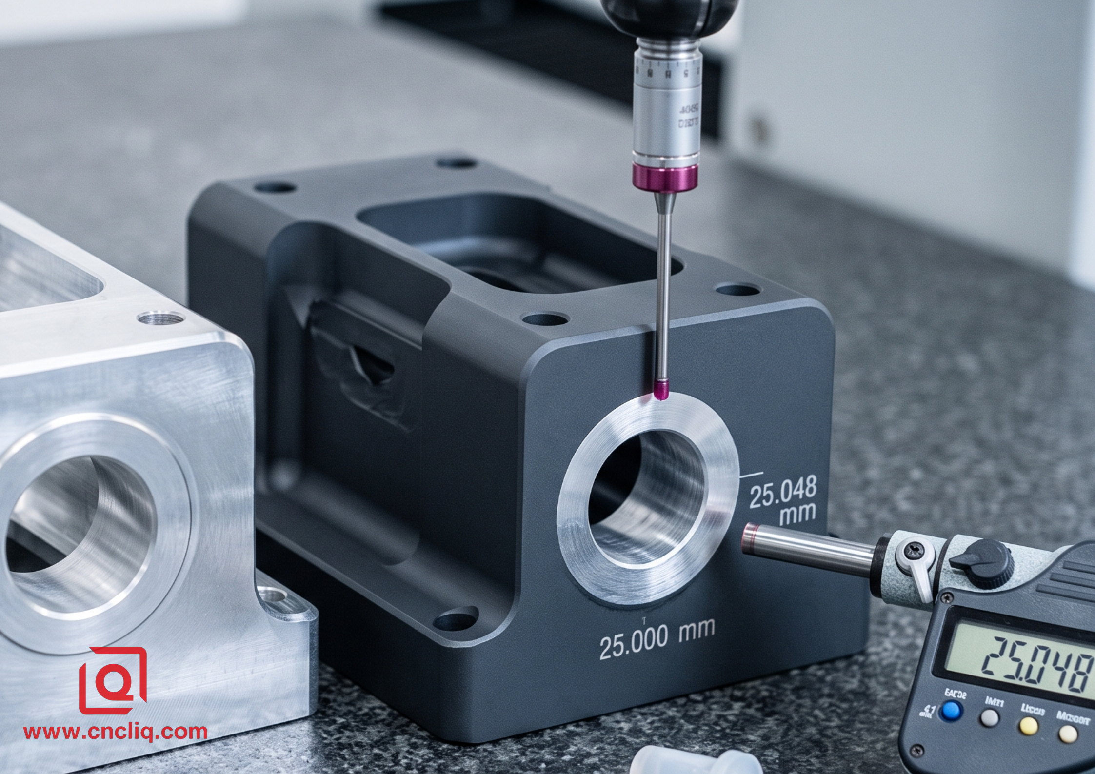
Consolidate Operations: Choose an OEM partner offering integrated CNC milling, multi-axis turning, CMM inspection (ISO 10360-2), and surface finishing under one roof to eliminate freight, markups, and cross-vendor quality disputes.
FAQs
Q1: Why do my custom aluminum parts bow or warp after machining, and how can we prevent it?
A: Warping almost always stems from internal stresses locked inside the metal during raw mill rolling or extrusion. When your CNC cutter carves away the outer layers, those residual forces release unevenly, twisting the component out of shape. You can avoid this by specifying stress-relieved material tempers (such as T651 stock), establishing a staged machining sequence that balances metal removal on opposing sides, or inserting a dedicated stress-relief thermal bake between roughing and final finishing passes.
Q2: Should I request a tight blanket tolerance across my entire part drawing to guarantee quality?
A: Absolutely not. Applying tight blanket tolerances forces machine shops to run conservative cut speeds, schedule repeated tool-wear checks, and potentially move work onto specialized, low-throughput machinery. Instead, leave non-critical cosmetic contours, exterior clearances, and weight-reduction cutouts at relaxed, standard commercial limits, reserving strict callouts exclusively for mating faces, bearing pockets, and critical pin locations.
Q3: How do internal corner radii directly affect my machining lead time and quote?
A: Square or sharp internal corners cannot be cut directly by spinning round carbide tools. Forcing tiny internal corner radii on deep walls forces the machinist to switch to small, fragile, long-reach end mills that must nibble away at the material very slowly to prevent chatter and tool breakage. Designing generous, sweeping internal corner radii allows the factory to use rigid, large-diameter cutters at high feed rates, drastically slashing cycle times and unit costs.
Q4: Is hardcoat anodizing always necessary for industrial aluminum OEM components?
A: Not unless your part experiences aggressive sliding abrasion, high wear, or severe marine or chemical exposure. Standard sulfuric anodizing provides excellent atmospheric corrosion protection, aesthetic uniformity, and electrical insulation at a fraction of the processing complexity. Hardcoat anodizing creates a thick, brittle ceramic-like surface layer that requires careful tolerance compensation and often necessitates masking precision holes to prevent parts from fitting too tightly during assembly.
Q5: What is the most common mistake buyers make when sending drawings for an OEM quote?
A: Relying solely on flat PDF drawings or sending incomplete CAD models lacking clear datum references. A 3D model shows the geometry, but a properly structured engineering drawing tells the machinist which surfaces establish the foundation for inspection and assembly. Providing native CAD files alongside clear, annotated drawings eliminates guesswork, reduces vendor buffer pricing, and speeds up the DFM feedback loop before chip-making begins.
Summary
Custom aluminum OEM machining efficiency depends on optimizing engineering parameters before production begins. High-volume manufacturing costs are driven primarily by raw billet stress states, deep cavity length-to-diameter (L/D) ratios, geometric tolerances, and plating growth during hardcoat anodizing. Aligning raw material specifications (such as stress-relieved T651 temper), generous corner radii, relaxed non-critical tolerances, and precise plating allowances reduces machine cycle times, prevents costly part distortion, and optimizes production costs without sacrificing quality.
Ready to optimize your next manufacturing run? Send us your CAD files to receive a free DFM analysis and an actionable, cost-saving OEM quote from our engineering team within 24 hours.
Contact Information
Disclaimer
Liqin Manufacturing Team
We are Ningbo Liqin Industrial & Trading Co., Ltd.,a professional manufacturer with over 18 years of experience in high-precision custom metal parts. We specialize in CNC machining, forging, die casting, and cold extrusion processes, serving industries such as automotive, medical, aerospace, electronics, and more. Our factory covers an area of 6,500 square meters and is equipped with 150+ advanced machines, including:
- CNC machining centers (4-axis, 5-axis)
- CNC lathes and turning-milling complexes
- Cold extrusion equipment (250T–650T)
- Die casting machines
We adhere to ISO9001, ISO13485: 2016, and IATF16949: 2016 standards, implementing end-to-end quality management: In-process quality control (IPQC), final quality control (FQC), outgoing quality control (OQC). CMM, projectors, hardness testers, and salt spray test equipment. Our products are exported to North America, Europe, Asia, and Oceania. We offer:
- One-stop service from design to delivery
- Quick response within 2 hours for quotes and technical support
- Custom solutions based on your drawings or samples
Welcome your inquiries and samples. Visit our website or contact us directly for a competitive quote!
