 English




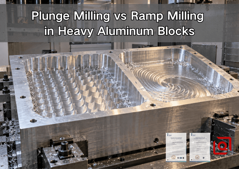
Are you still deciding whether a deep cavity in a heavy aluminum block should be opened by plunging straight down or by feeding the cutter along a ramp? The wrong entry strategy can turn a promising cycle into packed chips, a welded cutting edge, noisy spindle load, or a part that moves after unclamping. This guide explains the choice from the shop floor. It shows what each method really does, how force direction and chip escape change the result, and what information a machining supplier needs before quoting your block.
The short answer is practical. When the pocket provides enough runway, I would usually try a ramp first. The edge can ease into the work while the control keeps the axes moving together. Plunging starts to make sense as the tool gets longer or the cavity becomes restrictive. Its load path gives a marginal setup less reason to bend sideways. Heavy blocks often use both: an approved entry opens working space, plunge passes remove difficult bulk stock, and a ramp or contour strategy leaves consistent material for finishing.
1. Quick Decision Table
|
Shop condition |
Better starting strategy |
Why it usually fits |
Check before release |
|
Wide pocket with enough path length |
Ramp milling |
Smooth entry and continuous engagement |
Maximum ramp angle for the exact cutter |
|
Deep cavity with long tool overhang |
Plunge milling |
More force is directed axially and radial deflection can fall |
Cutter is approved for plunging and chips can leave |
|
Thin ribs or a flexible floor near entry |
Shallow ramp or pre-drilled entry |
Avoids a sudden axial hit beside a delicate feature |
Fixture support and remaining wall thickness |
|
Narrow slot with no room for a helix |
Plunge milling or a drilled access hole |
Fits restricted geometry |
Center-cutting ability, step-over, and evacuation |
|
Open aluminum pocket on a rigid high-speed machine |
Ramp or helical entry into constant-engagement roughing |
Keeps the cutter moving and uses the flute length |
Actual feed through arcs and corners |
|
Very high stock removal from a large billet |
Hybrid process |
Separates stable bulk roughing from controlled wall and floor finishing |
Tool changes, stock allowance, inspection stage |
This table is a starting filter, not a cutting recipe. A tool catalog, machine limits, gauge length, alloy condition, coolant delivery, and the drawing all have veto power.
2. What Plunge Milling and Ramp Milling Actually Mean
Plunge milling removes material through repeated moves that are mainly parallel to the spindle axis. After each plunge, the tool retracts or clears as required, shifts sideways by a controlled step-over, and makes the next axial cut. The floor and wall therefore show a row of overlapping scallops until a later semi-finish or finish pass removes them. A purpose-designed indexable plunge cutter or center-cutting solid carbide tool may be used, but its catalog limits must match the programmed move.
Ramp milling makes axial progress while the cutter also travels laterally. A linear ramp descends along a straight or curved path. A helical ramp descends around a circle and opens a hole or pocket larger than the cutter. Both keep the tool from asking its center to remove all material at once. The method only works when the tool has axial-cutting capability and the path provides adequate clearance.
The important difference is not simply “vertical versus angled.”It is the direction and continuity of the cutting load. Sandvik Coromant’s milling guidance explains that a small entering angle produces a dominant axial force directed toward the spindle, which can stabilize long or weak setups and is why high-feed concepts are used for plunge milling. During a ramp, the edge meets stock progressively instead of all at once. Even so, the force comes back to cutter geometry and the amount of material engaged.
One detail in NIST's Machining of Aluminum and Aluminum Alloys is easy to miss: a tool driven down into solid aluminum needs enough end clearance so its heel does not rub. In plain language, “center cutting”is not a box to assume from appearance. Verify the end geometry and the maker’s approved plunge or ramp data.
3. Why a Heavy Aluminum Block Changes the Decision
A 20 mm plate and a 160 mm billet do not present the same problem. A heavy block stores residual stress and can surround the cutter with a large volume of ductile chips. Deep features also need greater tool projection, increasing leverage at the edge while cavity walls obstruct coolant and chip escape.
Material condition matters as much as alloy name. 6061-T651 and 7075-T651 are common billet or plate choices when strength, machinability, and dimensional stability are required, but “T651” does not make distortion disappear. Removing an unbalanced volume from one side can still release stress. Large cavities should therefore be planned around roughing symmetry, clamp sequence, restaging, and finishing allowance rather than around metal removal rate alone. Our guide to choosing 6061, 7075, or 5052 for CNC milling explains the broader alloy trade-offs.
Chip volume is the second constraint. Aluminum permits high productive cutting speeds with the right tool, so a deep pocket can fill faster than a nozzle clears it. Chips that stay in the cavity are cut again, become hotter and harder to control, and may weld to the edge. The recent guide to 2-flute versus 3-flute end mills for aluminum covers the chip-space decision in detail. For the present comparison, remember one rule: the entry path is not successful if it delivers the cutter into a chip trap.

Controlled radial step-over and an open evacuation path are central to stable plunge roughing.
4. Plunge Milling vs Ramp Milling: The Engineering Trade-Offs
|
Decision factor |
Plunge milling |
Ramp milling |
|
Dominant motion |
Axial, followed by a radial index |
Simultaneous axial and lateral motion |
|
Rigidity advantage |
Useful when long reach makes side loading troublesome |
Useful when the setup supports smooth multi-axis interpolation |
|
Entry space |
Can work in restricted plan area |
Needs ramp length or a valid helical diameter |
|
Chip behavior |
Chips can collect at the bottom unless retract and flushing are planned |
Chips may follow the open path, but a closed helix can still recirculate them |
|
Tool requirement |
Approved plunging geometry; many indexable cutters are not center cutting |
Approved ramp angle and axial cutting geometry |
|
Wall condition after roughing |
Repeated scallops normally need a separate finish pass |
More continuous marks, yet still not a substitute for finishing |
|
Floor condition |
Depends strongly on end geometry and overlap |
Helical or linear witness marks remain unless cleaned up |
|
Machine motion |
Repeated Z moves and controlled lateral indexes |
Coordinated X-Y-Z motion and adequate look-ahead |
|
Best use in heavy blocks |
Deep roughing, limited access, long overhang, weak radial stability |
Entry, open pockets, constant-engagement roughing, thin-feature protection |
|
Main failure mode |
Chip packing, rubbing at the center, excessive step-over |
Excessive ramp angle, low actual feed, corner load, chip recirculation |
The table also explains why the strategies are not competitors in every program. Plunge milling can rough the deep central mass, while ramp milling opens the first cavity and transitions into a constant-engagement path. A later contour pass then controls size and surface finish. This hybrid sequence is often more robust than forcing one tool to enter, rough, and finish everything.
5. Tool Selection: Read the Catalog Before the Cut
For ramp milling, confirm the maximum ramp angle for the exact cutter body, insert, diameter, and corner geometry. Published limits can vary sharply within one product family. Kennametal’s Mill 1-10 data, for example, lists different maximum ramp angles as cutter diameter changes; that is evidence against using a universal “safe”angle. Sandvik’s data for one specific 66 mm CoroMill 390 body lists a 1.8 degree maximum ramp angle and a 1.5 mm maximum plunge depth. Those figures belong to that catalog item, not to every aluminum cutter.
For plunge milling, ask whether the tool can cut at center or only plunge with partial radial engagement. Many indexable milling bodies have a non-cutting center. Driving such a tool straight into solid stock can leave a core, overload the body, or cause interference. The practical answer may be a pilot hole, an off-center start, or a different cutter.
For a solid-carbide option, I first look at edge sharpness, flute polish, chip space, and how much core remains at the required reach. Follow the maker's coating recommendation. Keep gauge length only as long as access demands, clean the holder, and measure runout near the edge; otherwise one tooth may carry most of the load.
Use coolant or air to carry chips out of the cut, not merely to wet the holder. Deep cavities often need a nozzle orientation that changes as the pocket opens. If through-tool coolant is available and approved for the cutter, it can improve delivery at depth. If it is not, the program may need retracts, a staged cavity, or an access channel that lets chips escape.
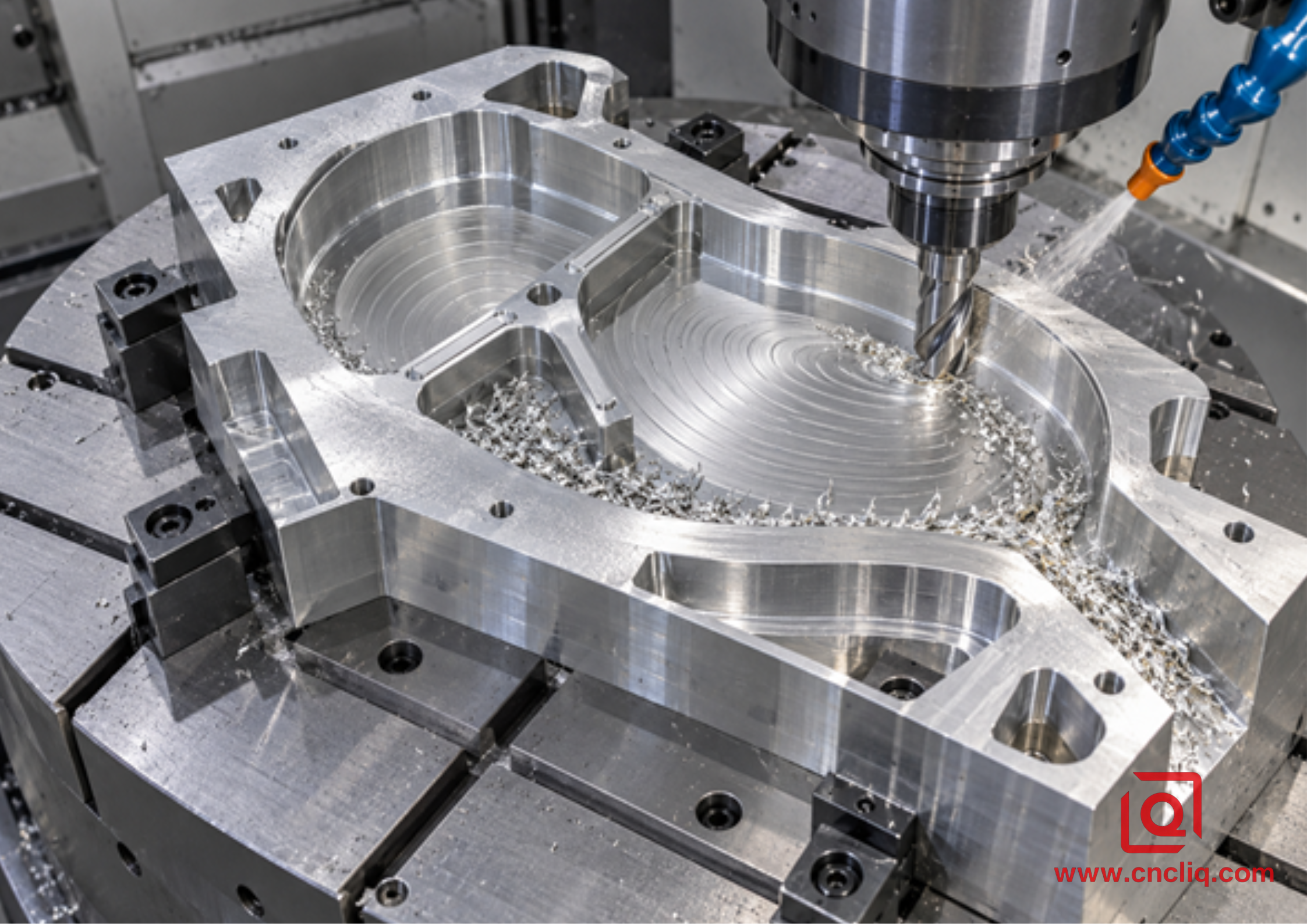
A visible helix is only part of the answer; the tool must be approved for the angle and chips still need an exit.
6. Speeds, Feeds, Ramp Angle, and Step-Over Without Guesswork
Start from the cutter maker’s data for the alloy and operation. Then translate it with the standard milling relationships used throughout the industry:
Spindle speed: n = (1,000 × Vc) ÷ (π × D)
Table feed: Vf = n × z × fz
Material removal rate: Q = ap × ae × Vf ÷ 1,000
Here, Vc is cutting speed in m/min, D is effective cutter diameter in mm, n is spindle speed in revolutions per minute, z is the number of effective teeth, fz is feed per tooth in mm, ap is axial engagement in mm, ae is radial engagement in mm, and Q is removal rate in cm³/min.
Consider an illustrative side-cut calculation for a 20 mm, three-flute cutter at 300 m/min and 0.10 mm/tooth. The equations give about 4,775 rpm and 1,433 mm/min. That arithmetic does not approve a plunge feed, ramp angle, axial depth, or radial step-over. It only checks that speed and feed are internally consistent. A catalog-specific axial feed or ramp correction must still be applied, and the machine must be able to maintain the programmed feed through the real path.
Ramp angle is a tooling limit, not a stylistic CAM setting. A shallow angle lengthens the path; a steep one can overload end edges or cause body interference. Helical diameter also matters because a non-center-cutting tool needs enough orbit to clear its center. That catalog maximum marks the boundary; it is not where a cautious prove-out has to begin.
On a plunge cycle, the sideways index decides both the fresh bite and the cusp left behind. Too much step-over raises radial load and can defeat the stability advantage. Too little may create excessive strokes, rubbing, and long cycle time. Set it from the tool maker’s plunging guidance, then prove the cut while watching load, chip shape, sound, edge condition, and the scallop pattern.
For a broader calculation workflow, see our 6061 aluminum speeds and feeds guide. When high removal rate is the main commercial target, the article on high-speed machining of aluminum OEM parts explains why nominal MRR must be balanced against real machine motion, holder security, and scrap risk.
7. A Shop-Floor Selection Workflow
1. Read the drawing before choosing a toolpath. Mark deep pockets, thin floors, sealing faces, datum relationships, internal corner radii, and surfaces that cannot carry plunge cusps.
2. Confirm stock form, alloy, and temper. Include the material certificate requirement on the RFQ when traceability matters.
3. Map tool access. Compare pocket depth, corner radius, holder clearance, and the shortest usable gauge length. If the holder collides, the nominal cutter diameter is irrelevant.
4. Check the machine. Check what the machine can really support: torque at speed, Z behavior, control look-ahead, coolant reach, fixture stiffness, and chip handling.
5. Select an entry that the tool explicitly supports. Use a drilled access hole when it is safer and does not conflict with the design. Do not assume every end mill can drill.
6. Plan chip travel. Decide where chips will go after the first, tenth, and final roughing pass. Open a channel early when geometry allows.
7. Separate roughing from finishing. Leave even stock on critical walls and floors. Use a fresh or controlled edge for the final pass when size, sealing performance, or appearance matters.
8. Prove a controlled first-off part. Write down spindle load, segment time, chip condition, edge wear, movement after release, and inspection results. When tuning starts, move only one lever per trial.
This process is also valuable during sourcing. A supplier who asks about tolerance zones, free-state inspection, finish allowance, and annual quantity is estimating process risk, not delaying the quote. If your block has multi-face features, our multi-axis CNC milling guide for complex aluminum parts shows how setup count and tool reach interact.
8. Anonymous Customer Case: Hybrid Roughing for a Robotics Fixture Base
The following anonymized composite case is an engineering example based on Liqin’s published custom aluminum machining capabilities. It is not a promise that the same figures apply to another drawing.
A European automation integrator requested a 6061-T651 robotics fixture base from a 620 × 420 × 160 mm block. Three pockets reached 108 mm deep, with vacuum passages, narrow bridge ribs, and datum-related dowel bores. About 56 percent of the stock volume had to be removed while controlling free-state flatness, bore position, and internal cleanliness.
The first CAM concept used one long-reach end mill for helical entry and pocket clearing. The helix fitted, but deep cutting held the tool at excessive gauge length while chips circulated below the ribs. Short moves also reduced actual feed and encouraged rubbing.
The revised process used a hybrid plan. A short tool opened two broad access zones with shallow helical ramps. A purpose-approved indexable plunge cutter then removed the deepest central stock in offset rows while the pocket was still stiff. The program opened a chip escape channel before completing the enclosed region. Semi-finishing restored even allowance, the clamps were relaxed and the part was re-referenced, and separate finishing tools completed the datum floor, rib walls, and bores. Cross passages were deburred and cleaned before inspection.
During the illustrative pilot comparison, peak spindle load in the deep roughing segment moved from approximately 82 percent to 61 percent, and roughing time moved from 74 minutes to 58 minutes. Those results came from the complete process change, not from plunge milling alone. The important commercial outcome was a repeatable route: roughing stability improved, the finishing allowance became more uniform, and inspection could focus on the features that controlled assembly.
The part type is closely related to Liqin’s published precision aluminum manifold machining, where multi-face ports, deep holes, deburring, cleaning, and dimensional verification must be planned as one manufacturing system. For your own RFQ, send the STEP model and controlled drawing rather than asking for a price from overall dimensions alone.
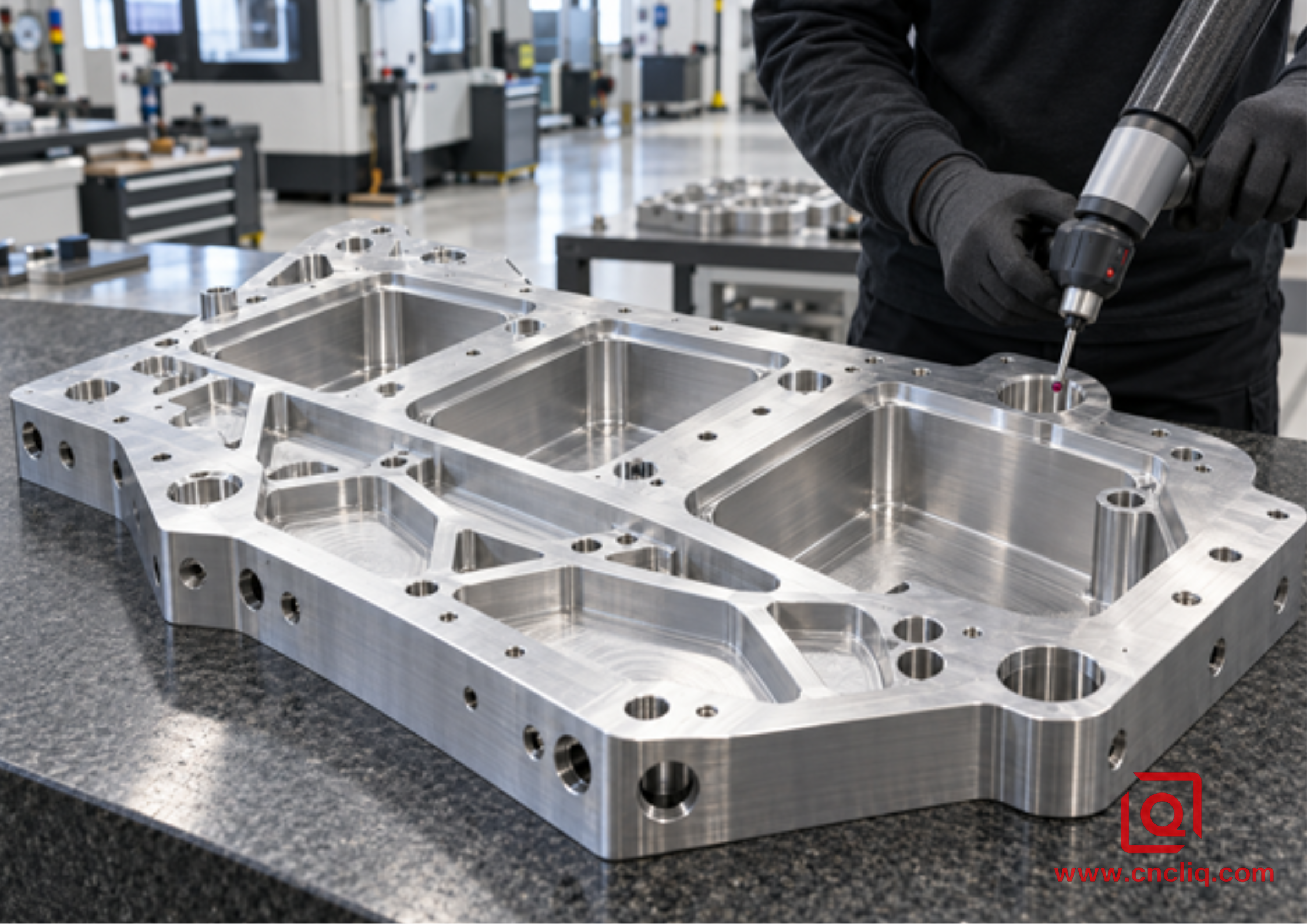
The cutting strategy is complete only after free-state geometry, critical bores, and internal cleanliness are verified.
9. Common Failure Modes and First Checks
|
Symptom |
Likely mechanism |
First checks |
|
Aluminum welded to the center of the tool |
Non-center-cutting geometry, rubbing, or weak lubrication |
Stop and inspect the end geometry; verify axial capability and real feed |
|
Sudden load spike during a ramp |
Ramp angle, corner engagement, or body interference is too high |
Compare the programmed path with catalog limits and CAM engagement |
|
Chatter deep in the pocket |
Excessive gauge length, radial load, weak fixture, or chip recutting |
Shorten the assembly, reduce radial engagement, improve evacuation |
|
Rows of heavy cusps after plunging |
Step-over is too large or no semi-finish allowance was planned |
Reduce step-over within tool guidance and schedule a cleanup pass |
|
Gray or smeared wall |
Built-up edge, runout, dull edge, or rubbing in short moves |
Inspect the edge and holder; verify actual feed, not only commanded feed |
|
Pocket fills with chips |
No clear exit, poor nozzle direction, or long uninterrupted cut |
Open an escape path, redirect delivery, and add controlled clearing moves |
|
Part bows after unclamping |
Residual stress release or unbalanced stock removal |
Review temper, rough both sides where possible, restage, then finish |
|
Floor or bore misses size after a good roughing cycle |
Finish stock is uneven or the roughing tool is being asked to finish |
Separate tools and passes; measure before applying compensation |
Do not cure every alarm by reducing feed. A slower feed at the same rpm can make an aluminum cutter rub and build heat. Inspect the chip, edge, actual motion, and engagement first. Our article on controlling built-up edge in aluminum discusses the underlying adhesion mechanism, even though its main operation is turning.
10. What to Send for a Reliable Heavy-Aluminum-Block Quote
· Native 3D model, preferably STEP, plus the controlled 2D drawing
· Alloy, temper, stock form, and material certification requirement
· Critical tolerances, datums, GD&T, surface roughness, and free-state inspection condition
· Pocket depths, minimum internal radii, inaccessible features, and any no-cusp surfaces
· Surface treatment, masking zones, threaded inserts, cleaning, and packaging requirements
· Prototype quantity, annual volume, batch size, target delivery, and destination
· Functional context such as sealing, vacuum, alignment, fatigue, or cosmetic requirements
These details let the manufacturing engineer decide whether ramping, plunging, pre-drilling, adaptive roughing, or a hybrid route gives the best risk-adjusted cost. They also prevent a low initial quote from growing after the tool-access and inspection requirements become visible. Send Liqin your model and drawing for a process-aware review. We can identify risky entry zones, propose practical radii or stock allowances, and return a quotation tied to the geometry you actually need.
FAQ
1. Is plunge milling always faster than ramp milling in a heavy aluminum block?
No. Plunge milling can stabilize deep roughing when radial rigidity is poor, but repeated retracts and indexes add motion, and the resulting scallops need cleanup. Ramp milling may be faster in an open pocket on a rigid machine because it transitions directly into constant-engagement cutting. Compare the complete cycle, including chip clearing, tool changes, finishing, and inspection rather than comparing only the first entry move.
2. Can any center-cutting end mill plunge straight into aluminum?
Not safely by assumption. Center-cutting means the end geometry can cut across the center, but it does not define the approved axial feed, depth, chip evacuation, or suitability for a deep blind cavity. Check the exact tool maker’s data, end clearance, gauge length, and coolant path. A drilled access hole or helical entry may still provide a more reliable process.
3. What ramp angle should I use for aluminum?
There is no universal angle. Maximum ramp angle changes with cutter family, diameter, insert geometry, corner radius, helix diameter, and body clearance. Use the catalog value for the exact assembly as a ceiling, then select a conservative proof-cut setting that fits the machine and pocket. If the path is very long, balance the lower load of a shallow angle against extra cycle time and possible rubbing.
4. Which method gives the better pocket finish?
Neither roughing method should be treated as the final finish by default. Plunge milling leaves overlapping cusps, while ramp milling can leave helical or linear witness marks. Critical walls, sealing floors, and dowel bores normally need a controlled semi-finish and finish pass with uniform allowance, measured runout, suitable lead-in and lead-out, and verified chip control.
5. How can a buyer reduce the quotation risk for a large aluminum block?
Provide the STEP model, controlled drawing, alloy and temper, critical features, free-state inspection condition, required reports, prototype quantity, and annual volume. Mark functional surfaces instead of applying tight tolerances everywhere. This lets the supplier choose realistic tool access, roughing strategy, restaging, finishing, and inspection before pricing, which is far more reliable than quoting from an overall size and a screenshot.
Summary
Plunge milling and ramp milling solve different problems in heavy aluminum blocks. Ramp milling is a strong first choice when a suitable cutter has space for a smooth descent and the machine can maintain coordinated motion; plunge milling becomes valuable when depth, overhang, restricted access, or weak radial rigidity dominates. The most reliable production route is often hybrid: open the cavity safely, direct roughing forces where the setup is strongest, create a real chip exit, leave even finish stock, and verify the part after stress release. Tool-maker limits, the drawing, and a controlled first-off trial must govern every speed, angle, depth, and step-over.
Contact Information
Company: Ningbo Liqin Industry Co., Ltd.Daily customer maintenance & after-sales support:service@shturl. zhuwanying@cncliq.com
New inquiry, quotation & order discussion:business@shturl. zhouli@chinaliqin.com
Hotline: +86 18757148656
Disclaimer
All technical articles, material specifications, machining recommendations, and surface treatment details published on this blog are for informational and reference purposes only. Please note that general blog insights do not replace signed technical agreements. Because custom parts vary by material heat numbers, machine calibrations, and specific tolerances, binding quality specs are governed solely by your approved CAD drawings, signed contracts, and formal quality plans.
All customer case studies featured on this blog have been thoroughly anonymized and sanitized. The performance metrics, manufacturing workflows, and imagery displayed serve solely to demonstrate our custom machining capabilities and do not represent a single universal standard for all orders.
Liqin Manufacturing Team
Built on 18 years of precision engineering experience, Ningbo Liqin Industry manufactures high-tolerance metal components for demanding global markets. We operate out of a 6,500 m² production hub equipped with over 150 machines, running 4-axis and 5-axis CNC machining, mill-turn machining, cold extrusion, and pressure die casting under one roof. This setup allows us to manage projects seamlessly, taking parts from initial CAD concepts directly to finalized shipments.
We handle quality control with zero compromise. We treat tight tolerances with the engineering discipline they require. Backed by ISO 9001, ISO 13485, and IATF 16949 certifications, our QA engineers run strict IPQC, FQC, and OQC checks on every single production batch. From CMM dimensional mapping and optical profiling to hardness and salt-spray testing, we validate your critical specs upfront—so you receive drop-in ready components with zero assembly headaches or costly line stoppages. On top of manufacturing, you can rely on us for two-hour response times on new RFQs, direct support for prototype sampling, and smooth export shipping across Europe, North America, Asia, and Oceania.
Welcome your inquiries and samples. Visit our website or contact us directly for a competitive quote!
