 English




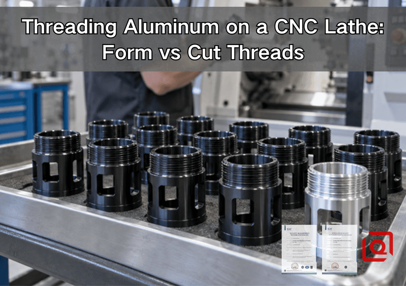
Are you still losing time to packed chips, torn thread flanks, or a plug gauge that stops halfway into an aluminum part? The thread may look like one small drawing feature, yet it can decide whether a valve seals, a sensor cap assembles, or an entire batch waits for rework. This guide explains form threads versus cut threads from the shop floor. You will see where each method fits, what changes on a CNC lathe, and what information lets a supplier quote the job without hiding process risk inside the price.
Short answer: Use cut threading when the geometry, alloy, batch size, thread standard, or low forming ductility demands flexibility. Consider form threading when the aluminum is suitably ductile, chip-free production matters, the pilot diameter can be controlled closely, and the quantity justifies dedicated tooling. Neither method wins every drawing. The reliable choice comes from the complete tolerance chain: material condition, thread size, wall thickness, engagement, finishing, inspection, and assembly duty.
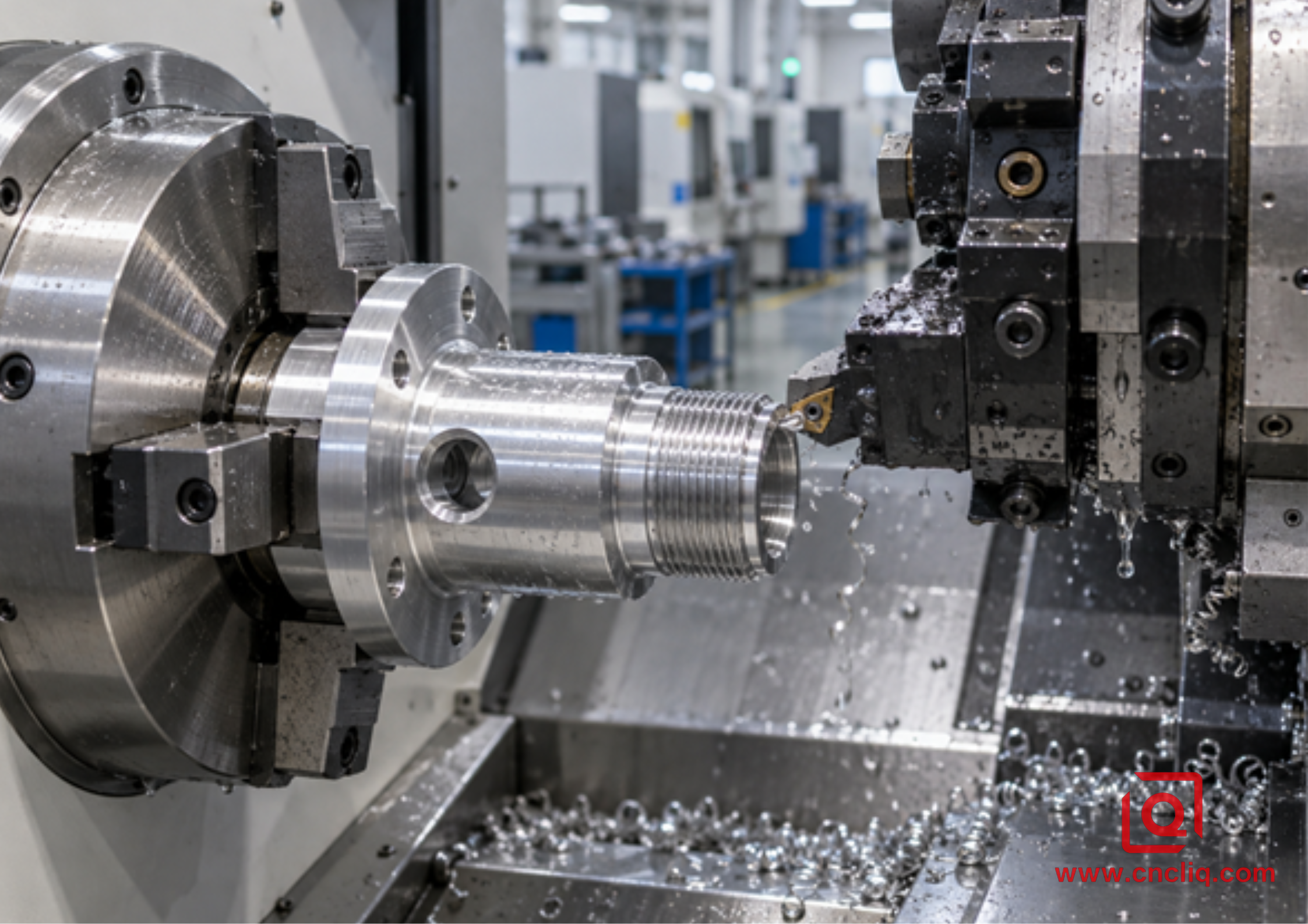
CNC lathe threading of a flanged aluminum sensor housing.
Quick Decision Table: Form or Cut?
|
Decision factor |
Cut thread |
Form thread |
|
How the profile is made |
Material is removed by a tap, die, chaser, or single-point insert. |
Ductile material is displaced under pressure; no thread chips are created. |
|
Best production fit |
Prototypes, mixed standards, large or unusual profiles, thin walls, and lower volumes. |
Repeat production in formable aluminum with stable holes, rigid alignment, and strong lubrication. |
|
Chip behavior |
Chips must be broken, directed, and evacuated. |
Chipless at the thread-forming operation. |
|
Tooling flexibility |
High; single-point and partial-profile tools cover many diameters or pitches. |
Lower; tool and pre-hole are closely tied to size and material response. |
|
Pre-thread diameter |
Cut-tap drill or turned minor diameter leaves stock to be removed. |
Larger, more tightly controlled pre-hole because metal must flow into the crest. |
|
Torque and pressure |
Depends on sharpness, chip load, friction, and evacuation. |
Forming torque and radial pressure are generally higher. |
|
Main risks |
Bird-nesting, built-up edge, chipped insert, tap breakage, flank tearing. |
Wrong pilot size, high torque, lube failure, thin-wall growth, crest laps. |
|
Lathe routes |
Single-point turning, rigid tapping, self-opening die head. |
Internal form tapping; external rolling with a suitable head or attachment. |
|
Inspection |
GO/NO-GO gauge plus drawing-specific checks. |
The same gauging, with closer control of pre-hole and forming torque. |
1. First, Define “Form Thread” Correctly
The wording causes confusion because “thread form” can also mean the geometric shape of any thread. Here, a formed thread means a profile made by plastic displacement instead of chip removal. An internal form tap has lobes but no cutting flutes. It presses the pre-hole wall into the root and crest. An external rolling head uses dies to displace the outside diameter into a thread.
A cut thread removes metal. On a lathe that may mean a single-point insert synchronized to the spindle encoder, a tap held on centerline, a die head, or a multi-tooth chaser. For single-point work, Z-axis feed per spindle revolution equals thread lead. On a single-start M20 × 2.5 thread, the programmed feed is 2.5 mm/rev. A multi-start thread uses lead, not pitch, so the programmer must not treat those terms as interchangeable.
This distinction matters during quotation. “CNC threaded” does not reveal whether the supplier plans to tap, single-point, roll, or mill the feature. If function depends on fatigue, sealing, repeated assembly, or post-anodize fit, ask for the proposed method and inspection plan.
2. What a CNC Lathe Changes
A CNC turning center holds rotational features to one spindle axis. That is valuable when a thread must run true to a pilot, seal land, bore, or face. The encoder synchronizes spindle angle with Z motion on every cutting pass. Successive passes therefore follow the same helix instead of carving a second path.
For a concentric housing, the strongest process plan is often to finish the datum bore, sealing face, pilot diameter, relief, and thread before releasing the chuck. When radial ports or backside features share the same tolerance chain, a turn-mill or twin-spindle route may reduce re-clamping error. Our guide to CNC turning versus turn-mill machining for concentric aluminum housings explains that decision in more detail.
The lathe does not remove the basic risks. Aluminum can weld to a dull edge. A long chip can wrap around a finished diameter. A slender boring bar can vibrate inside an internal thread. A form tap can expand a thin boss. Good threading still begins with rigid workholding, low runout, short tool overhang, clean coolant delivery, and enough clearance for safe entry and retract.
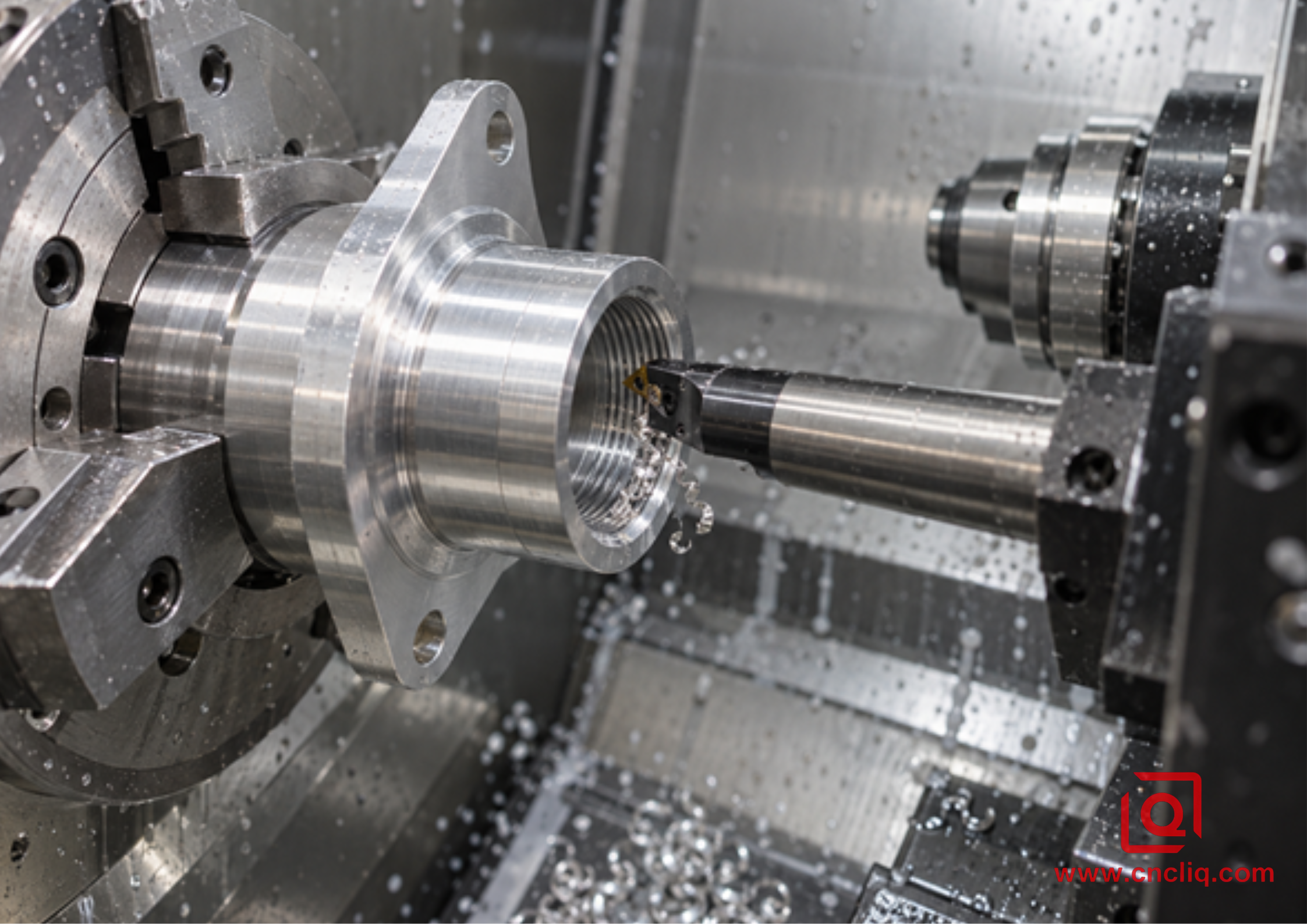
Internal single-point cutting keeps the thread concentric with the turned bore and face.
3. Cut Threads: Flexible and Honest About Geometry
Single-point cutting is the lathe’s most adaptable route. One holder can accept full-profile inserts for a specific pitch or partial-profile inserts that cover a pitch range. Full-profile inserts generate the root and crest together and usually simplify gauge control. Partial-profile inserts are useful for mixed work, but the machinist must control the prepared major diameter and avoid leaving an incorrect crest.
The usual sequence is direct: turn the major or minor diameter, add an entry chamfer, machine a runout relief if the design allows it, confirm the insert profile, and cut several synchronized passes of decreasing depth. A final no-load or light spring pass may clean elastic recovery, but repeated spring passes should not hide chatter, tool deflection, or an incorrect programmed depth.
Cut threading earns its place in 5 situations:
1. Large or nonstandard threads. A single-point insert is easier to source or customize than a dedicated forming tool for an unusual diameter, pitch, taper, or profile.
2. Thin walls. Cutting creates lower radial forming pressure, so it is often safer for lightweight sleeves and bosses that could grow or ovalize.
3. Short runs and prototypes. Flexible tooling avoids a dedicated rolling head or form tap for a design that may change after testing.
4. Less-ductile stock. High-silicon cast aluminum and other low-elongation materials may crack, flake, or fill poorly when displaced.
5. Controlled external geometry. Single-point turning makes it practical to relate thread pitch diameter, shoulder, seal groove, and datum diameter in one setup.
Internal cut taps are fast, but the flute style must fit the hole. A spiral-point tap pushes chips forward and needs space beyond a through hole. A spiral-flute tap draws chips back from a blind hole. Bottom clearance, drill-point depth, chamfer length, and usable thread length are separate dimensions; collapsing them into one depth callout is a common drawing error. The aluminum deep-hole drilling and rigid tapping guide covers that relationship.
4. Form Threads: Chipless, Fast, but Less Forgiving
Form tapping can remove the chip-control problem from internal threading. That is a major advantage in blind holes, small threads, and clean fluid components where one loose chip can block a passage. Because the lobes displace metal, the formed flank follows the material flow and receives local cold work. This can improve resistance to stripping or fatigue in a suitable alloy, but it is not a blanket promise that every formed thread is stronger. Pilot diameter, percentage of thread, alloy temper, wall support, lubrication, and mating fastener all influence the result.
Forming starts with a larger pre-hole than cut tapping. Guhring’s published tapping formulas express the difference clearly: a general metric cut-tap starting drill is approximately basic major diameter minus pitch, while a metric form-tap starting drill is approximately basic major diameter minus half the pitch. Using those general formulas, M6 × 1.0 starts near 5.0 mm for cutting and 5.5 mm for forming. These are teaching values, not production release dimensions. The selected tool maker’s chart, tolerance class, actual hole process, material lot, coating, and trial results take priority.
That larger pilot has a narrow job: leave enough metal to fill the crest without pushing torque beyond a safe window. Too small and the tap must displace excessive material, raising torque and risking galling, tool failure, or boss expansion. Too large and the crest may be incomplete, reducing effective engagement. Drill runout and bell-mouth can therefore become thread defects even when the tap is perfect.
Form tapping needs lubricant that survives high contact pressure. A thin coolant film that works for general turning may not prevent aluminum pickup on the lobes. Through-tool delivery, concentration, and cleanliness should be validated on the actual machine. A stable holder must keep the tap centered and parallel; misalignment makes one lobe carry more load and can produce an oversize, tapered, or rough thread.
External thread rolling follows the same displacement principle but demands a suitable rolling head, enough wall or core support, a prepared blank diameter, and clearance around shoulders. It can be highly productive in repeat work. It is not automatically suitable for a delicate hollow sleeve simply because the alloy is aluminum.
5. Alloy and Temper Decide How the Metal Behaves
“Aluminum” is not a process specification. Wrought 6061-T6, 6082-T6, and 7075-T6 behave differently from a high-silicon die casting. Even within one nominal grade, stock form, temper, heat history, and lot condition influence chip shape and formability.
6061 is a common starting point because it balances availability, machinability, corrosion resistance, and finishing response. It often supports cut or form threading when the geometry is sound. 6082 is widely used for structural parts and can also be a candidate, subject to validation. 7075 offers higher strength but may require a more conservative forming assessment, especially at sharp roots or thin sections. Cast alloys need particular care: silicon content and porosity can make displacement less predictable, while interrupted hard particles influence cut-tool wear.
Before locking the method, confirm exact alloy, temper, raw-stock route, and post-machining treatment. If material is undecided, use the OEM aluminum CNC turning alloy guide. For 6061-specific tool and chip considerations, see how to machine 6061 aluminum.
6. Build a Process Window, Not a Universal Speed
It is tempting to ask for one spindle speed and one pass schedule. A responsible shop asks more questions first: diameter and pitch, tool grade and coating, internal or external cut, overhang, coolant route, acceleration, encoder performance, wall stiffness, and whether the thread stops at a shoulder.
· Metric tapping RPM: RPM = cutting speed in m/min × 1000 ÷ (π × tool diameter in mm).
· Inch tapping RPM: RPM = cutting speed in sfm × 3.82 ÷ tool diameter in inches.
· Single-start feed: feed per revolution equals pitch.
· Multi-start lead: lead equals pitch multiplied by the number of starts.
Cutting speed must come from the tool maker’s data for the actual alloy and tool. Start within that published window, then prove torque, chip shape, flank finish, gauge result, and tool life on the machine. A glossy flank is not enough. Aluminum can smear or burnish while pitch diameter remains wrong.
For single-point cutting, infeed strategy changes chip load. Radial infeed loads both flanks and is simple for fine pitches. Modified flank infeed can improve chip direction on coarser profiles. The CNC cycle should reduce depth as the groove widens so each pass removes a manageable area. G76 syntax varies by control generation; copying an example without checking the machine manual is a preventable way to crash into a shoulder. Sandvik Coromant’s Threading Application Guide is an authoritative reference for method, infeed, tool choice, and cutting-data logic.
7. DFM Details That Prevent Expensive Surprises
Provide a real runout strategy
A thread ending against a face needs room for tool deceleration and retract. If no relief groove is allowed, the supplier may need a slower pull-out, a shorter insert, another cycle, or another process. Show the functional last full thread and permitted undercut instead of asking the programmer to guess.
Separate usable thread from hole depth
On a blind internal thread, specify usable full-thread depth, pilot depth, drill-point allowance, and bottom-wall requirement. A tap cannot produce a complete profile through its chamfered lead, and chips from a cut tap need somewhere to go. Extra depth adds reach, friction, cycle time, and breakage risk.
Support thin walls
Forming pressure can enlarge a boss or print through a thin tube. Cutting pressure and chuck force can also distort the feature. Keep the thread near a supported section where possible, or let the supplier evaluate a mandrel, softer jaw pressure, and a sequence that measures the part after release.
Control the entry and burr
A small chamfer guides the tool and removes the fragile first crest. An aggressive chamfer can shorten engagement. Define its size, not merely “break edge,” when sealing or engagement starts near the face. Burr control matters at cross holes: a thread intersecting a radial port can leave a fragment in a fluid path.
Plan for anodizing before cutting metal
Anodizing changes surfaces, edges, and thread fit. The response may be masking, pre-process compensation, post-finish chasing where allowed, or another tolerance strategy. Do not apply a generic thickness offset without agreement among design, machining, finishing, and inspection. Our clear versus black anodize DFM guide explains why coating type, thickness, color, and masking belong on the RFQ.
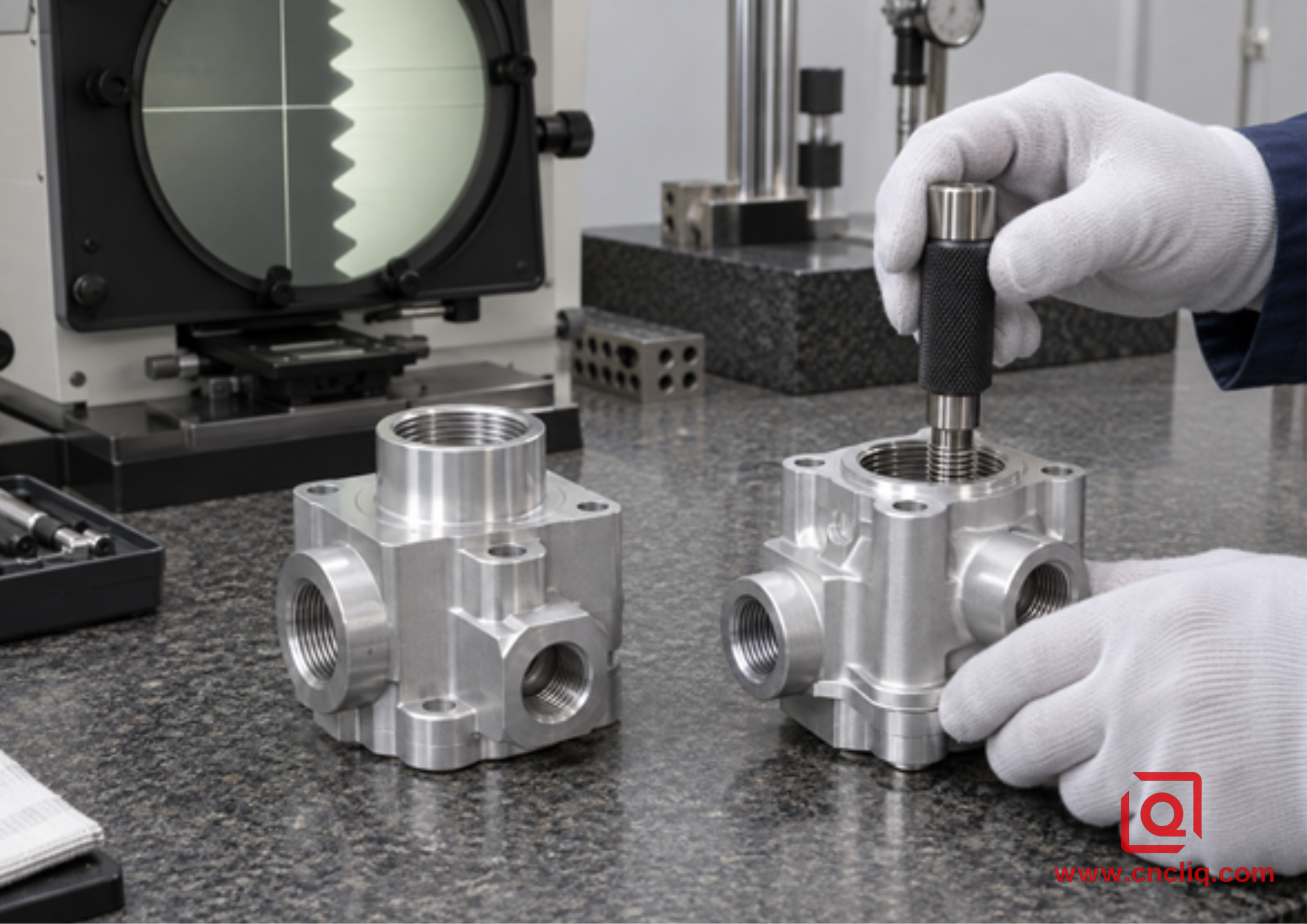
Functional gauging must follow the drawing datum and finishing condition.
8. Troubleshooting by Evidence
|
Symptom |
Likely causes |
Shop-floor checks |
|
Cut thread tears or looks gray |
Built-up edge, dull edge, poor lubrication, rubbing, unstable bar. |
Inspect the edge; check speed, overhang, runout, and coolant aim. |
|
Gauge starts but binds deeper |
Tapered pre-hole, misalignment, wear, chip packing, thermal drift. |
Measure pre-hole by depth; verify alignment, gauge temperature, and chips. |
|
Form-tap torque rises suddenly |
Pre-hole too small, lube failure, material-lot change, lobe pickup. |
Stop before breakage; log torque, measure holes, inspect tool, confirm alloy. |
|
Thread is oversize after release |
Thin-wall distortion, high chuck pressure, radial forming load. |
Gauge free state; compare clamped and released geometry; review support. |
|
External thread chatters |
Overhang, weak support, wrong infeed, poor synchronization. |
Shorten stickout; check support, encoder alarms, insert seating, and passes. |
|
Gauge fails after anodize |
Coating buildup or poor masking control. |
Agree pre/post-finish gauging, mask limits, and pitch-diameter strategy. |
Troubleshooting should connect one symptom to one measured cause. Changing speed, coolant, hole size, and tool at once may make the next part pass, but it does not establish a repeatable process.
9. Inspection: Prove Function, Then Trace the Process
A mating screw is an assembly sample, not a calibrated thread gauge. Use the specified GO/NO-GO plug or ring gauge for functional acceptance, with gauge class and inspection condition agreed in advance. For critical threads, add checks appropriate to the drawing: pitch diameter, optical profile, lead or taper, concentricity to datum, and surface condition at sealing regions.
Form-thread control starts one operation earlier. Record pre-hole diameter and, where risk justifies it, forming torque. Cut-thread control adds chip condition and tool-wear limits. Both routes need first-article approval and a sampling plan tied to batch size, tool changes, and criticality. If anodizing follows, define whether acceptance is before finish, after finish, or both.
Liqin’s precision aluminum manifold combines threaded ports, blind holes, cross-channels, datum faces, cleaning, and functional inspection. The 6061-T6 lightning-arrester housing shows another verified route: a cold-extruded blank followed by precision machining, a 5/16-18 Whitworth threaded feature, deburring, cleaning, and gauge inspection. These pages do not establish universal tolerances; they show why thread production must stay connected to material, datum scheme, and end use.
Anonymized Customer Case: A Sensor Sleeve With a Blind Internal Thread
The following is a sanitized composite case used to explain process selection; identifying details and commercial data are intentionally omitted.
An automation-equipment customer requested a 6061-T6 sensor sleeve with a concentric locating bore, an O-ring face, 3 radial windows, and a blind M12 × 1.5-6H rear thread. The cap would be removed during scheduled maintenance, while the internal cavity had to remain free from loose chips.
The quotation review considered single-point cutting, a spiral-flute cut tap, and a form tap. Single-point cutting offered excellent control but required a small internal bar with clearance near the blind end. The cut tap shortened cycle time, yet still created chips beside a finished sealing cavity. Form tapping removed that chip source, but the team first had to verify wall support, pre-hole capability, lubrication, and condition after black anodizing.
The trial route turned datum bore, face, pilot hole, and chamfer in one chucking. A controlled pre-hole was finished after rough turning so chucking stress and heat had less influence on size. The form tap ran in a synchronized holder with directed lubricant. Parts were cleaned, gauged in free state, anodized with the thread protected according to the approved plan, and gauged again. A cut-thread contingency remained for prototypes and any future alloy change.
The commercial lesson mattered more than the tool. The RFQ became quotable only after the customer defined usable engagement, blind-hole bottom allowance, gauge class, anodize condition, maintenance cycle, and cleanliness. Those details let the supplier compare cycle time and risk instead of adding a broad uncertainty margin.
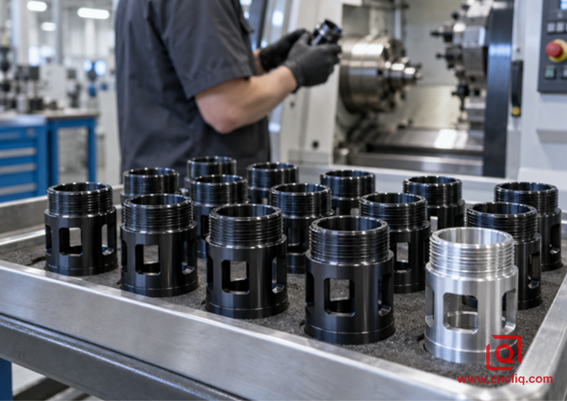
Representative repeat-production sensor sleeves with threaded noses and radial windows.
What to Send for a Fast, Accurate RFQ
Send a 3D model plus a controlled 2D drawing. Identify aluminum alloy and temper, raw-stock preference if important, thread standard and designation, class of fit, hand, number of starts, full-thread engagement, runout or relief, datum relationship, surface finish, and sealing requirement. Mark whether dimensions apply before or after anodizing.
Also include annual demand, batch size, prototype quantity, mating fastener material, controlled assembly torque or load, expected assembly cycles, cleanliness requirement, inspection documents, packaging, and delivery location. If you are undecided between form and cut threading, say so. A capable supplier can evaluate the geometry and quote the safest process instead of silently choosing the cheapest-looking toolpath.
Need an engineering review? Send your STEP file and drawing through the Liqin contact page. We can compare single-point cutting, cut tapping, form tapping, thread rolling, and turn-mill routing against the same drawing. The result should be a thread that gauges, assembles, and stays reliable—not merely one that looks sharp in a photograph.
FAQs
1. Are formed threads always stronger than cut threads in aluminum?
No. Forming preserves material flow around the flank and adds local cold work, which can improve stripping or fatigue performance in a suitable ductile alloy. The real result still depends on pilot diameter, percentage of thread, alloy and temper, wall support, lubrication, engagement, mating fastener, and load direction. A poorly formed thread can fail earlier than a correctly cut one, so the choice must be validated on the actual part.
2. Can a form tap use the same drill size as a cut tap?
No. A form tap needs a larger pre-hole because it displaces material into the profile instead of removing it. For an M6 × 1.0 teaching example, general formulas place a cut-tap hole near 5.0 mm and a form-tap hole near 5.5 mm, but production must follow the selected tool maker’s chart and required class. Substituting one drill can cause incomplete crests or excessive torque.
3. Which method is better for a blind aluminum hole?
Form tapping is attractive because it creates no thread chips, but only when the alloy is formable, the wall can withstand pressure, the pre-hole is stable, and lubrication is reliable. A spiral-flute cut tap is often better for lower volume, uncertain material, or geometry that cannot tolerate forming load. Blind-hole depth must include tool lead, bottom clearance, and drill point—not just usable thread.
4. Should an anodized aluminum thread be gauged before or after finishing?
The drawing and quality plan should state the acceptance condition. Critical threads may need checks before and after anodizing, especially when masking or pre-finish compensation is used. Anodizing can alter fit at flanks, crests, and edges, so machining, finishing, and customer teams should agree on coating type, thickness, masking, gauge class, and any permitted post-finish operation.
5. What is the best method for an external thread on a CNC lathe?
Single-point cutting is usually the most flexible choice for prototypes, large diameters, special profiles, and threads tied to a shoulder or seal land. External rolling can be faster and chipless in repeat production when material, blank diameter, wall support, access, and equipment suit the job. A self-opening die head may also compete. The best route follows volume, geometry, tolerance, and downstream finish.
Summary
Form threading displaces ductile aluminum to create a chipless, locally cold-worked profile, while cut threading removes material and offers broader flexibility for prototypes, special geometries, thin walls, and varied alloys. On a CNC lathe, the winning process protects the datum relationship, controls pre-thread diameter, manages torque or chips, accounts for anodizing, and proves function with agreed gauges. Share the complete drawing, alloy, engagement, finish, inspection condition, and volume early so the supplier can select a stable method and quote without hidden risk.
Contact Information
Company: Ningbo Liqin Industry Co., Ltd.
Daily customer maintenance & after-sales support:service@shturl. zhuwanying@cncliq.com
New inquiry, quotation & order discussion:business@shturl. zhouli@chinaliqin.com
Hotline: +86 18757148656
Disclaimer
All technical articles, material specifications, machining recommendations, and surface treatment details published on this blog are for informational and reference purposes only. Please note that general blog insights do not replace signed technical agreements. Because custom parts vary by material heat numbers, machine calibrations, and specific tolerances, binding quality specs are governed solely by your approved CAD drawings, signed contracts, and formal quality plans.
All customer case studies featured on this blog have been thoroughly anonymized and sanitized. The performance metrics, manufacturing workflows, and imagery displayed serve solely to demonstrate our custom machining capabilities and do not represent a single universal standard for all orders.
Liqin Manufacturing Team
Built on 18 years of precision engineering experience, Ningbo Liqin Industry manufactures high-tolerance metal components for demanding global markets. We operate out of a 6,500 m² production hub equipped with over 150 machines, running 4-axis and 5-axis CNC machining, mill-turn machining, cold extrusion, and pressure die casting under one roof. This setup allows us to manage projects seamlessly, taking parts from initial CAD concepts directly to finalized shipments.
We handle quality control with zero compromise. We treat tight tolerances with the engineering discipline they require. Backed by ISO 9001, ISO 13485, and IATF 16949 certifications, our QA engineers run strict IPQC, FQC, and OQC checks on every single production batch. From CMM dimensional mapping and optical profiling to hardness and salt-spray testing, we validate your critical specs upfront—so you receive drop-in ready components with zero assembly headaches or costly line stoppages. On top of manufacturing, you can rely on us for two-hour response times on new RFQs, direct support for prototype sampling, and smooth export shipping across Europe, North America, Asia, and Oceania.
Welcome your inquiries and samples. Visit our website or contact us directly for a competitive quote!
