 English




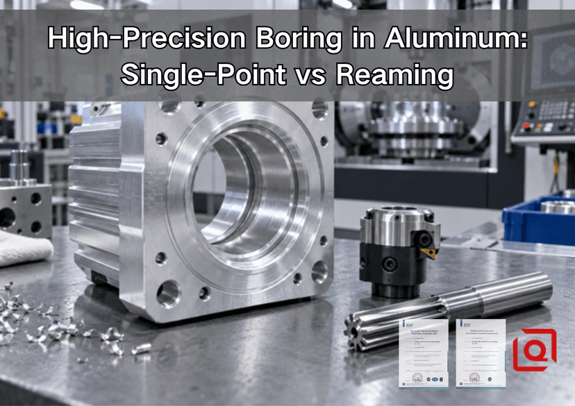
Are you still deciding whether a tight aluminum bore should be single-point bored or reamed? A prototype may look fine. Then the production lot reaches the gauge: size drifts, a spiral mark appears, or the bore no longer lines up after unclamping. Below is the shop-floor version of that choice - what each tool can control, the failure signs we watch for, and the drawing details needed for a defensible quote.
Here is the quick answer. We normally lean toward single-point boring for location, form, adjustment, or an odd diameter. With a sound pre-hole and many repeated parts, reaming often makes better production sense. Some prints call for both tools: drill or interpolate first, touch the axis with a semi-bore, and let the reamer take the last controlled cut. Which route survives production comes down to the print, the actual alloy, L:D, order quantity, and how the bore will be verified.
Fast selection rule: A reamer follows the hole it receives. A boring tool can deliberately correct that hole. If the pre-hole axis is wrong, a reamer may improve diameter and finish without fully repairing true position or straightness.
Single-Point Boring vs Reaming at a Glance
|
Decision factor |
Single-point boring |
Reaming |
|
Cutting action |
1 adjustable cutting edge enlarges an existing hole |
Multiple cutting edges remove a small, controlled allowance |
|
Best reason to choose it |
Correct axis, roundness, taper, or a special diameter |
Repeat a standard final size quickly across a batch |
|
Pre-hole dependency |
Can correct moderate pre-hole error when rigidity and stock allow |
Strongly dependent on pre-hole size, straightness, alignment, and allowance |
|
Diameter flexibility |
High; offsets or an adjustable head change finished size |
Low; the tool is closely tied to its nominal diameter |
|
Cycle time |
Usually longer because setup and offset control are more involved |
Usually shorter after the process is proven |
|
Typical production fit |
Prototype, mixed sizes, large bores, stepped bores, strict geometric control |
Medium- or high-volume identical holes with stable incoming geometry |
|
Main aluminum risk |
Bar deflection, chatter, built-up edge, thermal size drift |
Material pickup, oversize cutting, chip packing, bell-mouth, inherited mislocation |
|
Tooling economics |
More setup skill, but 1 tool can cover a diameter range |
Dedicated tool cost, but low cycle time can reduce cost per hole |
What High Precision Must Mean on the Drawing
A diameter tolerance alone is not a complete bore requirement. We have seen bores pass a 2-point size check and still bind during assembly. Taper, lobing, tilt, mislocation, or a rough bearing track can hide behind a good-looking diameter. So, before choosing a tool, split the requirement into 5 separate questions: size? roundness? cylindricity? axis location or true position? surface texture? If a face, another diameter, or a rotating feature establishes function, the print may also need perpendicularity, runout, or an appropriate location control.
ISO 286-1 is where the familiar code system for linear-size tolerances and fits comes from. An H7 callout is not 1 universal number; its tolerance width changes with nominal diameter. For example, published ISO 286 tables place an H7 hole above 30 mm and through 50 mm at 0 mm lower deviation and +0.025 mm upper deviation. That controls size, not automatically roundness or true position. ASME Y14.5 supplies the shared GD&T language for stating the geometric relationships that size alone leaves open.
Start at the assembly bench, not at the tool cabinet. What does the hole do: carry a bearing, guide a valve, locate a dowel, seal fluid, align optics, or simply clear a bolt? A bearing housing may care about axis alignment and cylindricity. A dowel hole may prioritize true position. A hydraulic spool bore may combine size, straightness, surface texture, and leakage risk. The manufacturing method should follow function, not habit.
Why Aluminum Changes the Hole-Finishing Decision
Aluminum is easy to remove but not automatically easy to hold at micron-level consistency. Many wrought grades cut at high speed, yet a dull or poorly lubricated edge can smear material onto the tool. This built-up edge changes the effective cutting geometry, then marks the bore or shifts its size. Our practical guide to machining 6061 aluminum goes deeper into that problem. In day-to-day cutting, a keen edge, a chip with enough body, and a clear exit path matter more than a fashionable rpm figure.
Temperature can move the reading surprisingly fast. If a warm part is measured immediately and the bore is corrected to nominal, it can settle smaller after temperature equalization. Thin housings add elastic distortion: clamp pressure can make a bore look round in the fixture and out-of-round after release. Cast aluminum brings another variable. A silicon-rich casting adds abrasion to the picture; tooling that behaves well in 6061-T6 or 7075-T651 billet may wear quite differently there.
That is why no responsible supplier should promise a universal feed, speed, stock allowance, or achievable tolerance from alloy name alone. Cutter grade, edge preparation, runout, coolant, hole depth, interrupted features, machine stiffness, fixture load, and actual material heat all influence the result. Toolmaker data is the starting point; first-article evidence is the decision point.
How Single-Point Boring Works in Real Production
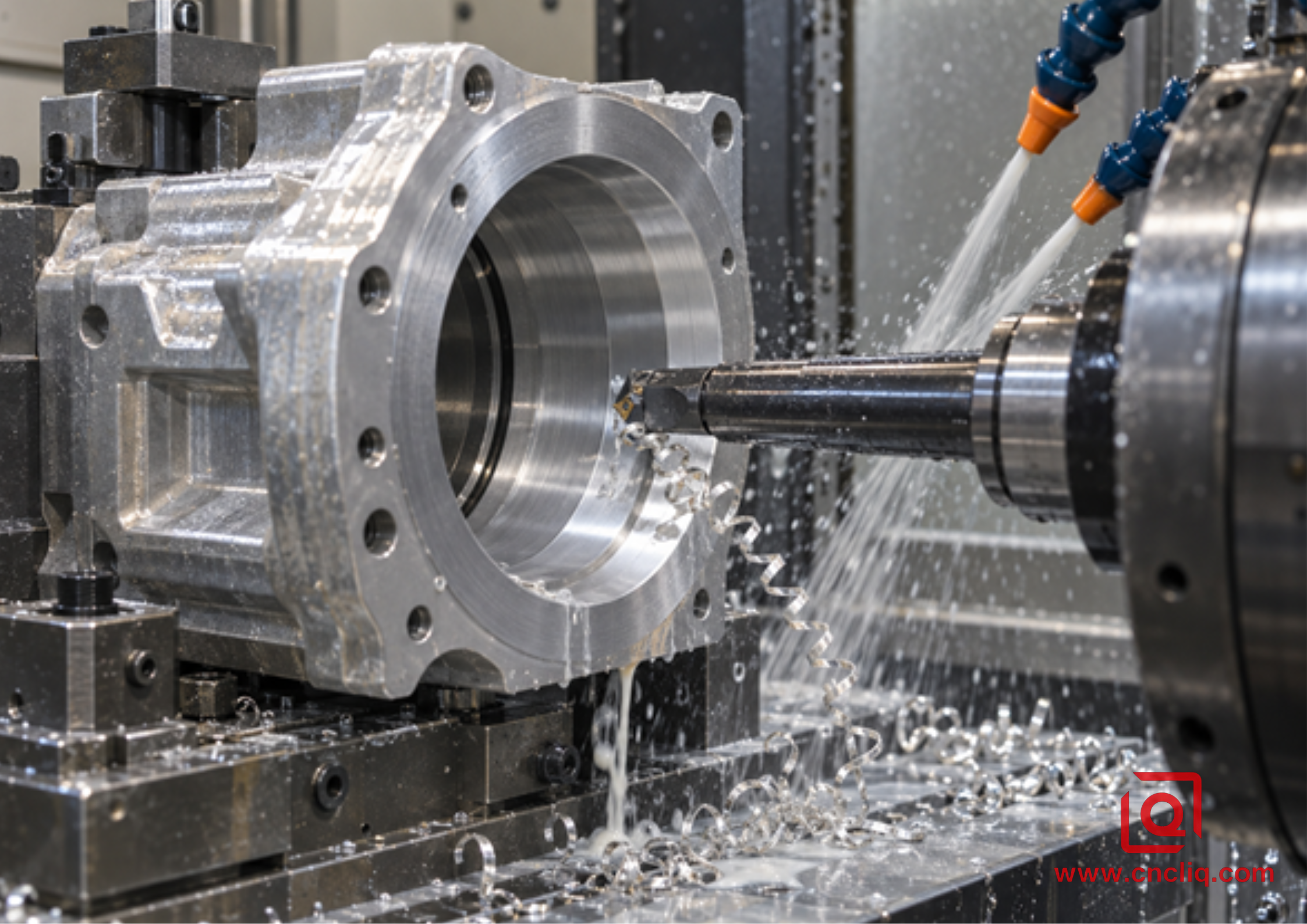
Single-point boring can establish a controlled bore axis and allows measured diameter correction through tool offsets.
A single-point boring tool removes material with 1 cutting edge. In a machining center, the head or bar spins and the clamped component stays put. At the lathe, that motion is usually reversed: the workpiece turns around the bar. Either arrangement gives the machinist something valuable. The cutting path can establish a new finished circle instead of obediently tracing every error left by the drill.
Where boring is strongest
We reach for boring on odd diameters, larger holes, steps, back-bored features, and short runs where a dedicated reamer would spend more time in purchasing than in the spindle. It is also valuable when the bore axis must relate closely to machined datums in the same setup. For complex housings, our article on multi-axis CNC milling of aluminum geometries shows why reducing re-clamping helps protect feature relationships.
Where boring fails
The boring bar is a cantilever. More overhang means less stiffness, and a small bar deep in a bore is vulnerable to deflection and chatter. The symptoms are familiar: a repeating wave pattern, a bell-mouth at entry, taper through depth, noisy cutting, or unstable size. The safest first move is usually mechanicaluse the largest bar that clears the hole and chips, shorten overhang, improve holder contact, and strengthen the fixturebefore making random speed changes.
How Reaming Works in Real Production
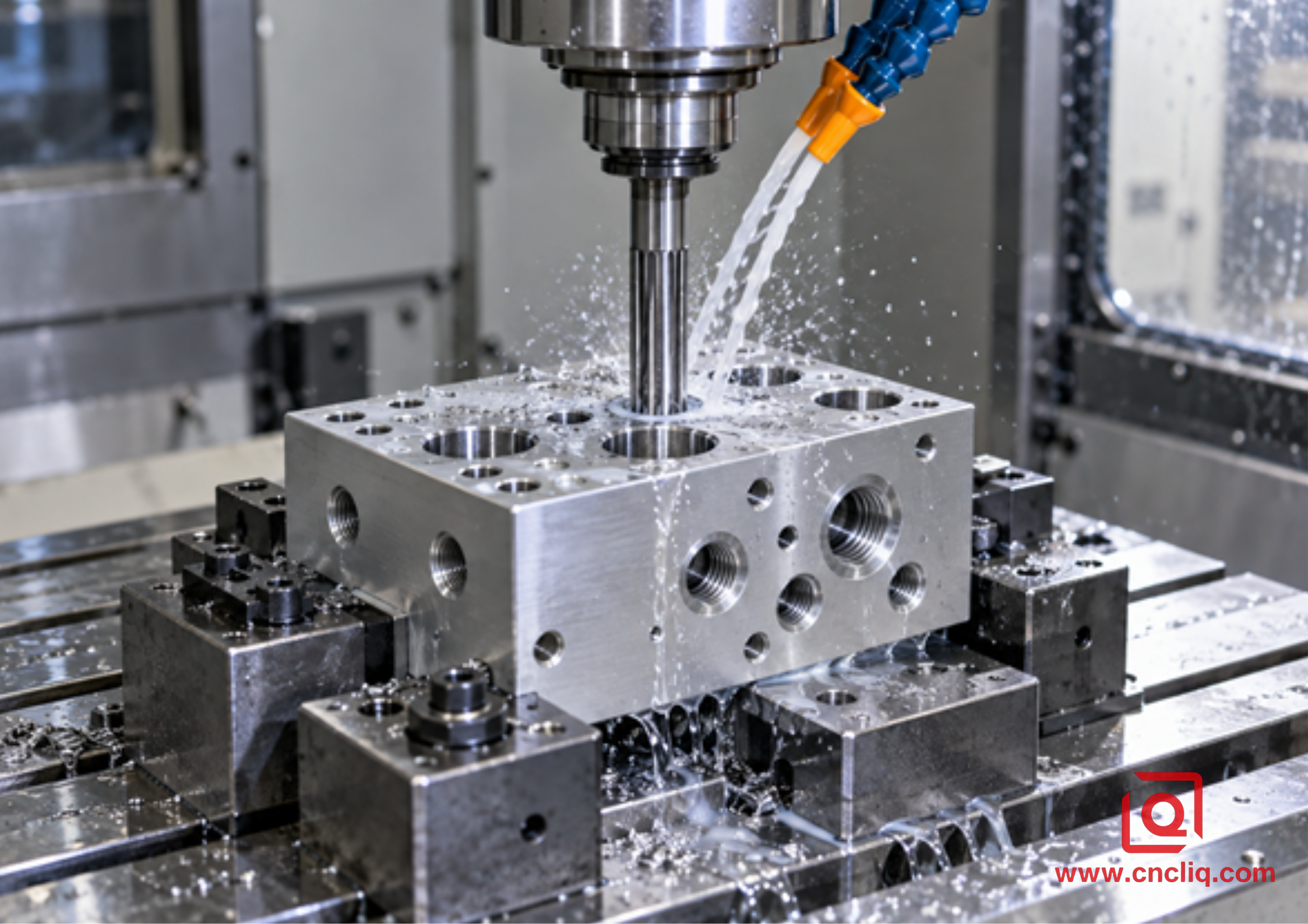
Reaming is efficient when the pre-hole has uniform allowance, sound alignment, and enough flute space for aluminum chips.
A machine reamer uses multiple cutting edges to remove a small allowance from an existing hole. It is a finishing tool, not a substitute for producing a sound pre-hole. Once pre-hole geometry, holder runout, coolant, and tool condition are controlled, reaming can deliver fast, repeatable diameter and finish across many identical parts.
Kennametals reaming guide emphasizes 3 practical points: leave enough material for the reamer to cut instead of rub, keep the setup rigid with limited overhang, and do not peck a reamer like a drill. Its general guidance also notes that reaming feeds are often higher than drilling feeds while cutting speed is lower, but the exact starting data must come from the tool manufacturer for the selected tool and alloy.
Where reaming is strongest
Reaming performs well on small and medium standard diameters, especially when the same hole repeats across a production batch. Multiple cutting edges share the work, and a proven tool can move directly through the hole in 1 continuous pass. The resulting cycle is easy to automate and easier to time in a quotation than repeated measuring and offset adjustment.
Match the tool to the hole. Spiral direction, flute space, through-tool coolant, and edge material all change chip behavior. For a sourced production example, Seco's aluminum case study documents H7 finishing with a 26 mm PCD reamer.
Where reaming fails
A reamer tends to follow the established path. A drilled or interpolated hole can be off location, bowed, or tapered; after reaming, the diameter may read nicely while the axis is still wrong. Leave almost nothing and the margins rub. Leave too much and torque climbs, flutes fill, and the finished hole may grow. Excessive runout makes 1 flute work harder than the others. Reversing the reamer in the bore can drag edges across the new surface. Interrupted cross-holes may shock the cutting edges and produce local marks unless the tool and process are designed for them.
Decision Matrix: Which Process Fits Your Aluminum Part?
|
Part condition |
Preferred route |
Reason |
|
Prototype with a special bore size |
Single-point bore |
Adjustable diameter avoids a dedicated reamer and supports quick engineering changes |
|
Large bearing bore tied closely to a machined face |
Single-point bore in the same setup |
Better opportunity to establish axis and geometric relationship to the datum |
|
1,000 identical H7-size holes with stable pre-holes |
Ream after process validation |
Short cycle and predictable repeatability can lower cost per part |
|
Small, deep blind hole in gummy wrought aluminum |
Ream only with suitable spiral, coolant, and chip path; otherwise review |
Chip packing, runout, and heat can dominate the result |
|
Pre-hole has location or straightness error |
Semi-bore, then ream if finish and volume justify it |
Boring establishes the axis; reaming provides efficient final sizing |
|
Stepped, tapered, or interrupted internal geometry |
Usually single-point bore or engineered special tool |
A standard reamer is not inherently flexible across changing geometry |
|
Thin-walled housing distorted by clamping |
Fix workholding first, then select the finishing tool |
Neither process can guarantee free-state geometry if the part is machined while distorted |
The Hybrid Route: Bore First, Ream Last
Boring vs reaming is not always an either-or choice. A hybrid route is often the most robust for a production bore that must combine axis control with fast final sizing:
1. Create the pilot hole by drilling or circular interpolation.
2. Semi-bore enough depth to establish the intended centerline and remove major taper or lobing.
3. Leave a uniform final allowance recommended for the actual reamer, diameter, and material.
4. Ream in 1 continuous, well-lubricated pass with controlled runout and chip flow.
5. Measure size and geometry after the part has been released and temperature has stabilized.
This route adds a tool and a step, so it is not automatically cheaper. It earns its place when reaming alone inherits too much pre-hole error, while boring every production part to final size consumes too much cycle time or operator adjustment. For deep passages, review the related aluminum deep-hole machining guide before locking the drawing.
Anonymous Customer Case: Servo Motor Front Cover
An automation-equipment customer requested an aluminum servo motor front cover with a central bearing seat, a locating spigot, and a bolt pattern related to the mounting face. The application was intentionally anonymized, and the figures below illustrate a plausible process-development case rather than a universal capability claim. The geometry is closely related to Liqin's published servo motor front-cover product, which uses ADC12 aluminum and CNC finishing of internal and external circular features.
Initial problem
The first process drilled and reamed the bearing seat after a separate face-milling setup. Diameter results were repeatable near the upper half of the tolerance band, but CMM inspection showed the bore axis was not consistently square to the mounting face after unclamping. Changing reamer size could not correct the datum relationship. The team also found that clamp pressure near the thin flange influenced free-state roundness.
Revised process
The datum face and bore were brought into 1 machining setup. Soft-jaw contact was moved toward stiffer ribs, clamp load was reduced to the minimum proven by cutting trials, and the pre-hole was interpolated undersize. A short, rigid single-point boring tool then established the bearing-bore axis. For the planned batch, the final choice depended on volume: final boring supported early prototypes and diameter changes; after the design froze, a dedicated reamer was trialed as the finishing step to reduce cycle time. Released-part inspectionnot in-fixture measurementwas used for approval.
Outcome and lesson
The decisive improvement did not come from declaring 1 tool more accurate. It came from aligning the process with the functional requirement: datum strategy and workholding controlled the axis; boring corrected the path; reaming was considered only after the incoming geometry became stable. This is the same logic buyers should apply to motor housings, pump covers, bearing carriers, and the precision bores found in a custom aluminum manifold block.
Inspection: Prove More Than Diameter
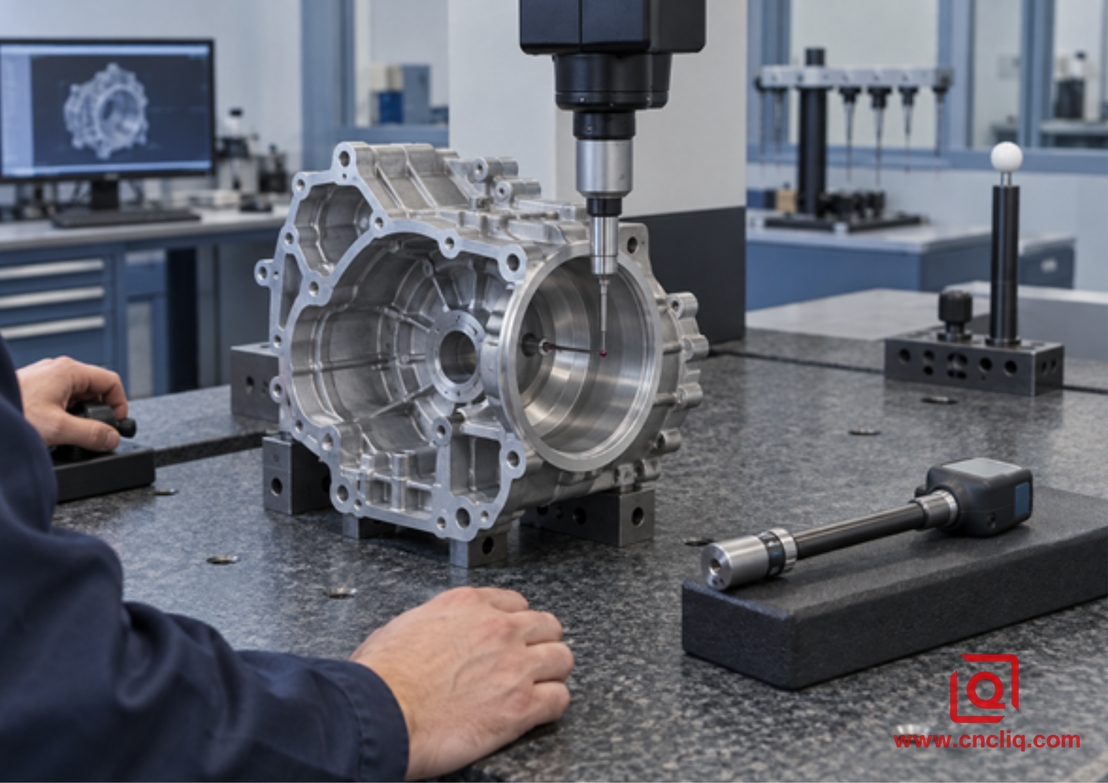
A capable inspection plan separates size from roundness, cylindricity, and datum-related location.
A production inspection plan should match the risk. A calibrated bore gauge is efficient for comparative size checks after it is mastered to an appropriate standard. Air gauging can provide sensitive comparative results for high-volume cylindrical features. A CMM helps evaluate axis location, orientation, and relationships to datums, while a roundness or form instrument is the stronger choice when the drawing demands detailed circularity or cylindricity evaluation. A surface-roughness instrument is required when Ra or another texture parameter is specified; appearance alone is not evidence.
Do not combine all of those into 1 vague 0.01 mm precision statement. Define the characteristic, measurement method, sampling frequency, temperature condition, and acceptance rule. Liqin's article on CMM inspection for custom aluminum machining provides more context on datum-based verification and thermal control.
An effective quality plan connects every critical drawing requirement to a defined inspection method, acceptance limit, and recorded result. This traceable approach reduces ambiguity between the buyer, machinist, and quality engineer while supporting faster root-cause analysis if a dimension begins to drift. For production orders, the control plan should also identify first-article checks, in-process sampling, final inspection, gauge calibration status, and the reaction plan for any nonconforming result. Clear records do more than prove compliance: they protect assembly performance, shorten approval cycles, and give purchasing teams greater confidence when they scale a validated prototype into repeat production.
|
Characteristic |
Useful inspection method |
Common mistake |
|
Bore size |
Mastered bore gauge, air gauge, or suitable internal micrometer |
Relying on a caliper for a tight functional bore |
|
True position or perpendicularity |
CMM or dedicated functional gauge designed to the drawing |
Assuming a correct diameter proves a correct axis |
|
Roundness or cylindricity |
Form-measuring instrument or validated multi-section method |
Checking only 1 section at 2 points |
|
Surface texture |
Calibrated roughness tester with defined cutoff and direction |
Judging a shiny surface by eye |
|
Batch stability |
First-off approval plus in-process SPC on the critical feature |
Inspecting only the final packed lot |
DFM and RFQ Checklist for a Quote That Means Something
A machining supplier cannot choose responsibly from a screenshot or nominal diameter alone. Send the native 3D model and a controlled 2D drawing, then identify the bores function. Before a useful quote can be built, the RFQ needs a few specifics:
· Name the alloy and condition: 6061-T6, 7075-T651, or the actual casting grade, not simply aluminum.
· State nominal size and both limits. Mark clearly whether they apply on bare metal, after coating, or at both stages.
· Show the full bore: depth, blind or through, entry chamfer, bottom clearance, grooves, plus any cross-hole that breaks the cut.
· Build a usable datum reference frame and attach the position, orientation, runout, roundness, or cylindricity controls that function actually needs.
· Call out surface texture where it matters, and tell us why: bearing fit, seal track, sliding valve, or optical alignment all drive different decisions.
· Prototype and annual quantities, expected batch size, target lead time, and whether tooling cost may be amortized.
· List the records your approval process expectsperhaps an FAI, CMM report, material certificate, capability study, or PPAP package.
· Do not leave the finishing details to assumption. Define cleaning, deburring, anodizing, masking, and pack-out.
Surface treatment deserves explicit attention. Anodizing changes the surface and can affect a tight bore, so the drawing should state masking, post-process size, and inspection stage. The broader aluminum CNC milling and tolerance guide explains why blanket tight tolerances increase cost without improving function.
Need a process recommendation, not just a unit price? Send Liqin your STEP file, 2D drawing, alloy, quantity, and critical bore callouts. Our engineering team can review whether final boring, reaming, or a hybrid sequence best protects assembly risk. Request a DFM review and quotation.
When the Gauge Says No: A Shop-Floor Troubleshooting Table
|
Symptom |
Likely area to investigate |
First checks |
|
Bored hole tapers through depth |
Bar deflection, insert wear, thermal drift, weak workholding |
Reduce overhang, increase bar diameter, inspect edge, check part temperature and released condition |
|
Reamed hole is oversize |
Holder runout, built-up edge, misalignment, excessive speed, damaged chamfer |
Indicate the tool, inspect margins, verify holder and coolant, review pre-hole |
|
Finish shows chatter rings |
Low rigidity, incorrect engagement, poor tool condition, unstable feed or speed |
Fix mechanical stiffness first; then use toolmaker parameter guidance |
|
Diameter passes but assembly binds |
Roundness, taper, position, coating buildup, burr at cross-hole |
Measure geometry and coating state, not only 2-point size |
|
First parts pass and later parts drift |
Tool wear, aluminum pickup, coolant temperature, gauge method |
Track size by part sequence, clean and inspect the edge, validate measurement repeatability |
Click Here For Your Inquiry 👆
FAQ
1. Is boring always more accurate than reaming in aluminum?
No. The 2 tools solve different problems. A boring head lets the operator correct an axis and nudge size; a proven reamer can run the same sound pre-hole quickly, part after part. First decide what accurate refers to. Size is not position, position is not roundness, and none of them is protected if the machine, holder, fixture, temperature, or gauge is unstable.
2. My drilled hole is off center. Will a reamer pull it back?
Only to a limited and unpredictable extent. A reamer generally follows the path and geometry presented by the pre-hole. If true position or straightness is critical, use interpolation or semi-boring to establish the axis before reaming, and verify the finished relationship to the drawing datums.
3. How much stock should be left before reaming aluminum?
There is no safe universal allowance. It changes with finished diameter, reamer design, tool material, alloy, depth, coolant, and pre-hole quality. Too little can make the tool rub; too much can overload the edges and pack chips. Use the selected reamer manufacturers data, then confirm with a controlled first-article trial.
4. Which process is cheaper for custom aluminum parts?
On prototypes and changing designs, boring usually avoids ordering a fresh reamer every time the diameter moves. Once the design and pre-hole have settled, the arithmetic can flip. Reaming may shorten each cycle enough to win on a medium or long run. Compare the whole job: tool purchase, setup, gauge time, expected tool life, scrap exposure, and what a failed assembly costs. Spindle minutes tell only part of the story.
5. What should I send for a reliable boring or reaming quotation?
Send the 3D model, controlled 2D drawing, aluminum grade and temper, bore limits, GD&T datums, surface texture, depth and interruptions, coating state, quantities, inspection documentation, and assembly function. For sensitive designs, put the NDA in place first; then transfer the complete data set through the agreed channel.
Summary
There is no universal winner. Boring earns its keep when size must be adjustable, the axis needs correction, geometry is unusual, or the design is still moving. Reaming earns its place after the pre-hole is stable and repeated cycle time starts to matter. On the difficult jobs, we may use both. Hold the component without squeezing it, let temperature settle, and check size, form, location, and texture against the drawing, not against a good-looking surface. Send the functional callouts with your RFQ so the process is engineered around assembly risk rather than guesswork.
Contact Information
Company: Ningbo Liqin Industry Co., Ltd.
Daily customer maintenance & after-sales support:service@shturl. zhuwanying@cncliq.com
New inquiry, quotation & order discussion:business@shturl. zhouli@chinaliqin.com
Hotline: +86 18757148656
Disclaimer
All technical articles, material specifications, machining recommendations, and surface treatment details published on this blog are for informational and reference purposes only. Please note that general blog insights do not replace signed technical agreements. Because custom parts vary by material heat numbers, machine calibrations, and specific tolerances, binding quality specs are governed solely by your approved CAD drawings, signed contracts, and formal quality plans.
All customer case studies featured on this blog have been thoroughly anonymized and sanitized. The performance metrics, manufacturing workflows, and imagery displayed serve solely to demonstrate our custom machining capabilities and do not represent a single universal standard for all orders.
Liqin Manufacturing Team
Built on 18 years of precision engineering experience, Ningbo Liqin Industry manufactures high-tolerance metal components for demanding global markets. We operate out of a 6,500 m production hub equipped with over 150 machines, running 4-axis and 5-axis CNC machining, mill-turn machining, cold extrusion, and pressure die casting under one roof. This setup allows us to manage projects seamlessly, taking parts from initial CAD concepts directly to finalized shipments.
We handle quality control with zero compromise. We treat tight tolerances with the engineering discipline they require. Backed by ISO 9001, ISO 13485, and IATF 16949 certifications, our QA engineers run strict IPQC, FQC, and OQC checks on every single production batch. From CMM dimensional mapping and optical profiling to hardness and salt-spray testing, we validate your critical specs upfrontso you receive drop-in ready components with zero assembly headaches or costly line stoppages. On top of manufacturing, you can rely on us for two-hour response times on new RFQs, direct support for prototype sampling, and smooth export shipping across Europe, North America, Asia, and Oceania.
Welcome your inquiries and samples. Visit our website or contact us directly for a competitive quote!
