 English





Have you ever seen a thin aluminum tube run true in OP10, then wobble after the back end was picked up? I have. The first diameter looks right. The bore looks right. After the flip, rear face complete, the assembly gauge tells us the two axes have parted company. Annoying? Certainly. A mystery? Usually not.
This guide follows that problem from the print to the finished tube. First RFQ note in my margin: dual-spindle machine available, yes; transfer plan not yet answered. I ask for an OP10 and OP20 split. Next three notes: grip surface, surviving datum, released-part check. With those blanks filled in, the machine choice starts to mean something.
Quick shop answer: the main spindle does the front work and establishes the important axis. The right-hand spindle comes alongside, receives the tube, then exposes the end we could not reach before. Ports at 90 degrees? One flat? A cable window? Put each feature on the operation sheet and match it to an axial or radial driven station. Fewer handoffs help. They do not cancel jaw distortion, heat, chips, or a weak drawing.
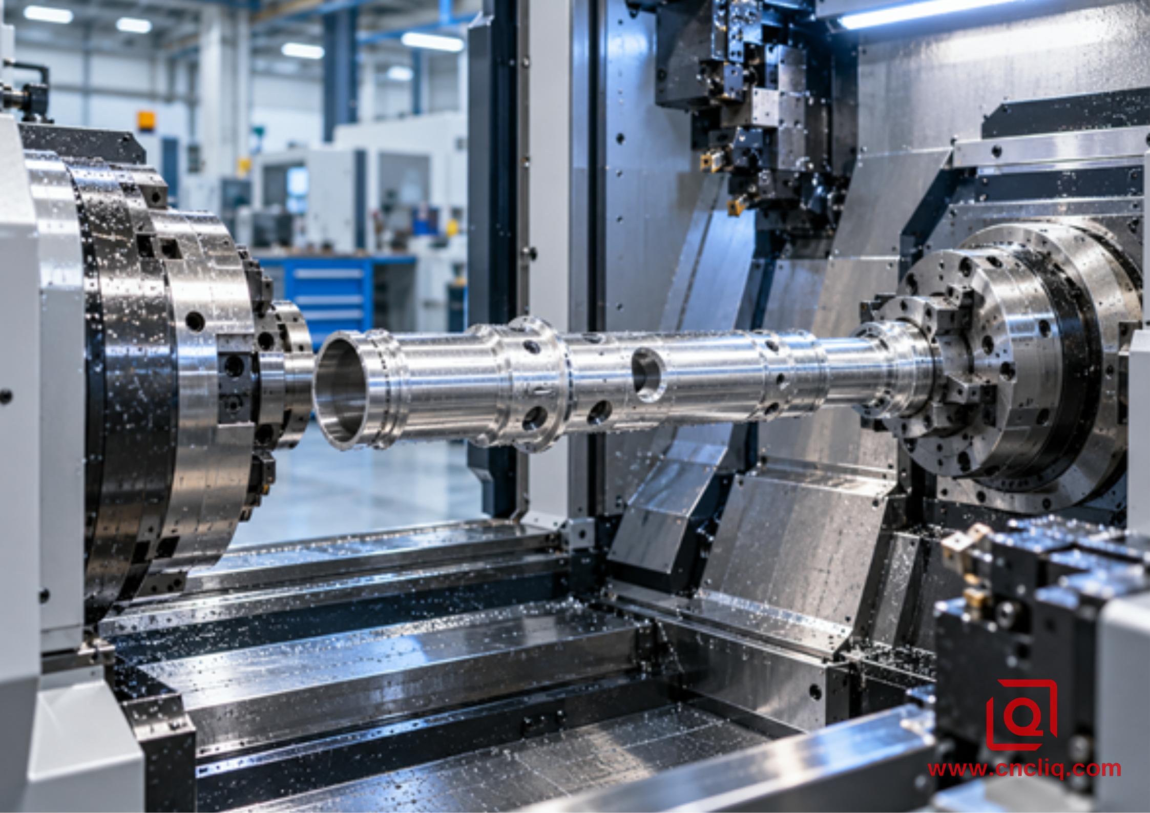
Synchronized dual-spindle turning of a complex aluminum tube
1. What “Synchronized” Means at the Chuck
Machine sketch in the setup book: left chuck = main; right chuck = sub; the transfer takes place in the gap. The receiving chuck approaches while the tube is turning. No stop-and-grab shortcut. On the control page I want rpm agreement and the required phase before any jaw moves. Then Z advances to the stop. Jaws close. Clamp input changes state. We pause there during prove-out. Only then may cutoff or release happen.
Reference on the setup review: Haas Lathe Operator’s Manual, 2021, section on Synchronous Spindle Control. That manual shows the practical idea well. The pair speeds up together, runs together, and slows together; it can support both ends or make a rotating pass-off. I would never copy its codes to another control without that builder’s book open. Codes, speed limits, orientation logic, and clamp confirmation must follow the actual builder’s manual.
What do I want to see during prove-out? Not a marketing video. I want a slow cycle with the real jaws, real blade, real stick-out, and real stock. Is there daylight between the tube and the stop? Does the part pull in Z when the second chuck closes? Does a ribbon chip follow the transfer land into one jaw? Small clues, but they decide the result.
Two chucks alone are not synchronization. A good handoff is a timed handshake: speed, phase, Z position, seating, clamp signal, separation, clearance. Our guide to live tooling on CNC lathes covers the other half of the process. Synchronization moves and supports the tube; live tools make the cross-holes, flats, face holes, slots, and off-axis threads.
2. Why an Aluminum Tube Fights Back
CAD review, 09:00. The tube looks stiff on screen. Shop trial, 11:20. Shop answer: no. Five items go on my thin-wall check sheet: jaw load, boring load, interruptions, stock stress, temperature. Each influence may be small. Put three together and the bore can miss the assembly condition.
Three-jaw distortion is the first check. Close narrow jaws too firmly and a round bore may become slightly three-lobed while clamped. The tool cuts a round path inside that constrained shape. Open the chuck and the wall springs toward its free state. One micrometer reading at one clock position can miss the pattern.
Then comes cutting force. A long boring bar pushes sideways. Under the bar, the wall gives. Behind the edge, it comes back. When the cross-drill breaks through, I cannot judge the inside edge from the window; the borescope has to do that job. One long silver ribbon around the seal land is enough to turn a good finish into a reject. None of this is unusual.
Heat deserves numbers. Material note for 6061: published room-temperature expansion data are close to 23 micrometres per metre for each degree Celsius. Worked example in the margin: diameter 100 mm; assumed uniform temperature shift 10 degrees Celsius. Arithmetic: 23 x 10^-6 x 100 x 10 = 0.023 mm. I do not enter 0.023 as an offset. The tube is not uniformly hot; the number only tells us the size of the trap. It does explain why a warm reading beside the machine can disagree with a stabilized reading in inspection.
A short risk list for the print review:
· Does the wall become thin beneath a window, port, or groove?
· Can both jaws grip a stiff land instead of a seal surface?
· Is the critical bore finished before or after disruptive side milling?
· Where can chips hide during handoff?
· Which dimensions cross from main-spindle work to sub-spindle work?
· Is final acceptance based on the released part?
For more detail on temperature and lobing, use our guide to tight diameter tolerances in aluminum turning.
3. A Nine-Step Handoff We Can Audit
Setup sheet, first article. I want the transfer written as individual events, not buried inside one line called “sub-spindle operation.”
1. Grip the raw tube, bar, extrusion, or near-net blank on a known contact length.
2. Rough the bore and OD with enough balance that one wall is not left carrying all released stress.
3. Machine front-side details that must stay tied to the main datum.
4. Clear the transfer land and the secondary jaws. A chip behind jaw 2 is enough to spoil the handoff.
5. Bring both spindles into the approved synchronized state.
6. Feed the sub-spindle to its stop and clamp at the proved pressure.
7. Confirm clamp state, then cut off or release the main chuck.
8. Retract along a checked clearance path and finish the back face, thread, bore, groove, or driven-tool feature.
9. Catch or unload the tube without dropping a seal land onto the chute.
One real-looking check helps. Trial 1: clean land, clamp input on, then 0.04 mm of Z pull as the receiving jaws close. Do not hide that movement with an offset. Check stop contact, jaw lead-in, phase, and pressure first. An offset can make final length pass while the grip problem remains.
Collision simulation belongs here too. Include jaw steps, chuck bodies, holder blocks, cutoff blade, unfinished stock, and full tool projection. The finished CAD model is only one item in the enclosure.
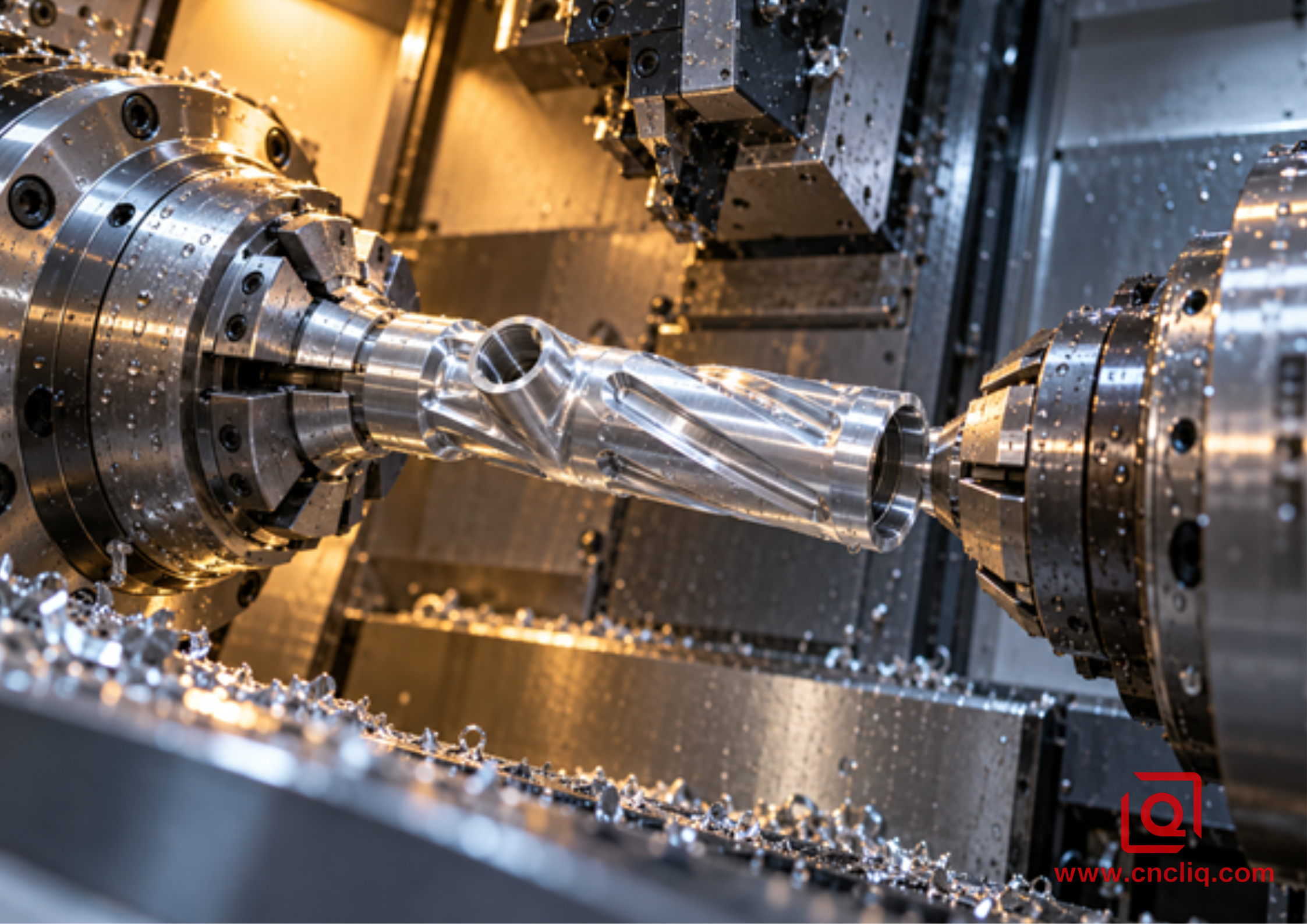
Close-up of a synchronized spindle handoff
4. Workholding: Pressure Is Only Half the Answer
Shop note, Monday, 08:20. Tube OD 48.00 mm, wall 1.8 mm, grip length 22 mm. Bore checked 42.012 mm while clamped. After release: 42.027 at 12 o’clock, 42.009 at 3 o’clock. We did not touch the offset. We reduced chuck pressure within the approved range and increased contact with corrected bored jaws. The next released readings grouped within 0.003 mm. The insert had not caused the first error. The grip had.
That example is illustrative, not a Liqin production record, but the diagnostic order is sound. Measure the free part before chasing compensation.
Workholding shortlist on the bench: bored jaws, split collet, expanding mandrel, fitted sleeve. Four contact patterns, four different ways to load the wall. There is no tick-box winner. The print cannot answer alone. Review wall thickness, grip length, alloy temper, stock spread, unsupported length, interrupted features, torque, and the operation that follows. A broad jaw can still distort a weak section. I have seen the mandrel cure OD lobing and create a bell at the ID instead.
“Use X bar” without chuck, jaw, diameter, and rpm is a number with its context cut off. My setup line keeps all five fields together: chuck model; jaw profile; grip diameter; rpm; expected cut. Begin inside the machine and workholding maker’s limits. Prove the lowest stable setting, then record the complete setup.
Main and sub jaws often need different designs. The main spindle may carry roughing torque. The secondary spindle may touch a finished thin land and perform a light face plus thread. Copying the same jaw concept to both sides is convenient, not necessarily correct.
Inspection after release should cover several clock positions and axial sections. For a critical bore, agree whether size, roundness, runout, air gauging, or CMM geometry proves function. “Checked with micrometer” is not enough when lobing is the risk.
5. Tool and Cut Order: A Practical Review
Tool crib question: is the insert made for aluminum, and is the edge still keen? Aluminum commonly rewards a polished, positive geometry with room for the chip to leave. A steel-oriented honed edge may rub, collect built-up edge, and smear the surface. Start with the selected toolmaker’s grade and geometry data. Prove the cutting window on the actual alloy, temper, diameter, wall, and setup.
Roughing and finishing are different jobs. Roughing removes stock and reveals movement. Finishing establishes size and surface with a controlled allowance and a known edge. A large nose radius is not automatically better on a flexible wall. If radial force rises, the finish may look smooth while size drifts.
Order matters. On a ported tube I normally want heavy or disruptive work before the last critical bore and seal-land passes, provided tool access permits it. Why? Cross-drilling and window milling can relax the wall. Finish too early and the feature that looked perfect moves later.
Parting has its own failure list: blade not square, excessive projection, weak coolant delivery, recut chip, or a remaining core that pulls the tube. The aluminum grooving and parting guide explains that operation in depth. When the tube becomes very small and slender, compare support location using Swiss machining versus standard CNC turning.
A useful prove-out note records sound, chip shape, spindle load, surface, released size, and the number of parts on the edge. “Ran well” cannot support the next batch.
6. Feature-to-Control Table
|
Print feature or shop risk |
Process decision to discuss |
How to verify it |
What the RFQ must say |
|
Primary bore and locating OD |
Finish from one main-spindle datum where practical |
Bore size plus runout or CMM relationship |
Datum, fit, size and geometry limits |
|
Thin transfer land |
Use broad qualified contact and proved pressure |
Released readings at several angles |
Wall, grip zone, permitted marks |
|
Clocked side ports |
Preserve phase and use C-axis live tooling |
Position from the datum axis |
Basic angles, position and burr rule |
|
Rear thread |
Control sub-spindle seating before cutting |
Thread gauge and face location |
Standard, class, depth and clocking |
|
Hole breaking into a bore |
Control breakthrough and give the burr an exit plan |
Magnification, borescope, pin or flow test |
Edge and cleanliness acceptance |
|
Long free section |
Add opposed support or compare a Swiss route |
Taper, straightness, chatter and finish |
Free length, stock form and quantity |
|
Diameter affected by coating |
Decide allowance or masking before release |
Check it before and after finish |
Name coating, thickness and no-coat zones |
Buyer question: “Can you hold high precision?” is too vague. Replace it with a datum, limit, finish zone, burr condition, and inspection method. Now the supplier can price the actual risk.
7. Cycle Time: Count Waiting as Well as Cutting
Whiteboard check. Main side takes six minutes. Back work takes one. Result on the time bar: five idle minutes at the right spindle. We move work only if the datum path and clearance stay intact. Two spindles; one bottleneck. The arithmetic will not divide itself by two.
Draw a simple time bar. Mark turning, live-tool work, synchronization, approach, clamp, cutoff, withdrawal, inspection, and unloading. Which events can overlap? Which share one turret? Which require both spindles? Circle the longest bar that cannot overlap. That is our starting cycle, before transfer and handling are added.
Possible pattern on the schedule: left side begins part N+1 while right side completes part N. Four gates before we claim that overlap: turret availability, travel, chip path, interference check. Do not quote overlap that the actual machine cannot execute.
On the buyer’s comparison sheet I replace hourly rate with cost for one accepted, packed component. Rows underneath: CAM; jaws; holders; prove-out; cycle; labor touch; inspection; edge work; anodize; pack; expected rework. Typical saving is not one spectacular cut. It is the missing mill fixture, the queue that disappears, and one datum we no longer have to find again. For a simple prototype tube with loose rear features, two conventional operations may still cost less.
See CNC turning versus turn-mill for concentric aluminum housings for the broader routing decision. If the alloy is not fixed, the OEM aluminum CNC turning alloy guide helps separate material choice from machine choice.
8. Anonymous Case: Optical Cooling Tube
Customer description, sanitized: industrial imaging equipment, compact 6061 cooling tube, repeating production. The tube carried a locating bore, two seal lands, one rear fine thread, three clocked coolant ports, and a crescent cable window. Wall thickness dropped near the window. The bore axis and seal lands controlled assembly.
First route on paper: turn the bore and diameters, move to a mill for ports and window, then return to a lathe for the rear thread. Could it make a part? Yes. Did it create two extra datum pickups on a springy shell? Also yes.
Revised route: qualified tube blank, cleanup stock, full-contact main jaws. Rough bore and OD in balance. Mill the ports and window before the final critical passes. Return with a known edge for the bore and seal lands. Transfer card: sync; approach; seat; clamp the sacrificial land in bored jaws; prove grip; cut off; face; thread; chamfer.
FAI boxes were quite specific: free bore size/form, each seal land against the bore axis, rear face against the datum, port location, thread gauge result, and a view of every hidden breakthrough. In-process sheet: bore, seal diameters, transfer marks, tool trend. No invented “micron accuracy” claim. The approved drawing supplies the acceptance numbers.
The commercial lesson is plain. This tube benefited because its important relationships crossed both ends and several angular features. Not every tube will. Liqin’s aluminum product range shows the wider material family. For a public capability reference, see Liqin’s 6061-T6 lightning-arrester housing. Its recorded route starts from a near-net blank and continues through holes, threads, edge work, cleaning, and inspection. It is not the anonymous product above.

Inspection of a complex aluminum tubular component
9. Inspection Across the Transfer
Drawing review question: which relationship would stop assembly? If the answer is bore-to-seal-land runout, measure that relationship. Seven passing diameters do not prove it.
Standards note on the drawing review: ISO 1101:2017 is the reference vocabulary for form, orientation, location, and runout. Catalogue check: ISO confirmed that edition in 2022. Use the standard language with a functional datum system. If the bore locates the assembly, its axis may need to control the faces, lands, and port pattern. Do not spend the narrowest tolerance on a cosmetic OD that does nothing in service.
We split the control plan into three groups:
· Features finished on the main spindle.
· Relationships sensitive to the handoff.
· Features completed on the sub-spindle.
Add the measurement condition. Beside every critical reading I want two fields: clamped or free; machine-warm or stabilized. Mix those conditions and the trend chart lies.
Inspection notes should also cover material documents when required, gauge calibration, thread-gauge use, surface roughness only where specified, hidden-burr viewing, cleaning, and packaging. A reaction plan belongs beside the frequency: adjust offset, change tool, stop, segregate, or ask engineering. Without a reaction limit, data merely fill a report.
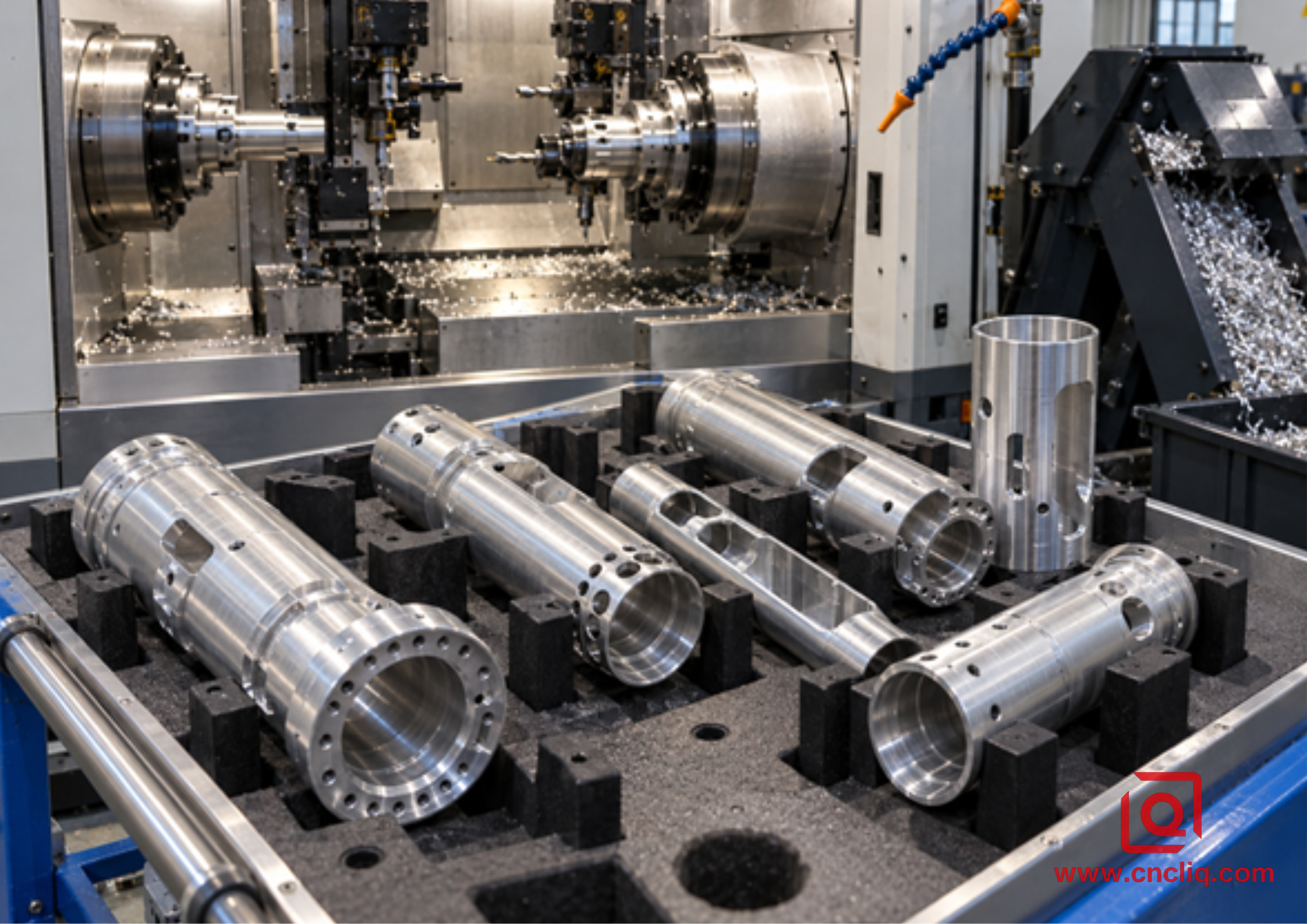
Batch of unique complex aluminum tubes beside a dual-spindle turning center
10. DFM Notes Before You Send the RFQ
Quick buyer check:
· Send the STEP model and the controlled 2D drawing together.
· Mark the bore or diameter that locates the assembly.
· Dimension clocked ports and windows from functional datums.
· Say what must happen where a drilled hole breaks into a bore.
· Give the cutter a realistic corner radius and approach path.
· Leave a sacrificial transfer land instead of forcing jaws onto a seal surface.
· State alloy, temper, stock restriction, and certificate needs.
· Define anodizing type, allowance, masking, color expectation, and post-coating sizes.
· Separate cosmetic areas and state acceptable handling marks.
· Include prototype quantity, first order, annual forecast, inspection records, packing, and destination.
A mostly rotational tube with a few side details may suit a dual-spindle C-axis or Y-axis lathe. Deep pockets and heavy 3D work may still belong on a machining center. A very small, long tube may need guide-bushing support. Our comparison of 3-axis, 5-axis, and mill-turn machining gives the wider selection logic.
11. What Liqin Needs for a Useful Quote
Start with files, material, finish, quantities, and delivery need. Then circle the three characteristics that would stop your assembly. Tell us what the tube carries, seals, locates, or rotates around. That short application note often changes the safe grip and datum plan.
Ask the quotation to name the machine family, setup count, transfer land, special jaws, critical inspection method, and exclusions. Five clear answers beat a page of spindle specifications. If the tube has a hidden burr risk or a surface the sub-spindle must not touch, say so in the first message.
Liqin can compare synchronized dual-spindle turning with Swiss machining or a conventional turn-plus-mill route. Send the drawing through our contact page for an engineering review and quotation.
FAQ
1. Is dual-spindle turning always faster than two setups?
No. Transfer removes handling and some work may overlap, but synchronization, approach, cutoff, tool sharing, and inspection still take time. Compare the full cycle and cost per accepted part. The integrated route earns its place when both ends share important datum relationships or repeat demand pays for the added setup work.
2. Can the sub-spindle grip a finished thin wall?
Yes, on a suitable part and proved setup. The grip land, contact area, pressure, material condition, speed, and following cut must work together. Released measurements at several angles are the check. A broad bored jaw or collet helps distribute load; it does not guarantee freedom from distortion.
3. How is angular clocking kept during transfer?
The control synchronizes spindle speed and orientation, and the program carries the intended phase through the handoff. The grip must then resist slip. Put the clocked holes, windows, flats, or thread start against a functional drawing datum and verify them during first-article inspection.
4. Which aluminum grade should I specify?
There is no automatic winner. 6061 is widely available and takes many finishes. 7075 offers higher strength for suitable designs but changes cost, corrosion, and finishing decisions. 2024 and 6082 serve other needs. Begin with load, environment, joining, stock form, regulation, and finish; confirm the exact temper and product form before quoting.
5. What prevents an RFQ delay?
Send a STEP model, controlled drawing, alloy and temper, quantities, forecast, finish, datums, geometric limits, threads, burr and cleanliness rules, inspection records, packaging, and destination. Flag no-touch surfaces. One sentence explaining how the tube seals or locates is often more useful than another general tolerance note.
Summary
A synchronized main-to-sub-spindle route works best when a complex aluminum tube must preserve one functional chain across its bore, ODs, side features, and back end. The shop still has to control jaw contact, released stress, heat, chips, cut order, transfer phase, and inspection. Put those items on the drawing, setup sheet, and quotation. That is how “dual spindle” becomes a repeatable process instead of a machine label.
Contact Information
Company: Ningbo Liqin Industry Co., Ltd.Daily customer maintenance & after-sales support:service@shturl. zhuwanying@cncliq.com
New inquiry, quotation & order discussion:business@shturl. zhouli@chinaliqin.com
Hotline: +86 18757148656
Disclaimer
All technical articles, material specifications, machining recommendations, and surface treatment details published on this blog are for informational and reference purposes only. Please note that general blog insights do not replace signed technical agreements. Because custom parts vary by material heat numbers, machine calibrations, and specific tolerances, binding quality specs are governed solely by your approved CAD drawings, signed contracts, and formal quality plans.
All customer case studies featured on this blog have been thoroughly anonymized and sanitized. The performance metrics, manufacturing workflows, and imagery displayed serve solely to demonstrate our custom machining capabilities and do not represent a single universal standard for all orders.
Liqin Manufacturing Team
Built on 18 years of precision engineering experience, Ningbo Liqin Industry manufactures high-tolerance metal components for demanding global markets. We operate out of a 6,500 m² production hub equipped with over 150 machines, running 4-axis and 5-axis CNC machining, mill-turn machining, cold extrusion, and pressure die casting under one roof. This setup allows us to manage projects seamlessly, taking parts from initial CAD concepts directly to finalized shipments.
We handle quality control with zero compromise. We treat tight tolerances with the engineering discipline they require. Backed by ISO 9001, ISO 13485, and IATF 16949 certifications, our QA engineers run strict IPQC, FQC, and OQC checks on every single production batch. From CMM dimensional mapping and optical profiling to hardness and salt-spray testing, we validate your critical specs upfront—so you receive drop-in ready components with zero assembly headaches or costly line stoppages. On top of manufacturing, you can rely on us for two-hour response times on new RFQs, direct support for prototype sampling, and smooth export shipping across Europe, North America, Asia, and Oceania.
Welcome your inquiries and samples. Visit our website or contact us directly for a competitive quote!
